Sail F 4 User manual

4- Stroke
Outboard Motor
F 4

Identification numbers record
Outboard motor serial number
The outboard motor serial number is stamped the port side of the clamp
bracket or the upper part of the swivel bracket.
Record your outboard motor serial number in the spaces provided to assist
you in ordering spare parts from your dealer or for refernce in case your
outboard is stolen.
1.Outboard motor serial number location
Safety information
Before mounting or operating the outboard motor, read this entire
manual.
Reading it should give you an understanding of the motor and its
operation.
Before operationg the boat, read any owner's or operator's manuals
supplied with it and all labels. Be sure you understand each item before
operating.
Do not overpower the boat with this outboard motor. Overpowering the
boat could result in loss of control. The rated power of the outboard should
be equal to or less than the rated horsepower capacity of the boat , if the
rated horsepower capacity of the boat is
unknown, consult the dealer or boat
manufacturer.
Do not modify the outboard. Modifications could make the motor unfit or
unsafe to use.
Never operate after drinking alcohol or taking drugs. About 50% of all
boating fatalities involve intoxication.
Have an approved personal flotation device (PFD) on board for every
occupant. It is a good idea to wear a PFD whenever boating. At a
minimum, children and non-swimmers should always wear PFDs, and
everyone should wear PFDs when there are potentially hazardous
boating conditions.
Gasoline is highly flammable, and its vapors are flammable and
explosive. Handle and store gasoline carefully. Make sure there are no
gas fumes or leaking fuel before starting the engine.
This product emits exhaust gases which contain carbon monoxide, a
colorless, odorless gas which may cause brain damage or death when
1
GENERAL INFORMATION
F4
1

2 3
Attach the engine stop switch lanyard to a secure place on your clothing, or
your arm or leg while operating. If you accidetally leave the helm, the lanyard
will pull from the switch, stopping the engine.
Know the marine laws and regulations where you will be boating-and obey them.
Stay informed about the weather. Check weather forecasts before boating.
Avoid boating in hazardous weather.
Tell someone where you are going: leave a Float Plan with a responsible
person. Be sure to cancel the Float Plan when you return.
Use common sense and good judgment when boating. Know your abilities,
and be sure you understand how your boat handles under the different
boating conditions you may encounter. Operate within your limits, and the
limits of your boat. Always operate at safe speeds, and keep a careful watch
for obstacles and other traffic.
Always watch carefully for swimmers during the engine operation.
Stay away from swimming areas.
When a swimmer is in the water near you shift into neutral and shut off the engine.
Important labels
Warning labels
Label
Be sure shift control is in neutral before starting engine. (except 2HP)
Do not touch or remove electrical parts when starting or during
operation.
Keep hands, hair, and other rotating parts while engine is running.
Lable
LEAKING FUEL COULD CAUSE A FIRE.
Before tilting up the engine or laying it on its side:
Turn the fuel cock to the "closed" position.
Tighten the air-vent screw on the fuel tank cap.
Caution labels
Lable
CAUTION:
Store the engine only as shown. Otherwise, engine damage could result
from Leaking oil.
Fueling instructions
GASOLINE AND ITS VAPORS ARE HIGHLY FLAMMABLE AND EXPLOSIVE!
Do not smoke when refueling, and keep away from sparks, flames, or
other sources of ignition.
Stop engine before refueling.
Refuel in a well-ventilated area. Refuel portable fuel tanks off the
boat.
Take care not to spill gasoline. If gasoline spills, wipe it up immediately with dry rags.
Do not overfillt the fuel tank.
Tighten the filler cap securely after refueling.
If you should swallow some gasoline inhale a lot of gasoline vapor, or
get gasoline in your eyes, get immediate medical attention.
If any gasoline spills onto your skin, immediately wash with soap and
water. Change clothing if gasoline spills on it.
Touch the fuel nozzle to the filler opening or funnel to help prevent electrostatic sparks.
CAUTION:
Use only new clean gasoline which has been stored in clean containers
and is not contaminated with water or foreign matter.
Gasoline
If knocking or pinging occurs, use a different brand of gasoline or premium
unleaded fuel. If unleaded gasoline is not available, then premium gasoline
can be used. If leaded gasoline is usually used, engine valves and related
parts should be inspected after every 300 hours of operation.
Recommended gasoline:
Regular unleaded gasoline
cockpit and cabin areas well ventilated. Avoid blocking exhaust outlets.
Check throttle, shift, and steering for porper operation before starting the engine.
CAUTION
Store the engine only as shown.
Otherwise, engine damage could
result from leaking oil.

4 5
Engine oil
CAUTION:
All 4-stroke engine are shipped from the factory without engine oil.
Propeller selection
The performance of your outboard motor will be critically affected by your choice
of propeller, as an incorrect choice could adversely affect performance and dould
also seriously damage the motor. Engine speed depends on the propeller size
and boat. If engine speed is too high or too low for good engine performance, this
will have an adverse effect on the engine.
Outboard motors are fitted with propellers chosen to perform well over a range of
applications, but there may be uses where a propeller with a different pitch would
be more appropriate. For a greater operating load, a smaller-pitch propeller is more
suitable as it enables the correct engine speed to be maintained. Conversely, a
larger-pitch propeller is more suitable for a smaller operating load.The dealers
stock a range of propellers, and can advise you and install a propeller on your
outboard
that is best suited to your application.
1.Propeller diameter in inches
2.Propeller pitch in inches
3.Type of propeller (propeller mark)
NOTE:
Select a propeller which will allow the engine to reach the middle or upper half
of the operating range at full throttle with the maximum boat load. If operating
conditions such as light boat loads then allow the engine r/min to rise above
the maximum recommended range, reduce the throttle setting to maintain the
engine in the proper operating range.
Main components
NOTE:
*May not be exactly as shown; also may not be included as standard equipment
on all models.
10W-30
10W-40
APISAE
SE
SF
SG
SH
SJ
-4
-20 200
32 68 104℃
40℃
Fill engine oil
Anada aceite de motor
Colocar oale de motor
Faire le plein d'huile moteur
Recommended engine oil:
4-stroke motor oil with a combination of
corresponding SAE and API as shown
in the chart
Engine oil quantity (excluding oil filter):
0.6L
1. Top cowling
2. Top cowling lock lever(s)
3. Carrying handle
4. Steering friction screw
5. Anti-cavitation
6. Propeller
7. Cooling water inlet
8. Trim handle
9. Clamp bracket
10.Tiller handle
11.Air vent screw
12.Fuel tank cap
13.Manual starter handle
14.Engine stop button/Engine
stop lanyard switch
15.Clamp screw
16.Rope attachment
17.Gear shift lever
18.Choke knob
Fuel tank
If your model included a fuel tank, its parts and functions are as follows.
17
15
16
14
13
12
3
11
18
BASIC COMPONENTS
1
2
4
5
7
8
9
10
6
7-1/2 ×8 - BS
1 2 3

6 76 7
1.Fuel tank cap
2.Air vent screw Gear shift lever
Pulling the gear shift lever towards you puts the engine in forward gear so that
the boat moves ahead.
Pulling the gear shift lever back fowards you puts
the engine in reverse gear so that the boat moves
countermarch.
Note:
Do not overtighten the friction adjuster. If there is too much resistance,
it could be difficult to move throttle lever or grip, which could result in
an accident.
When constant speed is desired, tighten the
adjuster to maintain the desired throttle
setting.
Throttle friction adjuster
A friction device provides adjustable resistance to movement of the throttle grip
or the remote control lever, and can be set according to operator preference.
To increase resistance, turn the adjuster clockwise. To decrease resistance,
turn the adjuster counterclockwise.
Throttle indicator
The fuel consumption curve on the throttle in-
dicator shows the relative amount of fuel con-
sumed for each throttle position. Choose the
setting that offers the best performance and
fuel economy for the desired operation.
1.Throttle indicator
1.Forward "F"
2.Neutral "N"
3.Reverse"R"
Throttle grip
The throttle grip is on the tillerhandle. Turn th-
e grip counterclockwise to in crease speed an-
d clockwise to decrease speed.
Fuel tank cap
This cap seals the fuel tank. When removed, the
tank can be filled with fuel. To remove the cap,
turn it counterclockwise.
Air vent serew
This screw is on the fuel tank cap. To
loosen the screw, turn it counterclockwise.
Fuel cock
The fuel cock turns on and off the supply of
fuel from the fuel tank to the engine.
1.Fuel cock
Close
To stop fuel flow to the engine or to be using
outer fuel tank, turn the lever or knob to
close position.
Always turn the lever or knob to close position
when the engine is not running.
1.Close position
Open
With the lever/knob in this position, fuel
flows to the carburetor.
Normal running is done with the lever/knob in
this position.
1.Open position
Tiller handle
To change direction, move the tiller
handle to the left or right as necessary.
12
1
F
2
N
3
R
1
1. ON
1. OFF
You should turn down the speed before you
swift the forward and reverse gear.

8 9
Engine stop lanyard switch
The lock plate must be attached to the engine stop switch for the engine to
run. The lanyard should be attached to a secure place on the operator's
clothing, or arm or leg. Should the operator fall overboard or leave the helm,
the lanyard will pull out the lock plate, stopping ignition to the engine. This
will prevent the boat from running away under power.
Attach the engine stop switch lanyard to a secure place on your clothing,
or your arm or leg while operating.
Do not attach the lanyard to clothing that could tear loose. Do not route the
lanyard where it could become entangled, preventing it from functioning.
Avoid accidentally pulling the lanyard during normal operation. Loss
of engine power means the loss of most steering control. Also,
without engine power, the boat could slow rapidly. This could cause
people and objects in the boat to be thrown forward.
NOTE:
The engine cannot be started with the lock plate removed.
1.Lock plate
2.Lanyard
Engine stop button
To open the ignition circuit and stop the engine,
push this button.
Choke knob for pull type
To supply the engine with the rich fuel mixture
required to start, pull out this knob.
Manual starter handle
To start the engine, first gently pull the handle
out until resistance is felt. From that position,
then pull the handle straight out quickly to cr-
ank the engine.
Steering friction adjuster
A friction device provides adjustable resistance to the steering mechanism,
and can be set according to operator preference. An adjusting screw or bolt is
located on the swivel braket.
To increase resistance, turn the adjuster clock-
wise.
To decrease resistance, turn the adjuster cou-
nterclockwise.
Do not overtighten the friction adjuster. If there is too much resistance,
it could be difficult to steer, which could result in an accident.
Trim rod(tilt pin)
The position of the trim rod determines the m-
inimum trim angle of the outboard motor in re-
lation to the transom.
Tilt support lever for manual tilt model
To keep the outboard motor in the tilted up
position, lock the tilt support lever to the clamp
bracket.
2
1

10 11
Top cowling lock lever (pull up type)
To remove the engine top cowling, pull up the lock lever(s) and lift off the cowling.
When installing the cowling, check to be sure it fits properly in the rubber seal.
Then lock the cowling by moving the lever(s) downward.
Carrying handle
A carrying handle is provided on the rear of the outboard motor. It enables you
to carry the outboard motor easily with one hand.
Instllation
CAUTION:
Incorrect engine height or obstructions to smooth water flow (such as the
design or condition of the boat, or accessories such as transom ladders or
depth finder transducers) can create airborne water spray while the boat is
cruising. Severe engine damage may result if the motor is operated
continuously is the presence of airborne water spray.
NOTE:
During water testing check the buoyancy of the boat, at rest, with its
maximum load. Check that the static water level on the exhaust housing is
low enough to prevent water entry into the powerhead, when water rises due
to waves when the outboard is not running.
Mounting the outboard motor
Overpowering a boat could cause severe instability. Do not install an outboard motor
with more horsepower than the maximum rating on capacity plate of the boat. If the
boat does not have a capacity plate, consult the boat manufacturer.
The information presented in this section is intended as reference only. It
is not possible to provide complete instructions for every possible boat
and motor combination. Proper mounting depends in part on experience
and the specific boat and motor combination.
Improper mounting of the outboard motor could result in hazardous conditions
such as poor handling, loss of control, or fire hazards. Observe the following:
For permanently mounted models, your dealer or other person experenced
in proper rigging should mount the motor. If your are mounting the motor
yourself, you should be trained by an experenced person.
For portable models, your dealer or other person experienced in proper
outboard motor mounting should show you how to mount your motor.
Mount the outboard on the center line (keel line) of the boat, and ensure that
the boat itself is well balanced. Otherwise the boat will be hard to steer.
Forboats without a keel or which are asymmetrical, consult your dealer.
1.Center line (keel line)
Mounting height
To run your boat at optimum efficiency, the water resistance (drag) of the boat
1
OPERATION

12 13
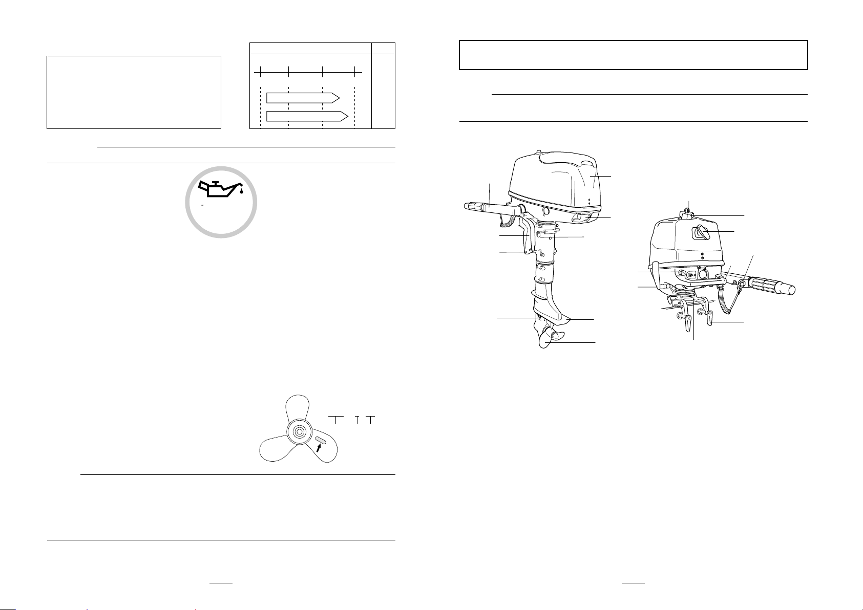
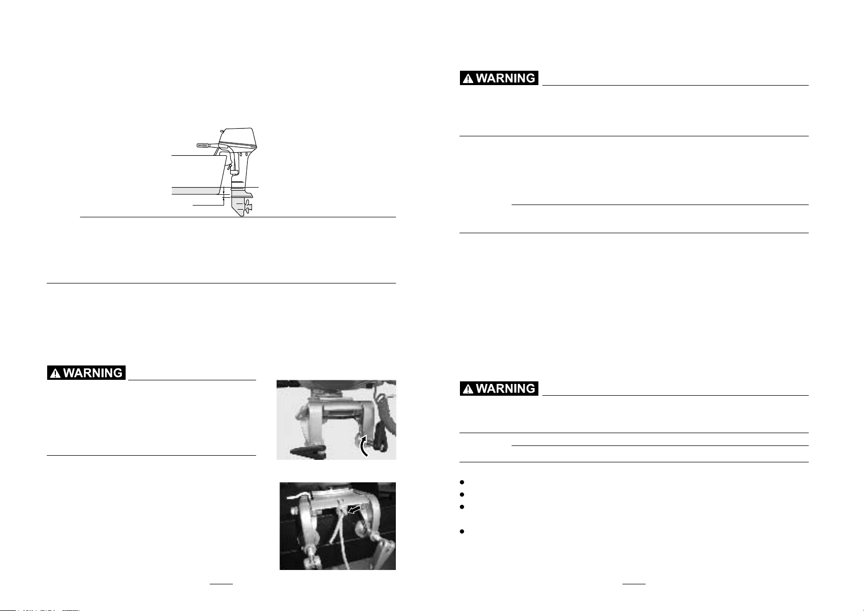
and outboard motor must be made as little as possible. The mounting height of the
outboard motor greatly affects the water resistance. If the mounting height is too hi-
gh, cavitation tends to occur, thus reducing the propulsion; and if the propeller tips
cut the air, the engine speed will rise abnormally and cause the engine to overheat.
If the mounting height is too low, the water resistance will indrease and thereby red-
uce engine efficiency. Mount the outboard motor so that the anti-cavitation plate is
between the bottom of the boat and a level 25mm (1 in.) below it.
NOTE:
The optimum mounting height of the outboard motor is affected by the boat and
motor combination and the desire use. Test runs at different heights can help d-
etermine the optimum mounting hieght. Consult your dealer or boat manufactu-
rer for further information on determining the proper mounting height.
For instructions on setting the trim angle of the outboard motor, see page 18.
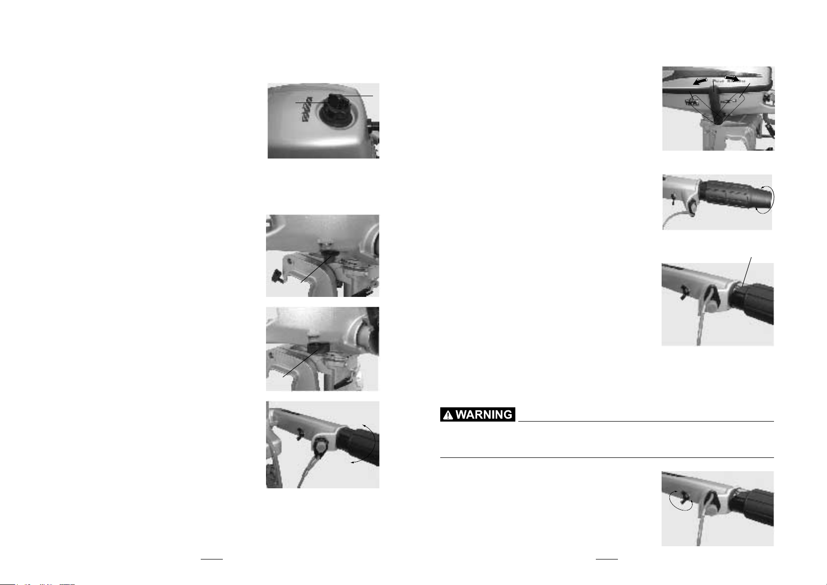
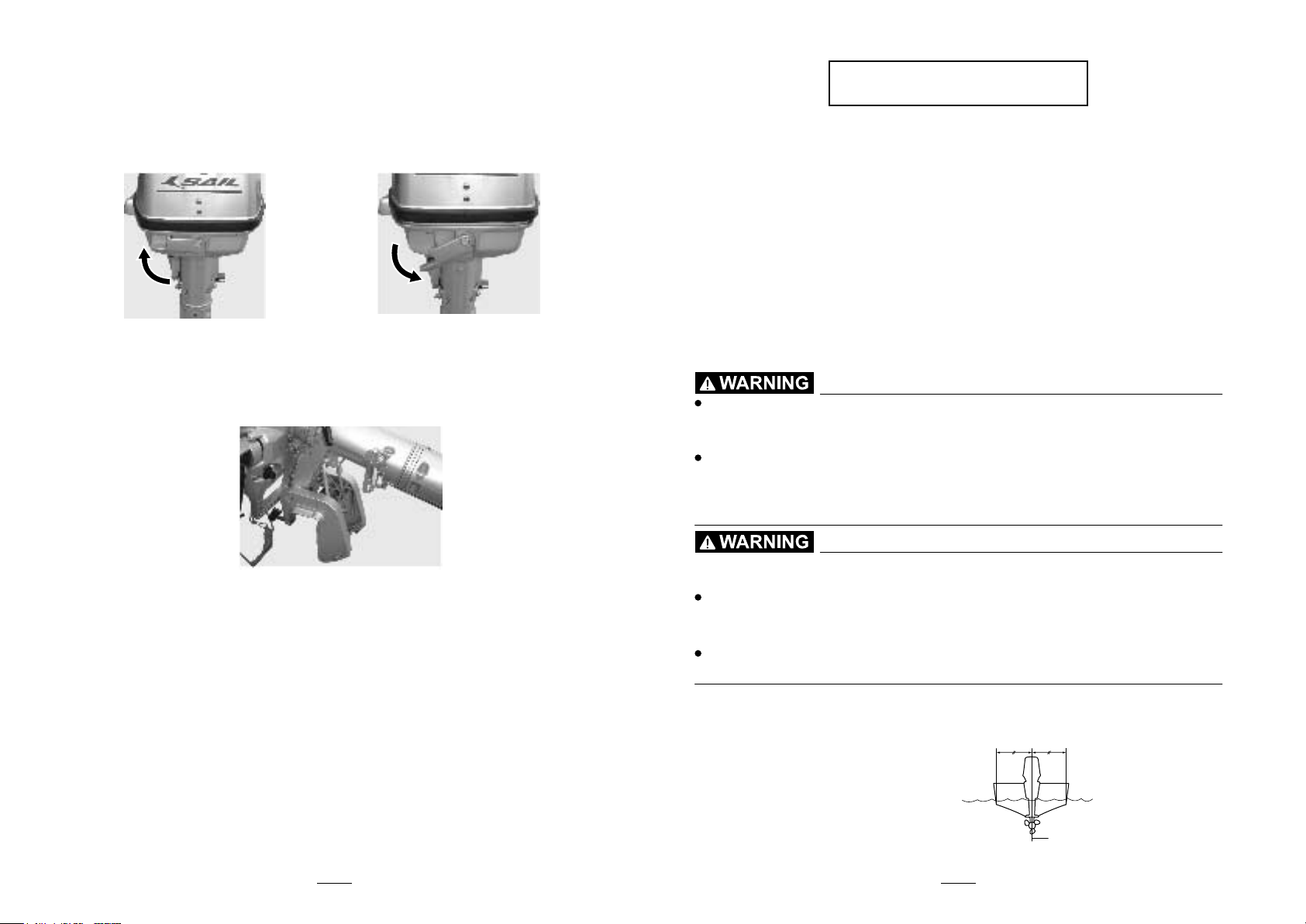
Clamping the outboard motor
1.Place the outboard motor on the transom so that it is positioned as close to
the center as possible. Tighten the transom clamp screws evenly and
securely. Occasionally check the clamp serews for tightness during
operation of the outboard motor because they could become loose due to
engine vibration.
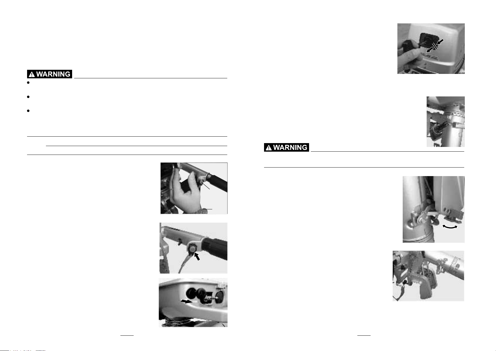
Loose clamp screws could allow the outbo-
ard motor to fall off or move on
the transom.
This could cause loss of control and serious
injury. Make sure the transom screws are tig-
htened securely. Occasionally check the scr-
ews for tightness during operation.
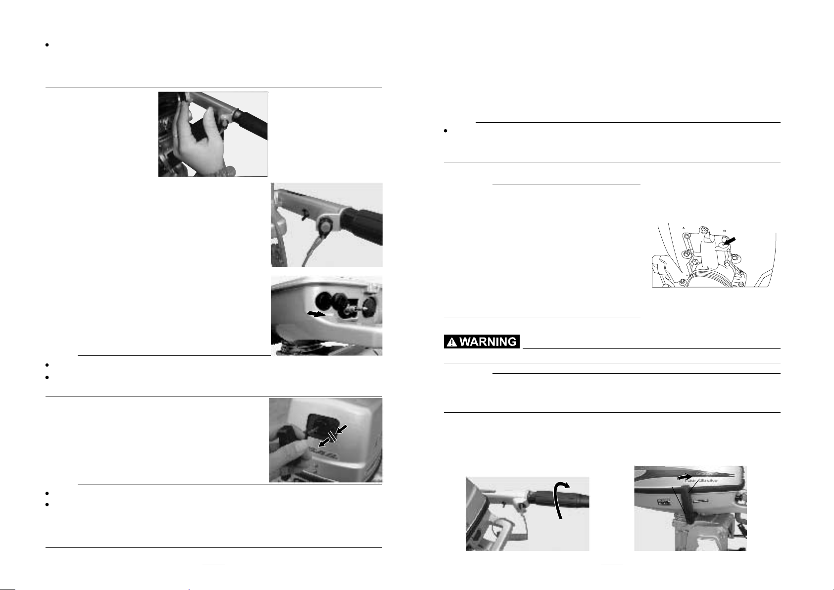
2.If the engine restraint cable attachment is
equipped on your engine, an engine restraint
cable or chain should be used. Attach one e-
nd to the engine restraint cable attachment a-
nd the other to a secure mounting point on
the boat. Otherwise the engine could be com-
pletely lost if it accidentally falls off the transom.
3.Secure the clamp bracket to the transom using the bolts provided with the
outboard (if packed). For details, consult your dealer.
Avoid using bolts, nuts or washers other than those contained in the
engine packaging. If used, they must be of at least the same quality of
material and strength and must be tightened securely. After tightening,
test run the engine and check their tightness.
Breaking in engine
Your new engine requires a period of break-in to allow mating surfaces of
moving parts to wear in evenly. Correct break-in will help ensure proper
performance and longer engine life.
CAUTION:
Failure to follow the break-in procedure could result in reduced engine
life or even severe engine damage.
Procedure for 4-stroke models
Run the engine under load (in gear with a propeller installed) as follows.
1.For the first hour of operation:
Run the engine at 2000 r/min or at approximately half throttle.
2.For the second hour of operation:
Run the engine at 3000 r/min or at approximately three-quarter throttle.
3.For the next eight hours of operation:
Avoid continuous operation at full throttle for more than five minutes at a time.
4.After the first 10 hours:
Operate the engine normally.
Preoperation checks
If any item in preoperation check is not working properly, have it inspected
and repaired before operationg the outboard motor. Otherwise an accident
could occur.
CAUTION:
Do not start the engine out of water. Overheating and serious engine damage can occur.
Fuel
Check to be sure you have plenty of fuel for your trip.
Make sure there are no fuel leaks or gasoline fumes.
Check fuel line connections to be sure they are tight (if equipped fuel tank
or boat tank).
Be sure the fuel tank is positioned on a secure, flat surface, and that the f-
uel lines is not twisted of flattened, or likely to contact sharp objects (if eq-
uipped fuel tank or boat tank).
0-25mm
(0-in.)

14 15
Controls
Check throttle, shift, and steering for proper operation before starting the engine.
The controls should work smoothly, without binding or unusual free play.
Look for loose or damaged connections.
Check operation of the starter and stop switches when the outboard motor is in the water.
Engine
Check the engine and engine mounting.
Look for loose or damaged fasteners.
Check the propeller for damage.
Checking the engine oil level
1.Put the outboard motor in an upright position (not tilted).
2.Pull out the oil dipstick and wipe it cleam.
3.Completely resinsert the dipstick and pullout it again.
4.Check the oil lever using the dipstick to be sure the lever falls between the
wpper and lower marks.Fill with oil if it is below the lower mark, or drain to the
specificl level if it is above the upper mark.
3.Upper level mark
1.Oil dipstick 2.Lower level mark
Gasoline and its vapors are highly flammable and explosive. Keep awa-
y from sparks, cigarettes, flames, or other sources of ignition.
1.Remove the fuel tank cap.
2.Carefully fill the fuel tank.
3.Securely close the cap after filling the tank. Wipe up any spilled fuel.
Before starting the engine, make sure that the boat is tightly moored
and that you can steer clear of any obstructions. Be sure there are no
swimmers in the water near you.
Operating engine
Feeding fuel
Filling fuel
When the air vent screw is loosened, gasoline vapor will be released.
Gasoline is highly flammable, and its vapors are flammable and expl-
osive. Refrain from smoking, and keep away from open flames and
sparks while loosening the air vent screw.
This product emits exhaust gases which contain carbon monoxide, a
colorless, odorless gas which could cause brain damage or death w-
hen inhaled. Symptoms include nausea, dizziness, and drowsiness.
Keep cockpit and cabin areas well ventilated. Avoid blocking exhaust
outlets.
1.For the built in tank, loosen the air vent screw on the fuel tank cap by one
turn. For the external fuel tank, loosen it on the fuel tank cap by 2 or 3 turns.
2.Select the fuel tank using the fuel cock or open the fuel cock.
3.Squeeze the primer pump with the outlet end up until you feel it become firm
(if equipped the fuel joint).
Starting engine
Manual start models
1.Place the gear shift lever in neutral
Always start the engine in neutral to avoid accidentally moving the boat.
2.If the engine stop switch lanyard is equipp-
ed, attach it to a secure place on your clothi-
ng, or your arm or leg. Then install the lock
plate on the other and of the lanyard into the
engine stop switch.
Attach the engine stop switch lanyard to a secure place on your clot-
hing, or your arm or leg while operating.
Do not attach the lanyard to clothing that could tear loose. Do not route
the lanyard where it could become entangled, preventing it from
functioning.
Fuel tank capacity:
1.3 L (0.344 US gal)(0.286 Imp.gal)
N
2
3
1

16 17
Avoid accidentally pulling the lanyard during normal operation. Loss
of engine power means the loss of most steering control. Also, with-
out engine power, the boat could slow rapidly. This could cause peo-
ple and objects in the boat to be thrown forward.
3.Place the throttle grip in the "START" (start)
position.
4.Place the choke knob in the "START" (start)
position. After the engine starts, return the kn-
ob to the "RUN" (run) position.
NOTE:
When restarting a warm engine, place the choke knob in the "RUN" (run) position.
If the choke knob is left in the "START" (start) position while the engine is
running, the engine will run poorly or stall.
5.Pull the manual starter handle slowly until
you feel resistance. Then give a strong pull
straight out to start the engine. Repeat if necessary.
6.After the engine starts, slowly return the m-
anual starter handle to the original position before releasing it.
7.Slowly return the throttle grip to the fully closed position.
NOTE:
When the engine is cold, it needs to be warmed up.
If the engine does not start on the first try, repeat the procedure. If the engine
fails to start after 4 or 5 tries, open the throttle a small amount (between 1/8
and 1/4) and try again. Also if the engine is warm and fails to start, open the
throttle a same amout and try to start the engine again.
Warming up engine
Manual start models
1. After starting the engine, return the choke knob to the halfway position.
For approximately the first 5 minutes after starting, warm up the engine by
operating at one fifth throttle or less. After the engine has warmed up, push
the choke knob in fully. Failure to do so will shorten engine life.
NOTE:
If the choke knob is left pulled out after the engine starts, the engine will stall.
In temperatures of -5℃or less, leave the choke knob pulled out fully for app-
roximately 30 seconds after starting.
2. Check for a steady flow of water from the cooling water pilot hole.
CAUTION:
A flow of water from the hole on the exha-
ust cover shows that the water pump is p-
umping water through the cooling passa-
ges. If water is not flowing out of the hole
at all times while the engine is running,
overheating and serious damage could
occur. Stop the engine and check whether
the cooling water inlet on the lower case
or the cooling water pilot hole is blocked.
Consult your dealer if the problem cannot
be located and corrected.
Shifting
Before shifting, make sure there are no swimmers or obstacles in the water near you.
CAUTION:
To change the boat direction or shifting position from forward to rever-
se or viceversa, first close the throttle so that the engine idles (or runs
at low speeds.)
Forward (tilller handle and remote control models)
Tiller control models
1. Place the throttle grip in the fully closed position.
2. Move the gear shift lever quickly and firmly from neutral to forward.
NF

18 19
Remote control models
Pull up the neutral interlock trigger (if equipped) and move the remote
control
lever quickly and firmly from neutral to forward.
Reverse
When operating in reverse, go slowly. Do not open the throttle more th-
an half. Otherwise the boat could become unstable, which could result
in loss of control and an accident.
1. Place the throttle grip in the fully closed position.
2. Move the gear shift lever quickly and firmly from neutral to reverse.
NOTE:
Stopping engine
Before stopping the engine, first let it cool off for a few minutes at idle or low
speed. Stopping the engine immediately after operating at high speed is not
recomended.
Procedure
1.
Push and hold the engine stop button until the
engine comes to a complete stop.
2. After stopping the engine, tighten the air v-
ent screw on the fuel tank cap and set the fu-
el cock lever or knob to the closed position, if equipped.
3. Disconnect the fuel line if you are using an
external fuel tank.
NOTE:
If the outboard motor is equipped with an engine stop switch lanyard, the
engine can also be stopped by pulling the lanyard and removing the lock
plate from the engine stop switch.
Trimming outboard motor
The trim angle of the outboard motor helps determine the position of the blo-
w of the boat in the water. Correct trim angle will help improve performance
and fuel economy while reducing strain on the engine. Correct trim angle depends
upon the combination of boat, engine, and propeller. Correct trim is also affected by
variables such as the load in the boat, sea conditions, and running speed.
Excessive trim for the operating conditions (either trim up or trim down)
can cause boat instability and can make steering the boat more difficult.
This increases the possibility of an accident. If the boat begins to feel u-
nstable or is hard to steer, slow down and/or readjust the trim angle.
1. The trim angle adjusting rod
Stop the engine before adjusting the trim angle.
Use care to avoid being pinched when removing or installing the rod.
Use caution when trying a trim position for the first time. Increase sp-
eed gradually and watch for any signs of instability or control proble-
ms. Improper trim angle can cause loss of control.
NOTE:
The outboard motor trim angle can be changed approximately 4 degrees by
shifting the trim rod one hole.
1
N
R
ADJUSTING TRIM ANGLE
Manual tilt model
There are 4 or 5 holes provided in the clamp bracket to adjust the outboard
motor trim angle.
1) Stop the engine.
2)
Remove the trim angle adjusting rod ①from the clamp bracket while tilting the motor
up slightly.
3) Reposition the rod in the desired hole.
To raise the bow ("trim-out"), move the rod away from the transom.
To lower the bow ("trim-in"), move the rod toward the transom.
Make test runs with the trim set to different angles to find the position that works best for
your boat and operating conditions.
1

20 21
Adjusting boat trim
When the boat is on plane, a bow-up attitude results in less drag, greater
stability and efficiency. This is generally when the keel line of the boat is up
about 3 to 5 degres. With the bow up, the boat may have a greater tende-
ncy to steer to one side or the other. Compensate for this as you steer. The
trim tab can also be adjusted to help offset this effect. When the bow of the
boat is down, it is easier to accelerate from a standing start onto plane.
Bow Up
Too much trim-out puts the bow of the boat too high in the water. Performan-
ce and economy are decreased because the hull of the boat is pushing the
water and there is more air drag. Excessive trim-out can also cause the pr-
opeller to ventilate, which reduces performance further, and the boat may
"porpoise" (hop in the water), which could throw the operator and passenge-
rs overboard.
Bow Down
Too much trim-in causes the boat to "plow" through the water, decreasing
fuel
economy and making it hard to increase speed. Operating with excessive
trim-
in at higher speeds also makes the boat unstable. Resistance at the bow is
greatly increased, heightening the danger of "bow steering" and making
operation difficult and dangerous.
NOTE:
Depending on the type of boat, the outboard motor trim angle may have little
effect on the trim of the boat when operating.
Tilting up and down
If the engine will be stopped for some time or if the boat is moored in
shallows,
the outboard motor should be tilted up to protect the propeller and casing fr-
om damage by collision with obstructions, and also to reduce salt corrosion.
Be sure all people are clear of the outboard motor when tilting up and
down, also be careful not to pinch any body parts between the drive u-
nit and engine bracket.
Leaking fuel is a fire hazard. Tighten the air vent screw and place the fuel
cock in the closed position if the outboard motor will be tilted for more
than a few minutes. Otherwise fuel may leak.
CAUTION:
Before tilting the outboard motor, follow the procedure under
"Stopping
engine" in this chapter. Never tilt the outboard motor while the engine
is running. Sever damage from overheating can result.
Do not tilt up the engine by pushing the tiller handle because this could
break the handle.
Keep the power unilt higher than the propeller at all times. Otherwise water
could run into the cylinder and cause damage.
The outboard motor cannot be tilted when in reverse or when the outboard
motor is turned 180℃ (facing the rear).
Procedure for tilting up (manual tilt models)
1. Place the gear shift lever in neutral (if equipped) and face the outboard motor forward.
2. On full-pivot system models, tighten the steering friction adjuster by turning
it clockwise to prevent the motor from turning freely.
3. Tighten the air vent screw. On models equipped with a fuel joint, disconnect
the fuel line from the outboard motor.
4. Close the fuel cock.

22
5. Tilt support bar equipped models: Hold the rear of the top cowling or the
rear rhandle (if equipped) with one hand and tilt the outboard motor up fully
un-til the tilt support bar automatically locks.
6. Tilt support knob equipped models: Hold the rear of the top cowling with
one hand, fully tilt the outboard motor up, and push the tilt support knob into
the clamp bracket.
7. Tilt support lever equipped models: Hold the rear handle and tilt engine up
fully until the tilt support lever automatically locks.
NOTE:
Tilt support lever/bar equipped models: If the motor is not facing forward, the
tilt support lever/bar cannot automatically turn to the locked position. If the tilt
support lever/bar does not automatically lock, swing the motor a little to the
left and right.
Procedure for tilting down (manual tilt models)
1. Slightly tilt the outboard motor up.
2. If the tilt support bar equipped: Slowly tilt the outboard motor down while
pulling the tilt support bar lever up.
3. If the tilt support knob equipped: pull out it, then slowly tilt the engine down.
4. Loosen the steering friction adjuster by turning it counterclockwise, and a-
djust the steering friction according to operator preference.
If there is too much resistance it could be difficult to steer, which could
result in an accident.
Unit
model F4-L F4-S
item
Dimension
OveralI lenth 680 680
400 400
23.8 23.8
1200 1080
OveraII Width
OveraII height
Weight(AL)S
Performance
Full throttle 0perating range 5250~5750
Maximum Output kW(HP)@r/min 3(4)@5500
Idle speed(in neutral) r/min
r/min
1600±100
Engine
Type 4一scroke S
Displacement cm3 112
mm
Bore×stroke 59x41
Ignition System TCl
(NGK)
Spark plug BPR7HS
mm
Spark plug gap 0.6-0.7
CORlrol syscem Tiller
Starting carburetion system Choke valve
Valve clearance(COld engine) lN 0.08-0.12
0.08-0.12
Valve clearance(COld engine) EX
Drive unit
Gear positions Forward-neutral-reverse
Gear ratio 2.08(27/13)
Trim and tilt system Manual tilt
Propeller mark BS
Fuel and oil
Recomended fuel Unleaded regular gasoline
Fuel tank capacity (inner/outer) 1.3/18
Recommended engine oil 4-stroke outboard motor oil
Engine oil grade APl SE,SF,SG,SH,SJ
Engine oil type SAE 10W30 or 10W40
Lubrication Wet sump
Engine oil quantity(excluding oil filter) L
L
0.60~0.65
Gear oil quantity cm3 120
Tightening torque for engine
Spark plug
Engine oil drain bolt
25.0
N.m
N.m18.0
mm
mm
mm
mm
mm
kg
Specifications
23

24 25
Be sure to turn off the engine when you perform maintenance unless othe-
rwise specified. If you or owner is not familiar with machine servicing, this
work should be done by your "SAIL" dealer or other qualified mechanic.
Replacement parts
If replacement parts are necessary, use only genuine parts or parts of the s-
ame type and of equivalent strength and materials. Any part of inferior qual-
ity may malfunction, and the resulting loss of control could endanger the op-
erator and passengers."SAIL" genuine parts and accessories are available
from your dealer.
Maintenance chart
Frequency of maintenance operations may be adjusted according to the op-
erating conditions, but the following table gives general guidelines. Refer to
the sections in this chapter for explanations of each owner-specific action.
The "
" symbol indicates the check-ups which you may carry out yourself.
The "
" symbol indicates work to be carried out by your "SAIL" dealer.
NOTE:
When operating in salt water, turbid or muddy water, the engine should be
flushed with clean water after each use.
Item
Anode(s) (external) Inspection/
replacement
Inspection/
replacement
Anode(s) (internal)
Cowling clamp Inspection/cleaning
Fuel system Inspection
Fuel tank (built-in tank)
Inspection / cleaning
Inspection /
replacement
Gear oil
Greasing points
Propeller and cotter pin
Shift link / shift cable
Thermostat
Water pump
Engine oil
Spark plug(s)
Valve clearance
(OHC, OHV)
Throttle link / throttle
cable / throttle pick-up
timing
Idling speed
(carburetor models)
Change
Greasing
Inspection / adjustment
Inspection
Inspection
Inspection / change
Cleaning / adjustment /
replacement
Fuel filter (inside built-
in fuel tank) Inspection / cleaning
Cooling water
passages Cleaning
Actions
Initial
10 hours
(1 month)
50 hours
(3 months)
100 hours
(6 months)
200 hours
(1 year)
Every
Cleaning / adjustment
PERIODIC MAINTENANCE

26 27
Cleaning and adjusting spark plug
When removing or installing a spark plug, be careful not to damaged insul-
ator could allow external sparks, which could lead to explosion or fire.
The spark plug is an important engine component and is easy to inspect. The
condition of the spark plug can indicate something about the condition of the
engine. For example, if the center electrode porclain is very white, this could
indicate an intake air leak or carburetion problem in that cylinder. Do not atte-
mpt to diagnose any problems yourself. Instead, take the outboard motor to a
dealer. You should periodically remove and inspect the spark plug becausee
heat and deposits will cause the spark plug to slowly break down and erode.
If electrode erosion becomes excessive, or if carbon and other deposits are
excessive, you should replace the spark plug with another of the correct type.
Greasing
Grease A (water resistant grease)
Grease D (corrosion resistant grease; for propeller shaft)
tandard spark plug:
BPR7HS
Before fitting the spark plug, measure the electrode gap with a wire thickness
gauge; adjust the gap to specification if necessary.
1. Spark plug gap
2. Spark plug I.D.mark (NGK)
Spark plug gap:
0.6-0.7 mm(0.024-0.028 in)
When fitting the plug, alaways clean the gasket surface and use a new gasket. Wipe
off any dirt from the threads and screw in the spark plug to the correct torque.
Spark plug torque:
25.0 Nm(18.4 ft-ib)(2.55 kgf-m)
NOTE:
If a torque-wrench is not available when you are fitting a spark plug, a good
estimate of the correct torque is 1/4 to 1/2 a turn past fingertight. Have the
spark plug adjusted to the correct torque as soon as possible with a torquewrench.
Checking fuel system
Gasoline and its vapors are highly flammable and explosive. Keep away
from sparks, cigarettes, flames, or other sources of ignition.
Leaking fuel can result in fire or explosion.
Check for fuel leakage regularly.
If any fuel leakage is found, the fuel system must be repaired by a qualified
michanic. Improper repairs can make the outboard unsafe to operate.
Check the fuel lines for leaks, crack, or malfunction. If a problem is found, your
dealer or other qualified mechanic should repair it immediately.
Checkpoints
Fuel system parts leakage
Fuel line joint leakage
Fuel line cracks or other damage
Fuel connector leakage
12

28 29
Inspecting idling speed
Do not touch or remove electrical parts when starting or during operation.
Keep hands, hair, and clothes away from the flywheel and other rotat-
ing parts while the engine is running.
2-hp models: The propeller rotates whenever the engine is running. Do not
move the throttle control lever from the start position during warm-up. The
boat could unexpectedly start to move, which could result in an accident.
CAUTION:
This procedure must be performed while the outboard motor is in the water.
A flushing attachment or test tank can be used.
A diagnostic tachometer should be used for this procedure. Results may vary
depending on whether testing is conducted with the flushing attachment, in a
test tank, or with the outboard motor in the water.
1. Start the engine and allow it to warm up fully in neutral until it is running s-
moothly. 2-hp model: Warm the engine with the throttle in the start position
or less. If the outboard is mounted on a boat is tightly moored.
NOTE:
Correct idling speed inspection is only possible if the engine is fully warmed
up. If not warmed up fully, the idle speed will measure higher than normal. If
you have difficulty verifying the idle speed, or the idle speed requires adjustment,
consult a dealer or other qualified mechanic.
2. Verify whether the idle speed is set to specification. For idle speed specifications, see page 23.
Changing engine oil
Avoid draining the engine oil immediately after stopping the engine.
The oil is hot and should be handled with care to avoid burns.
Be sure the outboard motor is securely fastened to the transom or a stable stand.
CAUTION:
Do not overfill the oil, and be sure the outboard motor is upright (not
tilted) when checking and changing the engine oil.
If the oil level is above the upper level mark, drain until the level meets the
specified capacity. Overfilling the oil could cause leakage or damage.
1. Put the outboard motor in an upright
position (not tilted).
2. Prepare a suitable container that holds a larger amount than the engine oil
capacity. Loosen and remove the drain screw while holding the container un-
der the drain hole. Then remove the oil filler cap. Let the oil drain completely.
Wipe up any spilled oil immediately.
3. Put a new gasket on the oil drain screw. Apply a light coat of oil to the gas-
ket and install the drain screw.
Drain screw tightening torque:
18.0 Nm (13.3 ft-ib)(1.84 kgf-m)
NOTE:
If a torque wrench is not available when you are installing the drain screw, fi-
nger tighten the screw just until the gasket comes into contact with the surfa-
ce of the drain hole. Then tighten 1/4 to 1/2 turn more. Tighten the drain scr-
ew to the correct torque with a torque wrench as soon as possible.
4. Add the correct amount of oil through the filler hole. Install the filler cap.
Recommended engine oil:
4-stroke outboard motor oil
Engine oil quantity (excluding oil filter):
0.4 L(0.42 US qt)(0.35 Imp.qt)
5. Start the engine and watch to make sure the low oil pressure warning indicator
(if equipped) turns off. Make sure that there are no oil leaks.
CAUTION:
If the low oil pressure warning indicator does not turn off or if there are
oil leaks, stop the engine and find the cause. Continued operation with
a problem could cause severe engine damage. Consult your dealer if
the problem cannot be located and corrected.
6. Turn off the engine and wait 3 minute. Pull out the oil dipstick and wipe it
cleam.Completely resinsert the dipstick and pullout it again.Check the oil
level using the dipstick to be sure the level falls between the upper and lower
marks,Fill with oil if it is below the lower mark,or drain to the specific level if it
is above the upper mark.
7 . Dispose of used oil according to local regulations .

30 31
NOTE:
For more information on the disposal of used oil, consult your dealer.
Change the oil more often when operating the engine under adverse cond-
itions such as extended trolling.
Checking wiring and connectors
Check that each grounding wire is properly secured.
Check that each connector is engaged securely.
Exhaust leakage
Start the engine and check that no exhaust leaks from the joints between the
exhaust cover, cylinder head, and body cylinder.
Water leakage
Start the engine and check that so water leaks from the joints between the
exhaust cover, cylinder head, and body cylinder.
Engine oil leakage
Check for oil leads on the around the engine.
NOTE:
If any leaks are found, consult your dealer.
Checking propeller
You could be seriously injured if the engine accidentally starts when you
are near the propeller.
Before inspecting, removing, or installing the propeller, remove the spark
plug caps from the spark plugs. Also, place the shift control in neutral, t-
urn the main switch to "OFF" (off) and remove the key, and remove the l-
anyard from the engine stop switch. Turn off the battery cut-off switch if
your boat has one.
Do not use your hand to hold the propeller when loosening or tightening
the propeller nut. Put a wood block between the anti-cavitation plate and
the propeller to prevent the propeller from turning.
Checkpoints
Check each of the propeller blades for wear, erosion from cavitation or ve-
ntilation, or other damage.
Check the propeller shaft for damage.
Check the splines / shear pin for wear or damage.
Check for fish line tangled around the propeller shaft.
Check the propeller shaft oil seal for damage.
NOTE:
If the shear pin equipped: it is designed to break if the propeller hits a hard underwat-
er obstacle to help protect the propeller and drive mechanism. The propeller will then
spin freely on the shaft. If this happens, the shear pin must be replaced.
Removing the propeller
1. Straighten the cotter pin and pull it out using a pair of pliers.
2. Remove the propeller nut, washer, and sapcer (if equipped).
1. Cotter pin
2. Propeller nut
3. Washer
4. Propeller
5. Thrust washer
3. Remove the propeller and thrust washer.
Installing the propeller
CAUTION:
Be sure to install the thrust washer before installing the propeller, oth-
erwise the lower case and propeller boss could be damaged.
Be sure to use a new cotter pin and bend the ends over securely. Oth-
erwise the propeller could come off during operation and be lost.
1. Apply marine grease or a corrosion resistant grease to the propeller shaft.
2. Install the spacer (if equipped), thrust washer, and propeller on the propeller shaft.
3. Install the spacer (if equipped) and the washer. Tighten the propeller nut until
there is no forward-backward movement.
4. Align the propeller nut with the propeller shaft hole. Insert a new cotter pin
in the hole and bend the cotter pin ends.
NOTE:
If the propeller nut does not align with the propeller shaft hole after tightening
it, loosen the nut until it aligns with the hole.
1
2
3
4
5

33
Changing gear oil
Be sure the outboard motor is securely fastened to the transom or a stable
stand. You could be severely injured if the outboard motor falls on you.
Never get under the lower unit while it is tilted, even when the tilt su-
pport lever or knob is locked. Severe injury could occur if the outbo-
ard motor accidentally falls.
1. Tilt the outboard motor so that the gear oil drain screw is at the lowest point possible.
2. Place a suitable container under the gear case.
3. Remove the gear oil drain screw.
1. Gear oil drain screw
2. Oil level plug
NOTE:
If the magnetic gear oil drain screw equipped: remove all metal particles
from the screw before installing it.
4. Remove the oil level plug to allow the oil to drain completely.
CAUTION:
Inspect the used oil after it has been drained. If the oil is millky, water is
getting into the gear case which can cause gear damage. Consult a dealer
for repair of the lower unit seals.
NOTE:
For disposal of used oil consult your dealer.
5. With the outboard motor in a vertical position, and using a flexible or pres-
surized filling device, inject the gear oil into the gear oil drain screw hole.
Recommended gear oil:
Hypoid gear oil SAE#90
Gear oil quantity:
120 cm3 (4.064 US oz)(4.24 Imp.oz)
6. When the oil begins to flow out of the oil level plug hole, insert and tighten
the oil level plug.
7. Insert and tighten the gear oil drain screw.
Inspecting and replacing anode(s)
Outboard motors are protected from corrosion by sacreficial anodes. Inspect
the external anodes periodically. Remove scales from the surfaces of the
anodes. Consult a dealer for replacement of external anodes.
2
1
32
CAUTION:
Do not paint anodes, as this would render them ineffective.
NOTE:
Inspect ground leads attached to external anodes on equipped models. Con-
sult a dealer for inspection and replacement of internal anodes attached to t-
he power unit.
Checking top cowling
Check the fitting of the top cowling by pushing it with both hands. If it is loose
have it repaired by your dealer.
Coating the boat bottom
A clean hull improves boat performance. The boat bottom should be kept as
clean of marine growth as possible. If necessary, the boat bottom can be co-
ated with an antifouling paint approved for your area to inhibit marine growth.
Do not use anti-fouling which includes copper or graphite. These paints can
cause more repid engine corrosion.
Table of contents
Other Sail Outboard Motor manuals
Popular Outboard Motor manuals by other brands

MINN KOTA
MINN KOTA RIPTIDE TERROVA CP-80 installation instructions

Watersnake
Watersnake GEO-SPOT GPS SW65/54 owner's manual

Yamaha
Yamaha 40B owner's manual

Old Town Canoe Co.
Old Town Canoe Co. Predator XL Owner's manual supplement

Suzuki Marine
Suzuki Marine DF40A owner's manual

Torqeedo
Torqeedo BaseTravel 401 S operating manual

Sleipner
Sleipner ERV250/300TC-48V installation guide

Evinrude
Evinrude E-TEC 40RL 2008 Operator's guide

SLEIPNER MOTOR AS
SLEIPNER MOTOR AS SE 30 S IP Installation and user manual

BRP
BRP 2995 Johnson Service manual

TOHATSU
TOHATSU M 6B owner's manual

SLEIPNER MOTOR AS
SLEIPNER MOTOR AS SIDE-POWER SEP Series Installation and user manual