SAINT-GOBAIN ABRASIVES CG 252 User manual

CG 252
OPERATING INSTRUCTIONS
Translation of the original instructions

VERS. 2017.06.01. CG 252_MAN_EN
2

VERS. 2017.06.01. CG 252_MAN_EN
3
The undersigned manufacturer:
SAINT - GOBAIN ABRASIVES S.A.
190, BD. J. F. KENNEDY
L-4930 BASCHARAGE
Declares that this product:
Grinding machine : CG 252 Code : 70184694290
is in conformity with the following Directives:
"MACHINES" 2006/42/CE
"BASSE TENSION" 2006/95/ CE
" ELECTROMAGNETIC COMPATIBILITY" 2004/108/CE
"NOISE" 2000/14/CE
Valid for machines as of serial number:
1411000000
Storage site for the technical documents :
Saint-Gobain Abrasives 190, Bd. J. F. Kennedy 4930 BASCHARAGE, LUXEMBOURG
This declaration of conformity loses its validity when the product is converted or modified
without agreement.
Bascharage, Luxembourg, 01.11.2014.
Olivier Plenert, executive officer.
Declaration of conformity

VERS. 2017.06.01. CG 252_MAN_EN
4
CG 252 : OPERATING INSTRUCTIONS
TABLE OF CONTENTS
1BASIC SAFETY INSTRUCTIONS 5
1.1 Symbols 5
1.2 Machine plate 5
1.3 Safety instructions for particular operating phases 6
2MACHINE DESCRIPTION 7
2.1 Short description 7
2.2 Purpose of use 7
2.3 Technical Data 9
2.4 Statement regarding the vibration emission 10
2.5 Statement regarding noise emission 11
3ASSEMBLY AND COMMISSIONING 12
3.1 Tool assembly 12
3.2 Establishment of connections 12
3.3 Establishment of the dust extractors. 12
3.4 Establishment of the water supply 12
3.5 Starting the machine 12
4TRANSPORT AND STORAGE OF THE MACHINE 14
4.1 Security for transport 14
4.2 Transport procedure 14
4.3 Storage of machine 14
5OPERATING THE MACHINE 15
5.1 Site of work 15
5.2 Specific Adjustment of the machine 15
5.3 Polishing and preparation of the ground with the CG 252 18
6MAINTENANCE AND SERVICING 19
7FAULTS : CAUSES AND CURES 20
7.1 Fault-finding procedures 20
7.2 Trouble-shooting guide 20
7.3 Circuit diagram 20
7.4 Customer service 21

VERS. 2017.06.01. CG 252_MAN_EN
5
1 BASIC SAFETY INSTRUCTIONS
The CG 252 is exclusively destined for the polishing and the preparation of the ground with
NORTON polishing and surfacing tools, mainly on construction sites.
Uses other than the manufacturer's instructions shall be considered as contravening the
regulations. The manufacturer shall not be held responsible for any resulting damage. Any
risk shall be borne entirely by the user. Observing the operating instructions and compliance
with inspection and servicing requirements shall also be considered as included under use in
accordance with the regulations.
1.1 Symbols
The advice and warnings are represented by pictograms on the machine. You will find the
following symbols on the machines NORTON. Here is their explanation:
The meanings of these symbols are:
Hearing Protection mandatory
Safety glasses with side protection mandatory
CE marking of the machine
Safety Shoes mandatory
Read the Handbook is mandatory before using the machine
1.2 Machine plate
Important data can be found on the following plate located on the machine :
Machine Model
Machine Code
Weight
Year of production
Maximun tool Diameter
Do not apply
For the
CG 252
Machine Typ
Serial number
Power
Do not apply
For the
CG 252
Tool rotation speed

VERS. 2017.06.01. CG 252_MAN_EN
6
1.3 Safety instructions for particular operating phases
Before commencing work
Read the present operator’s instructions booklet carefully.
Familiarize yourself with the environment at the place of intervention. This work
environment includes, for example, the difficulties of execution, the obstacles to the
movement, respect for floor loads, security marking necessary delimiting the construction
site by report to the public traffic and the possibility of intervention of emergency in case of
accident.
Regularly check if the disks of polishing or surfacing are fixed correctly.
Unmount immediately the tools of polishing or surfacing deformed or damaged, because
they pose a risk of accident during the rotation.
Regularly check the flexible coupling because its life is directly related to the conditions
of use of the machine.
Only use the machine with its protective casings and its covers for the electrical box
fixed.
Verify that the protective casing slides vertically and freely.
When using the machine the protective casing must always be in contact with the ground.
For a dry use only use the machine with a dust extractors. (A nozzle is provided for this
purpose)
Check that all hoses (suction and water supply) are not damaged and properly
connected.
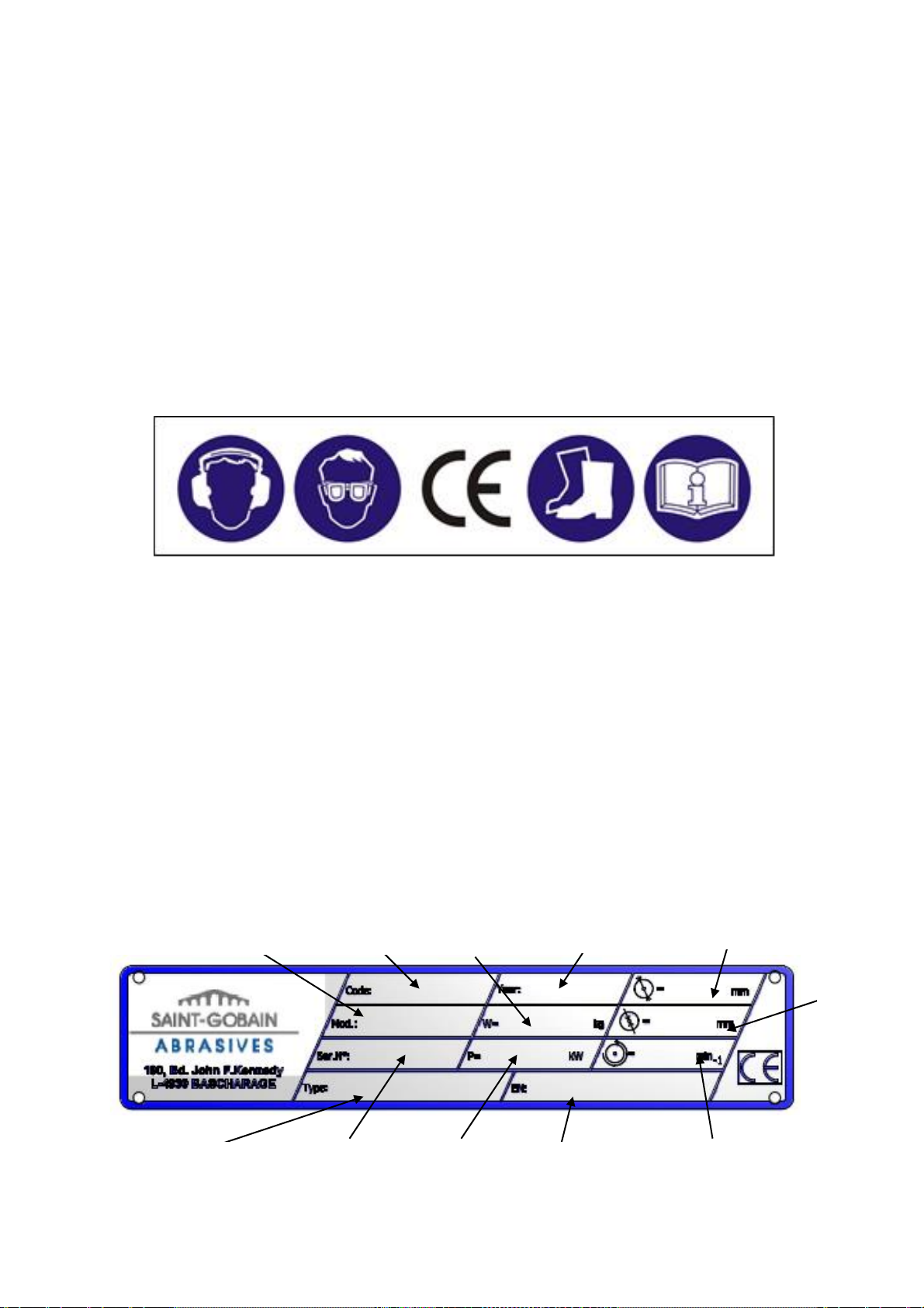
Please wear safety glasses when working.
Only use tools polishing or surfacing NORTON. The use of other tools may result in
damage to the machine.
Do not leave the machine resting on the tool or on the flexible coupling when she's not in
use, this would cause the premature deformation of the flexible coupling.
Chock in this case the machine on the handle.
!!! Never use the machine in the rain !!!
Machine with electric motor
Turn off the power supply to the CG 252 and separate it from the network before any
operation on the machine.
Avoid contact of the electrical connections with the projections of water or moisture.
The CG 252 absolutely must be correctly connected to the earth. In case of doubt, made
Check the electrical connections by a qualified electrician.
In case of emergency you can stop the machine by pressing the button "Red" stop of the
electric box.
If the CG 252 stops without apparent reason, turn off the main supply power in electricity
of the machine. Only a qualified electrician is empowered to investigate and resolve the
problem.

VERS. 2017.06.01. CG 252_MAN_EN
7
2 MACHINE DESCRIPTION
Any modification to the machine which can altering these initial properties can be carried out
only by Saint-Gobain abrasive, only one to confirm the conformity of the product. Saint-
Gobain Abrasive retains the right to make any technical change or the design of the machine
without prior notification.
2.1 Short description
The polisher grinder CG 252 is designed for the preparation of small and medium surfaces.
Robust and powerful Machine, she can be used on construction sites, but also in industrial
environment.
2.2 Purpose of use
The CG 252 is designed for the preparation of soils (sanding, preparation before installing
coating, rectification, deletion of irregularities or glues etc…). she's designed for no other
use.
Overview of the components

VERS. 2017.06.01. CG 252_MAN_EN
8
Handle of use and arm (1)
Rigid construction in welded steel.
The angle of the arm can be adjusted to guarantee a comfortable use.
Enclosure to On/Off Button (2)
This unit is made up of start buttons (Black) / Stop (red) which allow start and stop the
machine. The stop button (red) is an emergency stop button.
Electric motor (3)
Electric Motor 230V 1~ / 2,2kW.
Lifting Handle (4)
The lifting handle allows you to lift the machine by hand.
Flexible Coupling (5)
The flexible coupling is a vital part of the machine it ensures the connection between the
engine and the polishing or surfacing tool.
Protective casing (6.1)
The protective casing sliding protects the operator from the rotation of the polishing or
surfacing tools, while giving him an optimal view on the advance of his work.
Removable protective casing (6.2)
This protective casing is removable to allow work in a flush to the wall.
Suction Hose (7)
Hose for dust extraction.
Hose for supply in water (8)
Hose for supply in water.
Connection nozzle for dust extractors (9)
This nozzle allows you to connect a dust extractors CLIPPER during a dry use.
Indexable lever to tilt the machine (10)
This lever allows you to release the handle allowing the inclination of the machine.
Handle tilt of the machine (11)
Turn the handle to adjust the tilt angle of the machine according to your needs.
Indexable Lever for the rotation of the head (12)
This lever allows you to release the front head of the machine for rotate it, when you need to
use it in a flush to the wall
Adjustment of the rear track of the machine (13)

VERS. 2017.06.01. CG 252_MAN_EN
9
This setting allows you to widen the rear track depending on the needs for better stability.
2.3 Technical Data
Electric motor
2,2 kW / 3HP / 230V 1~
Electric motor protection
IP54
Maximun tool Diameter (Discs)
250mm
Rotation speed of the output shaft of
the reducer
1410 Tr.min-1
Sound level
79 dB (A) (according to ISO EN 11201)
Sound Power Level
91 dB (A) (according to ISO EN 3744)
Typ of tool
Polishing or surfacing tool
Machine Dimensions unfolded
(LxWxH)
1180x420x1120mm
Machine Dimensions folded
(LxWxH)
800x420x860mm
Weight (with tool assembled)
60 kg

VERS. 2017.06.01. CG 252_MAN_EN
10
2.4 Statement regarding the vibration emission
Declared value of vibration emission following EN 12096, EN ISO 20643 and
EN ISO 5349.
Machine
Model / code
Measured value of vibration
emission at m/s2
Uncertainty K
m/s2
Tool used
Model / code
CG 252
70184694290
<2.5
0.5
Diamond plates
GRD25 S MEDIUM
Green
70184627119
The vibration value is lower and does not exceed 2.5 m/s².
The measurements are made with new machines. Actual values may vary with site
conditions, in terms of:
Materials worked
Wear Machine
Lack of maintenance
Inappropriate tool for application
Tool in poor condition
Unskilled operator
Etc…
The exposure time to vibration is based on the performance of work (related to the
adequacy Machine / Tool / worked material / operator)
When evaluating risks due to hand-arm vibration, you need to take into account effective
usage at rated power of machine during a full day of work; quite often you will realise that
effective utilisation time represents around 50% of overall duration of work. You have to
consider, of course, breaks, water feeding, preparation of work, time to move the
machine, disk mounting…

VERS. 2017.06.01. CG 252_MAN_EN
11
2.5 Statement regarding noise emission
Declared value of noise emission following EN ISO 11201 and NF EN ISO 3744.
Machine
Model / code
Sound
Pressure level
LPeq
EN ISO 11201
Uncertainty K
(Sound
Pressure level
LPeq
EN ISO 11201)
Sound power
level
LWeq
NF EN ISO 3744
Uncertainty K
(Sound power level
LWeq
NF EN ISO 3744)
CG 252
70184694290
79 dB(A)
2.5 dB(A)
91 dB(A)
4 dB(A)
The measurements are made with new machines. Actual values may vary with site
conditions, in terms of:
Wear Machine
Lack of maintenance
Inappropriate tool for application
Tool in poor condition
Unskilled operator
Etc…
Measured values relate to an operator in normal use, as described in the manual
position.

VERS. 2017.06.01. CG 252_MAN_EN
12
3 ASSEMBLY AND COMMISSIONING
The machine is delivered assembled, fully equipped and ready for use. Before using the
machine for the first time, follow these simple instructions.
3.1 Tool assembly
Only use tools NORTON. The machine can be used with tools of types: discs, wings.
Turn off the power of the machine and unplug there of the electrical network prior to install or
change a tool. The maximum diameter of tools supported by the machine is 250mm.
To mount a tool, lay the machine so for it rests on its sleeve. (Handle to the ground).
Make sure that the machine will not tip, then mount and tighten your tool.
3.2 Establishment of connections
Check that :
The button "start" (Black) to start is not activated.
The supply voltage and the current type correspond to those of the machine.
Grounding is regulatory.
The power cable is at least 2.5 mm2 of section by phase.
3.3 Establishment of the dust extractors.
During a dry use always use the machine with a dust extractors. A nozzle of connecting at
the level of the frame is provided for this purpose. You simply connect the dust extractors on
this nozzle.
3.4 Establishment of the water supply
A nozzle of connection is provided for a use at the water. You simply connect your arrival of
water on this nozzle. A valve is located downstream of this nozzle to regulate the flow.
3.5 Starting the machine
Turn the guide arm in a comfortable position. To do this, loosen the screw on the
articulation of the arm, turn the arm to the desired angle, and tighten the screw.
Then, adjust the wheel spacing of the rear track according to your needs.
For a dry use, always use a dust extractors.
Connect the pipe of the dust extractors to the machine nozzle provided for this purpose,
then start the dust extractors before starting the machine.
For use with water, open the valve located on the machine to regulate your flow.
You can also connect a dust extractors for a used at the water. To do this connect the
pipe to the dust extractors to the machine nozzle provided for this purpose, and then start
the dust extractors before starting the machine.
Stay behind the machine and then lift the machine off the ground and assuring you that
the polishing or surfacing tool isn't in contact with the ground. Make sure that the protective
casing remains in contact with the ground.
To start the machine, press the button "start" (black).
Start the job by lowering the machine until the tool work effectively on the ground.
To stop the machine, press the button "Stop" (red).
Unplug the machine from the electrical network and wait for the complete shutdown of
the work tool.

VERS. 2017.06.01. CG 252_MAN_EN
13
Turn off the dust extractors and or the water valve.

VERS. 2017.06.01. CG 252_MAN_EN
14
4 TRANSPORT AND STORAGE OF THE MACHINE
4.1 Security for transport
Always disassemble the tool of polishing or surfacing before the transport or movement of
the machine.
4.2 Transport procedure
Conform yourself to work regulations, in order to transport the machine. The machine is not
designed to be lifted with a crane.
A carrying handle is provided, for the manual transport.
4.3 Storage of machine
If the machine is not going to be used for a long period, completely clean the machine and
disassemble the tool of polishing or surfacing. The storage site must be clean, dry and at a
constant temperature.

VERS. 2017.06.01. CG 252_MAN_EN
15
5 OPERATING THE MACHINE
In this section you will find tips for using the machine safely.
5.1 Site of work
Remove from the site anything, which might hinder the working procedure!
Make sure the site is sufficiently well lit!
Observe manufacturer's conditions for connecting to power supplies!
Place the electrical cables, the water pipe so as to avoid the possibility of fall and
damage.
Make sure you have a continual adequate view of the working area so you can
intervene in the working process at any time!
Keep other staff out of the area, so you can work securely.
5.2 Specific Adjustment of the machine
To adjust the pressure and the attack of the tools on the ground, you can simply loosen
the indexable joystick and turn the handle then adjust the position of the axis according to
your needs (see photo below).
To adjust the spacing of the wheels of the rear track of the machine it you simply loosen
the screw at the level of the axis of the wheel with the key provided with the machine.
Then adjust the spacing according to your needs for a better stability (see photo below).

VERS. 2017.06.01. CG 252_MAN_EN
16
The machine offers a possibility of easy maneuvering by twisting the head of polishing
following the desired angle.
To do this loosen the indexable joystick (1) then rotate the head to the desired angle
depending on the index holes available (2).
The good chosen position, tighten the indexable joystick (1) (see photos below).
When a job in a flush to the wall is necessary so you can rotate the head to the desired
angle, but you must also remove the removable cover (3) via its two mounting screws
(see photos below), a surplus of dust is possible.

VERS. 2017.06.01. CG 252_MAN_EN
17
!!! Warning, danger !!! :
When a used in a flush to the wall , removable casing protective removed, all person must
stand behind the machine for security!!! All person not complying with this setpoint is
exposed to a risk and will be in danger.
Machine without removable protective casing

VERS. 2017.06.01. CG 252_MAN_EN
18
5.3 Polishing and preparation of the ground with the CG 252
To use the CG 252 properly, you must stand behind the machine, taking the two
handles.
To start the machine, press the button "start" (black).
To stop the machine, press the button "Stop" (red).
To get an optimal result during the work of the machine, the machine must not stagnate
in a point, on the contrary, it must be in perpetual motion following the diagram
recommended below:
Machine Guidance
Move the machine from left to right and from the front toward the rear.
NOTE: never leave the machine to turn in continuous on the same place under penalty of
degrade seriously the ground.
WARNING: after the extinction of the machine, the tool continuous to turn up to his full stop.
So, be vigilant to avoid any injury.

VERS. 2017.06.01. CG 252_MAN_EN
19
6 MAINTENANCE AND SERVICING
In order to maintain a quality in time, during the preparation of your floors and for a safe
operation and without any problems of the machine, please follow the maintenance plan
below:
Begin of the day
During the changing of
tool
End of the day
or more often if required
Every week
After a fault
After a damage
Machine assembly
Contrôle visuel (état
général, étanchéité)
Clean
Tool and removable casing
Clean
Motor cooling fan
Clean
Motor housing
Clean
Reachable nuts and screws
Tighten up
Maintenance of the machine
Always perform the maintenance of the machine with the machine isolated from the
electrical supply and with tools idle.
Lubrication
The NORTON machines are equipped with bearings lubricated for life. It is therefore
unnecessary to grease or oil the machine, except the places fitted with a grease fitting.
Check and change of the flexible coupling
To check the condition of the flexible coupling you can simply proud you to the wear of your
tool. If you notice a wear not uniform on the tool (part of beveled tool), see traces more
pronounced on your ground it may be time to replace the flexible coupling.
In effect this are the first causes directly related to the wear of the flexible coupling.
To change the flexible coupling disconnects the machine from the electrical network and
then chock the machine to the change tool position (section 3.1).
Disassemble the tool in loosening the appropriate screws, and then remove the protective
casings and loosen the screws of the bracket plate and of the flexible coupling.
Replace then with a new flexible coupling, and then reassemble the while taking care to
reassemble the protective casings while checking their proper functioning.
Cleaning of the machine
Your machine will last longer if you clean it thoroughly after each day of work.

VERS. 2017.06.01. CG 252_MAN_EN
20
7 FAULTS : CAUSES AND CURES
7.1 Fault-finding procedures
Should any fault occur during the use of the machine, turn it off, and isolate it from the
electrical supply. Any works dealing with the electrical system or supply of the machine can
only be carried out by a qualified electrician.
7.2 Trouble-shooting guide
Panne
Source possible
Résolution
The engine is not
running when the button
"Start" (black) is
pressed.
No electricity
Check the electrical supply
(fuse for example)
Connection cable section too
small
Change connection cable
Defective switch
CAUTION : can only be solved
by qualified electrician
Defective motor
Change motor or contact motor
manufacturer
Defective connection cable
Change connection cable
7.3 Circuit diagram
1 : Control Box
Table of contents
Popular Grinder manuals by other brands

Henry Airtools
Henry Airtools 56 VL General safety and maintenance manual

Cleco
Cleco 1700 Series Operation & service manual

Yamato
Yamato CSA 20L 115 instruction manual

Jet
Jet JNS-7034 Operating and maintenance instructions

Bosch
Bosch Professional GCO 220 Original instructions

Makita
Makita 9561CR instruction manual