BILT HARD TL-GD-6L User manual

226002
6 INCH BENCH GRINDER
INSTRUCTION MANUAL
Thank you for ordering our product. If you have any issue,
or call (888) 680-2849

Specifications 2
Safety guidelines 3
Package contents 8
Assembly
9
Operation
11
Maintenance
12
Exploded view 14
Parts list
15
Motor
Speed (no load) 3450 RPM 3450 RPM
TL-GD-6L TL-GD-6SD
Wheel Size 6 x 3/4 x 1/2 inch
Wheel Grits #36 (Coarse)/ #60 (Medium)
Work Stand YesNo
Lamp 40W MAX (Bulb not included)
6 x 3/4 x 1/2 inch
#36 (Coarse)/ #60 (Medium)
40W MAX (Bulb not included)
SPECIFICATIONS
TABLE OF CONTENTS
..................................................................
..............................................................
.............................................................
..........................................................................
.........................................................................
....................................................................
..................................................................
.........................................................................
Troubleshooting
16
................................................................
2

SAFETY GUIDELINES
3
Safety is a combination of common sense, staying alert and knowing how your
item works.
SAVE THESE SAFETY INSTRUCTIONS.
WARNING: Read all safety warnings and all instructions. Failure to follow
the warnings and instructions may result in electric shock, fire and serious
injury. To avoid mistakes and serious injury, do not plug in your tool until t
he following steps have been read and understood.
WORK AREA SAFETY
1. Keep work area clean and well lit. Cluttered or dark areas invite accidents. Do not
work on floor surfaces that are slippery with sawdust or wax. Keep the ground clear
of tripping hazards.
2. Do not operate power tools in explosive atmospheres, such as in the presence of
flammable liquids, gases or dust.Power tools create sparks which may ignite the
dust or fumes.
3. Keep bystanders at a safe distance from the work area. Never allow children or pets
near the tool.
ELECTRICAL SAFETY
1. Do not expose power tools to rain or wet conditions. Water entering a power tool will
increase the risk of electric shock.
2. Power tool plugs must match the outlet. Never modify the plug in any way. Modified
plugs with non-matching outlets will increase the risk of electric shock.
3. Check all power supplies periodically. Do not use defective cords. Damaged or
entangled cords increase the risk of electric shock. Never use the cord for carrying,
pulling or unplugging the power tool. Keep cord away from heat, oil, sharp edges, or
moving parts.
PERSONAL SAFETY
1. Stay alert. Watch what you are doing and use common sense when operating a power
tool. Do not use a powertool while you are tired or under the influence of drugs, alcohol,
or medication. A moment of inattention while operating power tools may result in serious
personal injury.
2. Do not wear loose clothing, gloves, neckties, or jewelry (rings, watches, etc.) when
operating the tool. Inappropriate clothing and items can get caught in moving parts
and draw you in. Always wear non-slip footwear and tie back long hair.
3. Use personal protective equipment. Always wear safety goggles at all times that comply
with ANSI Z87.1. Use ear protection such as plugs or muffs during extended periods
of operation. Wear work gloves to protect your hands. Wear a face mask or dust mask
to fight the dust.
4. Keep proper footing and balance at all times and do not overreach when operating the
power tool.

4
WARNING: Dust generated from certain materials can be hazardous to your
health. Always operate the tool in a well-ventilated area and wear a dust mask.
Use dust collection systems when processing wood and plastics. Dust
extractors or dust bags must not be connected when processing metals.
POWER TOOL USE AND CARE
1. Avoid accidental start-ups. Make sure the power switch is in the OFF position before
connecting the plug to a power source or carrying the tool.
2. Check power tool for damaged parts. Check for misalignment of moving parts, amming,
breakage, improper mounting, or any other conditions that may affect the tool’s
operation. Do not use the power tool if the switch does not turn ON/OFF. Any part
that is damaged should be properly repaired or replaced before use.
3. Do not force the tool to do a job for which it was not designed. Use the correct power
tool and accessories and follow the instructions for your application to prevent
hazardous situations.
4. Remove adjustment tools. Always make sure all adjustment tools or wrenches are
removed from the tool before turning on the power tool.
5. Keep guards in place and in working order before operating the tool. All protection
and safety devices must be in place after completing repair and maintenance
procedures.
6. Never leave a running tool unattended. Do not leave the tool until it has come to a
complete stop.
CALIFORNIA PROPOSITION 65 WARNING
This product and some dust created by power sanding, sawing, grinding, drilling, and
other construction activities may contain chemicals, including lead, known to the State
of California to cause cancer, birth defects, or other reproductive harm. Wash hands
after handling.
Some examples of these chemicals are:
• Lead from lead-based paints.
• Crystalline silica from bricks, cement, and other masonry products.
• Arsenic and chromium from chemically treated lumber.
POWER TOOL MAINTENANCE
1. Always disconnect the power cord plug from the electrical outlet when making adjust-
ments, changing parts, or storing power tools. Such preventive safety measures
reduce the risk of starting the power tool accidentally.
2. Maintain power tools properly. Safely store power tools out of the reach of children.
Always keep tools clean and in good working order. Follow instructions for lubricating
and changing accessories.
3. Only have your power tool serviced by a qualified repair person using only identical
replacement parts. Use of any other part can cause personal injury and damage to
the tool.

5
WARNING: Do not plug in or operate this tool until the entire manual has
been read and understood.Failure to do so may result in personal injury or
machine damage.
1. Use only the correct grinding wheels that meet the following requirements:
• The speed rating of the wheel is greater than 3450 RPM.
• The wheel complies with ANSI B7.1.
• The size of the wheel is 6 inches in diameter and 3/4 inch thick with a 1/2-inch arbor.
Do not use wheels with incorrect arbor size.
2. Always inspect grinding wheels prior to use for cracks or missing pieces. If imperfec-
tions are present, replace wheel immediately before use. Never use wheel washers
or screws that are defective or incorrect.
3. Thoroughly inspect the grinder. Do not use the bench grinder if the flange nut or arbor
hex nut is missing or if the spindle shaft is bent. Use only flanges furnished with this
bench grinder.
4. Never touch a grinding wheel or other moving parts during operation or immediately
after use. It takes approximately 3 minutes for the wheels to come to a stop after the
tool is switched off.
5. Do not overtighten the wheel nut. Do not use an impact wrench to make adjustments
to the grinding wheel nuts,as it could cause damage to the wheel, which could cause
severe injury.
6. Risk of injury due to accidental starting. Do not use in an area where children may be
present.
7. Always secure the bench grinder by bolting it down to its supporting surface to prevent
the grinder from tipping over, sliding, or walking during operation.
8. Do not remove the wheel guard, unless changing a grinding wheel. Ensure the cover
is replaced before using the grinder. Always use the guards, spark deflectors and eye
shields during operation.
9. Check the ON/OFF switch of your tool. Do not use tool if switch does not turn it on
and off. Have defective switches replaced by an authorized service center.
10.Stand beside the bench grinder during start-up, not directly in front. Never stand or
have any part of your body in line with the path of the wheel.
11.Never start the grinder when the wheel is in contact with the workpiece.
12.Always hold the workpiece firmly against the work rest.
13.Always ease the workpiece against the abrasive wheel when starting to grind.A harsh
impact can break the wheel.Use light pressure when starting to grind. Too much
pressure on a cold wheel can cause the wheel to crack.
14.Do not use the grinding wheel to cut anything.
15.Do not apply excess stress to the grinding wheel. Excessive pressure may damage
the tool, cause the motor to overheat, and prematurely wear down the grinding wheel.
16.New wheels may require dressing to make them round. Use a grinding wheel dress-
ing tool (not included) to shape or remove glaze from grinding wheels.
Your risk from these exposures varies depending on how often you do this type of work.
To reduce your exposure to these chemicals, work in a well-ventilated area with approved
safety equipment such as dust masks specially designed to filter out microscopic particles.

6
GROUNDING INSTRUCTIONS
IN THE EVENT OF A MALFUNCTION OR BREAKDOWN,grounding provides the path of
least resistance for an electric current and reduces the risk of electric shock. This tool
is equipped with an electric cord that has an equipment grounding conductor and a
grounding plug. The plug MUST be plugged into a matching outlet that is properly
installed and grounded in accordance with ALL local codes and ordinances.
DO NOT MODIFY THE PLUG PROVIDED. If it will not fit the outlet, have the proper outlet
installed by a licensed electrician.
IMPROPER CONNECTION of the equipment grounding conductor can result in electric
shock. The conductor with the green insulation (with or without yellow stripes) is the
equipment grounding conductor. If repair or replacement of the electric cord or plug is
necessary, DO NOT connect the equipment grounding conductor to a live terminal.
CHECK with a licensed electrician or service personnel if you do not completely under-
stand the grounding instructions or whether the tool is properly grounded.
USE ONLY THREE-WIRE EXTENSION CORDS that
have threepronged plugs and outlets that accept
the tool’s plug as shown in Fig. 1.Repairor replace
a damaged or worn cord immediately.
CAUTION: In all cases, make certain the outlet in
question is properlygrounded. If you are not sure,
have a licensed electrician check the outlet.
17.Keep the distance between the wheel and tool rest at most a 1/8-inch (3.2 mm) space.
Adjust the work rest accordingly as the wheel grinds down to a smaller diameter with
use over time.
18.Guard against electrical shock by preventing body contact with grounded surfaces.
For example: pipes, radiators,ranges, refrigerator enclosure, etc.
19.Never reach to pick up a workpiece, a piece of scrap, or anything else that is in or near
the grinding path of the wheel.
20.Avoid awkward operations and hand positions where a sudden slip could cause your
hand to move into the wheel. Always make sure you have good balance.
21.Do not turn the switch on and off rapidly. This could cause the wheel to loosen and
create a hazard. Should this ever occur, stand clear and allow the wheel to come to
a complete stop. Disconnect your grinder from the power supply and retighten the wheel
nut securely.
22.Frequently clean grinding dust from beneath the grinder.
23.If any part of this grinder is missing, broken, bent, or damaged in any way, or if any
electrical component fails to perform properly, shut off the power switch, remove the
machine plug from the power source and have the damaged, missing, or failed parts
replaced before operation.
Electrical information

7
WARNING: This tool is for indoor use only. Do not expose to rain or use in
damp locations.
WARNING: This tool must be grounded while in use to protect the operator
from electric shock.
EXTENSION CORD GUIDELINES
Make sure your extension cord is in good condition. When using an extension cord, be
sure to use one heavy enough to carry the current your product will draw. An undersized
cord will cause a drop in line voltage resulting in loss of power and overheating. The table
below shows the correct size to be used according to cord length and nameplate ampere
rating. When in doubt, use a heavier cord. The smaller the gauge number, the heavier
the cord.
Make sure your extension cord is properly wired and in good condition. Always replace
a damaged extension cord or have it repaired by a qualified person before using it.
Protect your extension cords from sharp objects, excessive heat and damp/wet areas.
Use a separate electrical circuit for your tools. This circuit must not be less than a #12
wire and should be protected with a 15 A time-delayed fuse. Before connecting the motor
to the power line, make sure the switch is in the OFF position and the electric current is
rated the same as the current stamped on the motor nameplate. Running at alower
voltage will damage the motor.
AMPERAGE
2.1A
REQUIRED GAUGE FOR EXTENSION CORDS
25ft.
18 guage 16 guage 16 guage 14 guage
50ft. 100ft. 150ft.
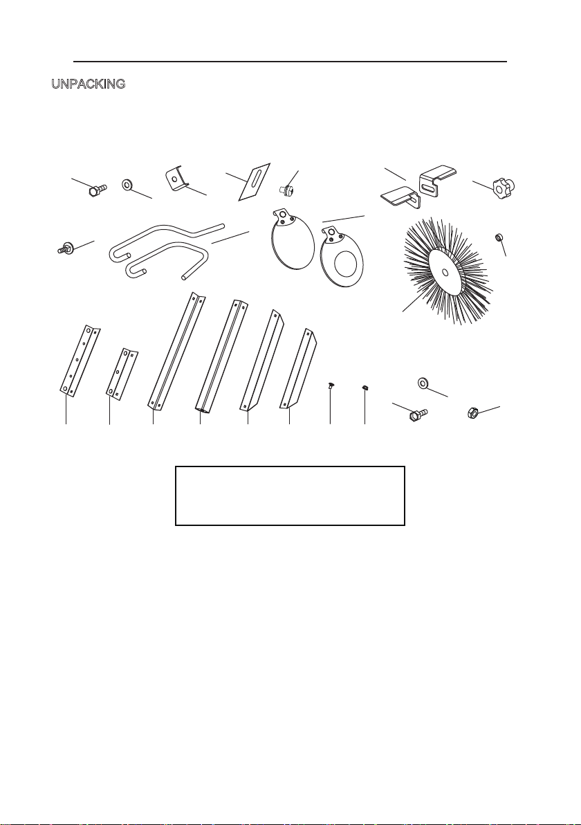
PACKAGE CONTENTS
8
G
D
I
J
C
A
W
B
K
F
E
H
Safety shield (2)
A - Hex head bolt (2)
B - Washer (2)
C - Clamp bracket (2)
D - Spark deflector (2)
E - Screw assy (2)
F - Work rest (2)
G - Work rest knob (2)
H - Carriage bolt (2)
I - Shield rod (2)
J - Safety shield (2)
K - Wire wheel (1)
L - Spacer (1)
M - Washer (8)
N - Hex nut (4)
UNPACKING
This product requires assembly.
■ Carefully remove the tool and any accessories from the box. Make sure that all items
listed in the Loose Parts are included.
O VP Q R T US
O - Top Long Bar (2)
P - Top Short Bar (2)
Q - Upper Leg (4)
R - Under Leg (4)
S - Middle Long Bar (2)
T - Middle Short Bar (2)
U - Small Round Head Bolt (16)
V - Hex Flange Nut (16)
W - Hex head bolt (4)
TL-GD-6L:A--L
TL-GD-6SD:A--Y
Including accessories:
L
MN
ASSEMBLY
9
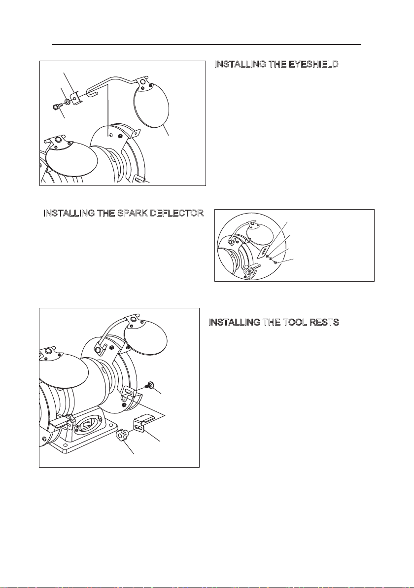
Tool rest
Carriage bolt
Tool rest knob
INSTALLING THE TOOL RESTS
1. Place the right tool rest over the tool rest
bracket and align the slots.
2. Slide the carriage head tool rest screw
through from the left side. Screw the tool
rest knob onto the carriage bolt to hold
the tool rest in place.
3. Adjust the tool rest within 1/16 inch of the
grinding wheel.
To adjust: loosen the knob, shift the tool
rest, then, tighten the knob.
4. Repeat on the left side.
I
O
Washer
Hex head bolt
Clamp bracket
Eye shield
INSTALLING THE EYESHIELD
1.Attach the right eye shield arm to the
bench grinder using the bracket, flat
washer and bolt supplied.
2. Fit the lens to the lens holder as shown.
3. Repeat for left side eye shield.
NOTE: Adjust the eye shields to an
appropriate distance from the tool rests
avoiding interference during operation.
1.Place the spark deflector against the wheel
guard and secure into place using a screw.
Adjust the spark deflector within 1/16”
(0.0625") ofthe grinding wheel and tighten
the screw.
Spark deflector
Phillips head screw
Lock washer
Washer
INSTALLING THE SPARK DEFLECTOR
ASSEMBLY
10
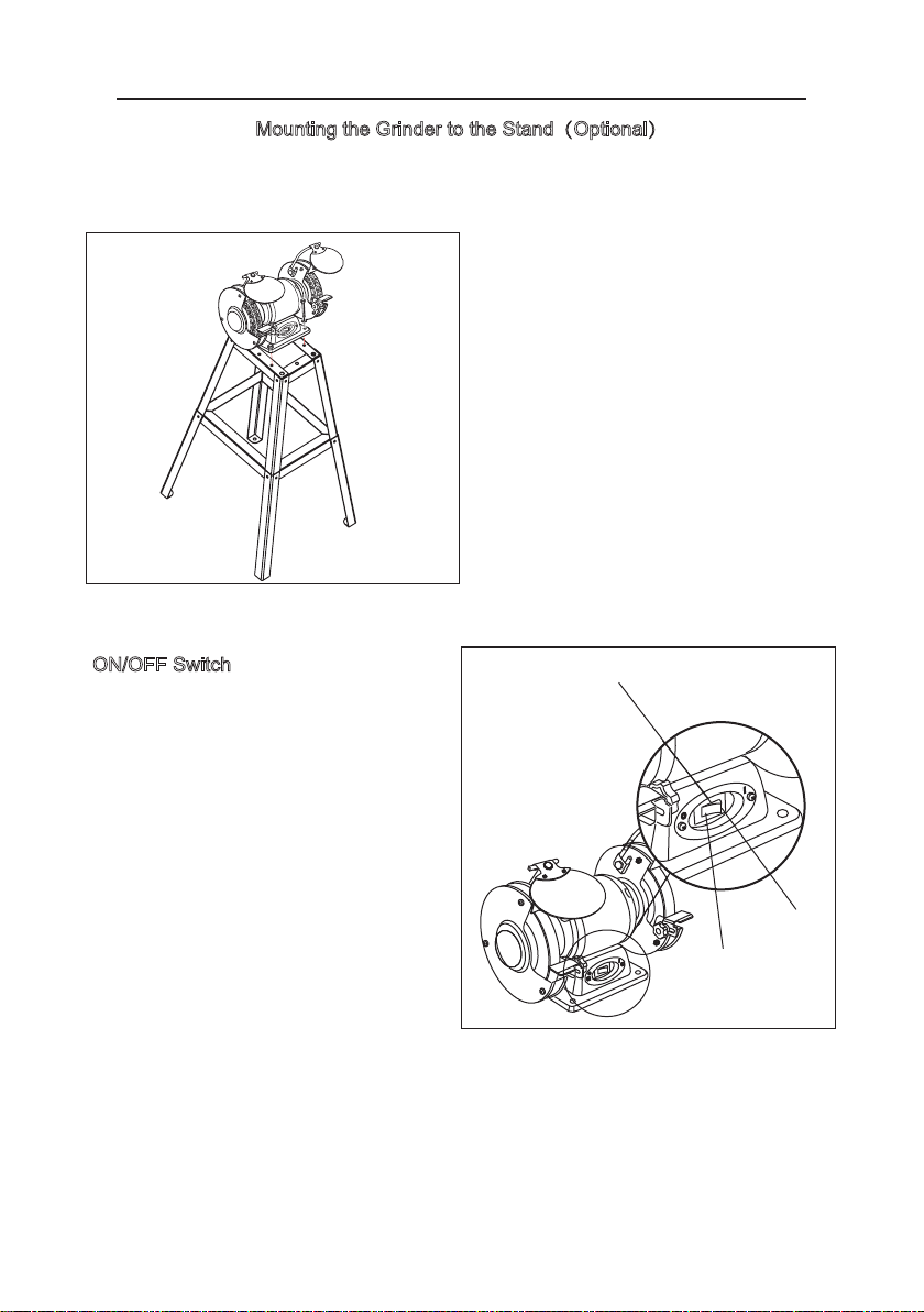
Mounting the Grinder to the Stand(Optional)
YOU MUST MOUNT YOUR BENCH GRINDER FIRMLY TO YOUR STAND, GRINDING
STAND, OR OTHER RIGID FRAME BEFORE YOU OPERATE IT.
1. Make sure the bench grinder is turned
off and unplugged.
2. Position the grinder on the stand in a
safe location. Make sure that the power
cord will reach an appropriately
grounded outlet.
3. Matching up the mounting holes in the
grinder base to the drilled holes in the
stand.
4.Using bolts, washers, lock-washers and
nuts, as shown, secure the grinder to
the stand.
Off
On
On/Off Switch
ON/OFF Switch
1. Press the power switch side marked
“I” to turn the grinder on.
2. Press the power switch side marked
“0” to turn the grinder off.
I
O

OPERATION
11
WARNING: STAND TO ONE SIDE OF THE GRINDER AND SWITCH IT ON.
LET THE GRINDER OPERATE AT FULL SPEED FOR ONE MINUTE SO THAT
ANY UNDETECTED FLAWS OR CRACKS OF THE WHEEL WILL BECOME
APPARENT. MAKE SURE THAT THE BENCH GRINDER IS OPERATING
PROPERLY, WITH NO EXCESSIVE VIBRATION OR OTHER PROBLEMS.
WARNING: IF THERE IS ANY ABNORMALITY IN THE WAY THE BENCH
GRINDER OPERATES, TURN IT OFF IMMEDIATELY AND DO NOT USE IT
UNTIL THE PROBLEM IS FIXED OR THE GRINDER IS SERVICED.
WARNING: THE GRINDING WHEELS CONTINUE TO ROTATE AFTER THE
TOOL IS SWITCHED OFF. WAIT FOR THE WHEEL TO COME TO A COM-
PLETE STOP.
1. With the power cord unplugged, perform safety inspections:
• Make sure the work area is safe and clean.
• Make sure the wheel is in good condition.
• Make sure the guards are in place and in working order.
• Make sure the guards are set at the proper distance from the wheel.
• Make sure that the wheel will not contact any components of the bench grinder.
• Wear appropriate protective equipment. Refer to the Important Safety Instructions
of this manual.
2. Make sure the power switch is OFF.
3. Plug in the bench grinder.
4. Turn the power switch ON.
5. When the bench grinder has reached full speed, grinding may be started.
• Place the workpiece on the tool rest.
• Move the workpiece into contact with the grinding wheel. Refer to Grinding Tips.
• Note: If the workpiece becomes hot, dip it into water or oil to cool it.
6. To turn off the bench grinder, switch it OFF.

MAINTENANCE
12
WARNING: For your own safety, turn the switch OFF and remove the plug
from the electrical outlet before adjusting or performing maintenance or
lubrication work on the grinder.
WARNING: Any attempt to repair or replace electrical parts on this tool may
be hazardous. Repairs should be done by a qualified service technician only.
Before using, check to make sure parts are not damaged, missing, or worn. Check for
alignment of moving parts,binding of moving parts, improper mounting, or any other
conditions that may affect the grinder’s operation. If any of these conditions exist, do
not use until parts are replaced or the grinder is properly repaired. Frequently blow or
vacuum dust from all surfaces and the motor housing.
GENERAL CLEANING AND MAINTENANCE
1. Regularly check the tool and use a soft brush to remove accumulated dust. Wear
safety goggles to protect your eyes while cleaning.
2. If the body of the grinder needs cleaning, wipe it down with a soft damp cloth. A mild
detergent can be used.Do not use alcohol, petrol, or other similar cleaning agents.
Do not make contact with the grinding wheels with any damp cloth.
3. Always make sure the eye shields are transparent and not blocking the view of the
grinding wheel.
4. In normal use, grinding wheels may become cracked, grooved, rounded at the edges,
chipped, out of alignment or loaded with foreign material. Cracked wheels should be
replaced IMMEDIATELY. While any of the other conditions can be remedied, new
wheels sometimes require dressing to make them round.
5. If you must replace a wheel be sure to obtain one with a safe rated speed at least
as high as the “NO LOAD” RPM marked on your grinder’s nameplate. Replacement
wheels must have a 6 inch diameter, a matching arbor size and should be a maximum
of 3/4 inch wide. Always check new wheels for cracks. Be sure the tool is unplugged
before attempting repairs and maintenance.
CAUTION: Never use caustic agents to clean the plastic parts of the tool. Water must
never come into contact with the grinder. The use of any other accessories is not
recommended and may result in serious injury.
POWER CORD REPLACEMENT
If replacement of the power supply cord is necessary, this must be done by an
authorized service center in order to avoid a safety hazard.
STORAGE
Store the bench grinder and the grinding wheels to prevent them from the potential
hazards of moisture, containments, and other damage.
MAINTENANCE
13
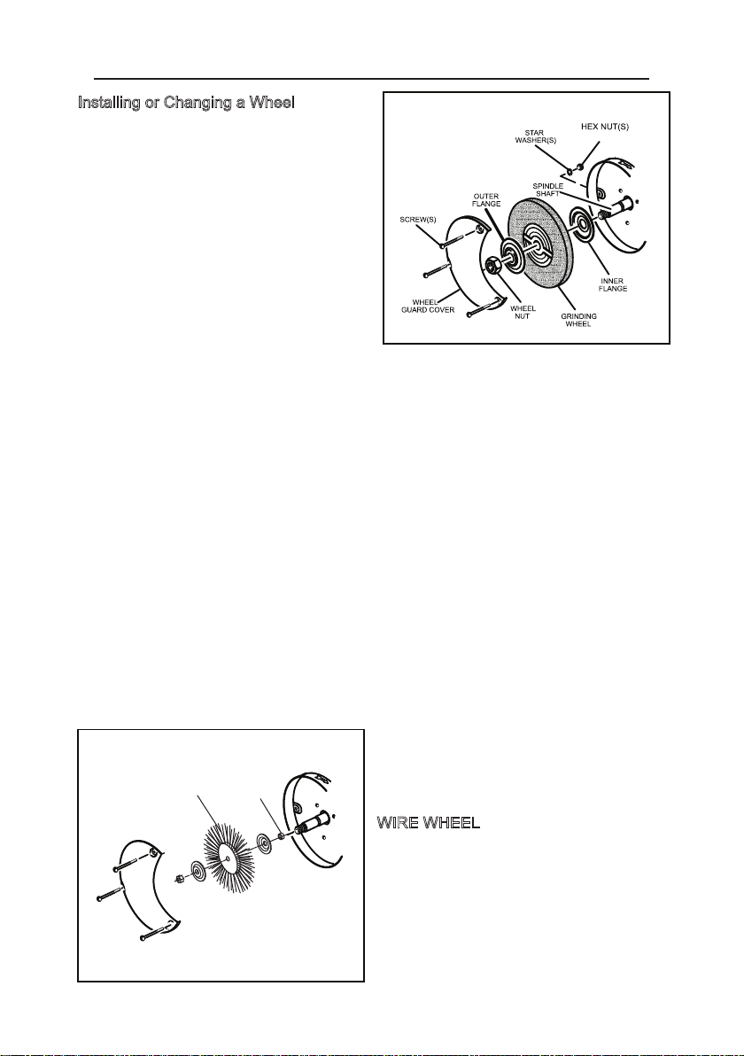
Installing or Changing a Wheel
1. Make sure the bench grinder is turned
off and unplugged.
2. Loosen the tool rest knob, and slide the
tool rest away from the wheel.
3. Loosen the spark deflector screw, and
remove the deflector.
4. Use a screwdriver to remove the three
wheel guard cover screws.
5. Remove the wheel guard cover.
6. Fit an appropriately sized wrench on
the wheel nut.
7. Loosen the wheel nut in a clockwise
direction for the left side and a counter-
clockwise direction for the right side.
8. Remove the nut, the outer flange and the grinding wheel from the spindle shaft.
9. Inspect the new wheel carefully to ensure
there are no cracks, chips or other damage.
10. Subject the grinding wheel to a “Ring Test”:
a. Make sure the grinding wheel is clean and free of dust and debris.
b. Suspend the wheel by its arbor hole and tap each of its four quadrants lightly
with a nonmetallic item.
c. If the wheel emits a ringing sound, it is in good condition. If the wheel emits a
dull sound, do not use the wheel. IT MAY BE CRACKED.
11. Place the ring-tested wheel and the outer flange on the spindle shaft.
12. Make sure the grinding wheel and outer flange are properly seated on the spindle
shaft.
13. Place the wheel nut on the spindle shaft.
14. Tighten the wheel nut in a counter-clockwise direction for the left side and a
clockwise direction for the right side.
15. Replace the wheel cover and attach the three guard cover screws.
WIRE WHEEL
A wire wheel can be used with your grinder.
You will need to add a spacer (as shown)
to allow the arbour hex nut to tighten correctly.
WIRE WHEEL
spacer
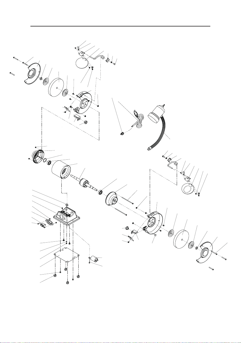
EXPLODED VIEW
14
1
2
3
20
7
7
8
9
10
13
14
15
17
18
19
17
14
21
22
23
24
25
26
25
27
28
29
30
33
34
29
49
48
25
26
25
24
47
22
46
45
32
32
11
6
5
4
12
10
16
30
31
38
39
37
51
50
13
35
41
42
43
44
43
42
41
40
38
39
37
36
13
35
34
31

PARTS LIST
15
NO.
1
2
3
4
5
6
7
8
9
10
11
12
13
14
15
16
17
18
19
20
21
22
23
24
25
26
NO.
27
28
29
30
31
32
33
34
35
36
37
38
39
40
41
42
43
44
45
46
47
48
49
50
51
Specification
Rubber foot
Philips screw+spring washer
assy M5×8
Philips screw+spring washer+
flat washer assy M4×7
Teeth washer D4
Philips screw+spring washer
assy M6×10
Philips screw M4×8
Switch
Switch plate
Hex nut M4
Base assy
Plug sleeve
Hex nut M4
Left end cap
Wave washer
Left work rest
Bearing
Stator
Rotor
Capacitor 8UF/300V
Philips screw+spring washer assy M4×120
Hex nut M5
Right inner guard
Philips screw+spring washer assy M5X10
flange
Wheel stone
QTY
4
2
1
1
1
2
3
1
1
3
1
1
6
2
1
1
2
1
1
1
2
6
1
4
4
2
Specification
Hex nut M12
Right guard cover
Philips screw M5×42
Lock handle
Spark deflector
Philips screw+spring washer+
flat washer assy M5×8
Right work rest
Bolt M6×14
Hex nut M6
Eyeshield pressing plate
Bolt M6X16
Philips screw M4X10
Right eyeshield support
Lock block
Flat washer D6
Hex bolt M6X14
Big lamp assy
Plug
Cord clip
Left inner guard
Hex nut M12
Left guard cover
Left eyeshield support
Eyeshield
QTY
1
1
6
2
2
2
1
2
2
1
2
2
4
1
2
2
2
1
1
1
1
1
1
1
1
Base cover
Magnifying eyeshield

TROUBLESHOOTING
16
PROBLEM / PROBABLE CAUSE REMEDY
1.Grinder not plugged in.
2.Low Voltage.
3.Open circuit in motor or loose
connections.
4.Blown fuse or breaker.
5.Cord damaged.
1.Plug in the grinder.
2.Check power source for proper voltage.
3.Inspect all lead connections on motor for loose or
open connections. (Send for Servicing)
4.Replace fuse or reset circuit breaker.
5.Have cord replaced by an authorized service center.
1.Motor overloaded.
2.Extension cord too long and of
insufficient gauge (weight).
1.Reduce load on motor.
2.Utilize an extension cord of appropriate gauge and
length or plug tool directly into outlet.
1.Feed rate too great. 1.Reduce the rate at which the workpiece is fed into
the working area of the tool (grinding wheel).
1.Impurity on surface of wheel.
2.Workpiece not being held tightly.
1.Dress the grinding wheel.
2.Use a holding device to more firmly retain the work-
piece.
1.Machine vibrating.
2.Workpiece not being held firmly.
3.Wheel face uneven.
4.Wheel is too hard..
1.Ensure machine is securely mounted on a solid
surface.
2.Use a holding device to firmly retain the workpiece.
3.Dress the grinding wheel.
4.Use softer wheel, or reduce the feed rate.
1.Short circuit in motor or loose
connections.
2.Low voltage.
3.Incorrect fuses or circuit
breakers in power line.
4.Motor overload.
1.Inspect connections on motor for loose or shorted
terminals or worn insulation. (Send for Servicing)
2.Correct low voltage conditions (for example:
improper extension cord length and/or gauge).
3.Install correct fuses or circuit breakers or plug tool
into an appropriate circuit, matched to an appropriate
fuse or breaker.
4.Reduce the load on the motor.
1.Improper type of grinding wheel.
2.Improper feed rate.
3.Coolant required.
1.Try wheels with softer bond or coarser grit.
2.Slow down the rate at which the workpiece is fed
into the wheel.
3.Introduce coolant.
1.Feed rate is too aggressive.
2.Wheel is soft.
3.Wheel diameter too small.
4.Bad wheel dressing.
5.Defective wheel bonding.
1.Decrease feed rate of workpiece into grinding wheel.
2.Select a grinding wheel with a harder bond of
material.
3.Replace wheel.
4.Dress the wheel.
5.DO NOT USE – return wheel to point of purchase.
1.Wheel is too hard.
2.Feed rate is too slow.
3.Bad wheel dressing.
4.Coolant required.
1.Select a grinding wheel with a softer bond of
material.
2.Increase the feed rate of the workpiece into the
grinding
3.Dress the wheel.
4.Introduce coolant.
This manual suits for next models
1
Table of contents
Popular Grinder manuals by other brands


Westfalia
Westfalia 84 66 72 Original instructions

Porter-Cable
Porter-Cable 7406 instruction manual

Makita
Makita 9556PB Specification sheet

Profitech Diamant
Profitech Diamant BS 250 instruction manual

Würth
Würth KNS 150-E Translation of the original operating instructions

Bosch
Bosch Professional GWS 6-100 S Original instructions

Bosch
Bosch PWS 7000 instructions

Ingersoll-Rand
Ingersoll-Rand 88V Series Product information

Diamond Tech International
Diamond Tech International Power Max II Operation manual

Rockwell
Rockwell RD2873 user manual

dumore
dumore 57 Series Parts list and operating instructions

Ryobi
Ryobi EAG2023CN Owner's operating manual