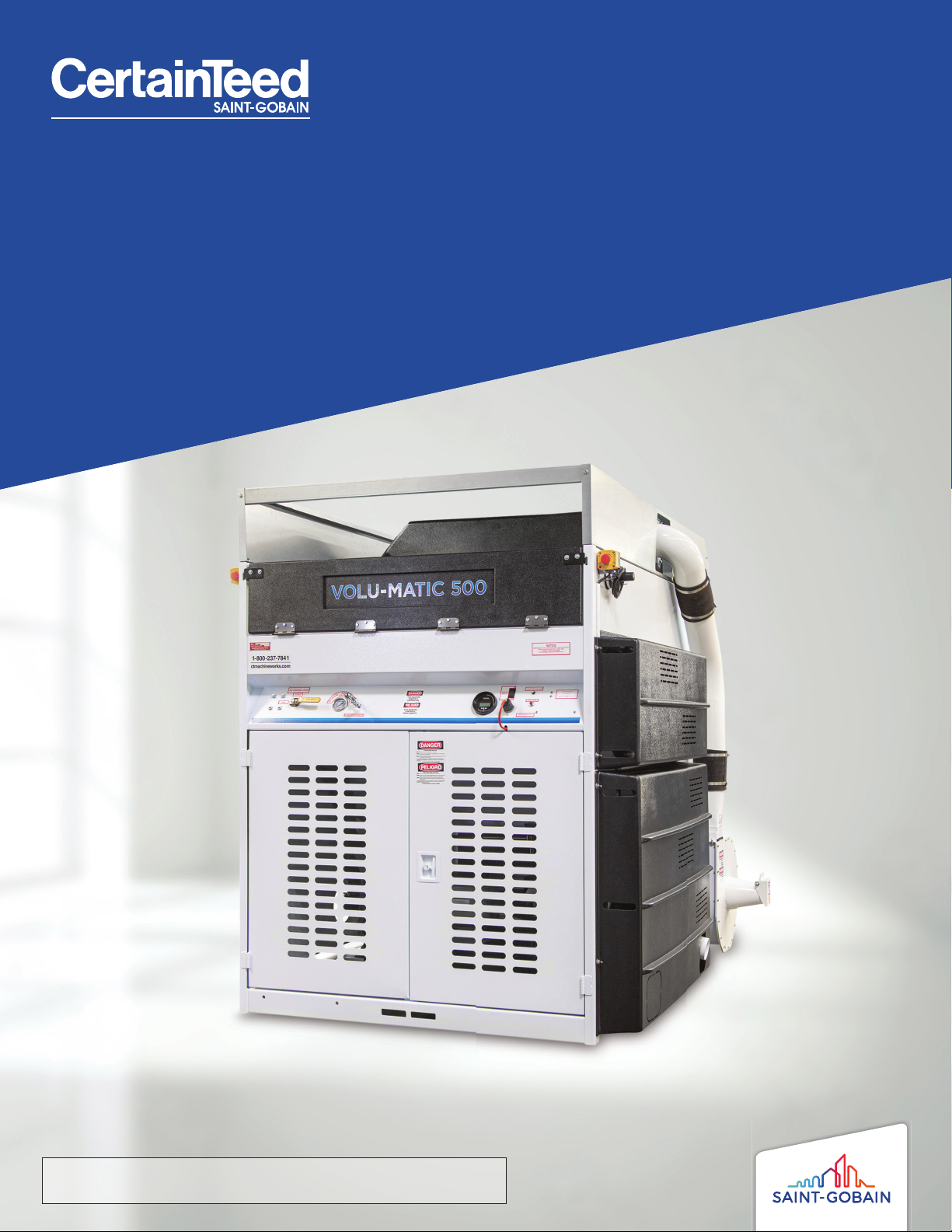
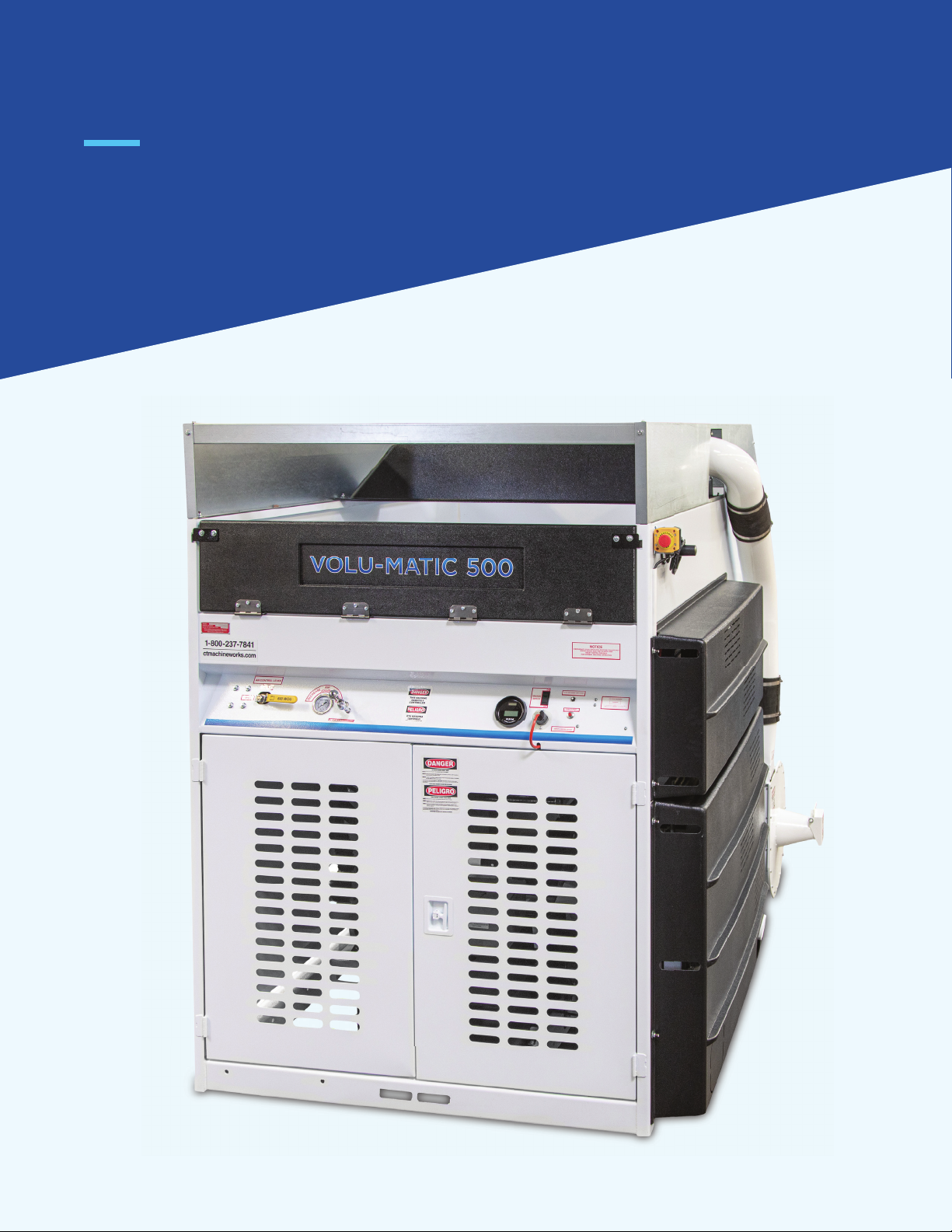
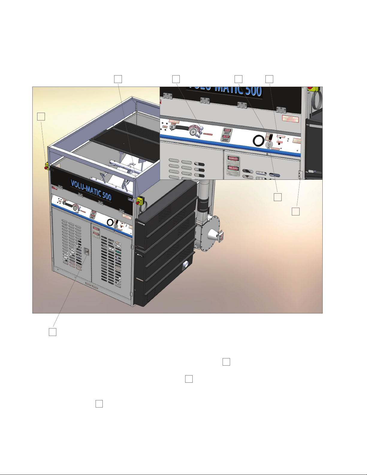
SAINT-GOBAIN CertainTeed Volu-Matic 500 Original instructions

1
Operation Manual
And Safety Information
Volu-Matic 500
Parts – Service – Accessories
863.294.3206 / 800.237.7841
www.certainteedmachineworks.com
PLEASE READ THIS MANUAL BEFORE PLACING YOUR NEW
VOLU-MATIC 500 INSULATION BLOWING MACHINE INTO SERVICE

2
WARNING
Carbon monoxide poisoning from engine exhaust
can be fatal. Make sure exhaust is routed away
from air intake flanges and that the truck body is
well ventilated.
WARNING
Recommended hose size, type, and length must be
used to achieve maximum results. CertainTeed
Machine Works cannot guarantee performance of
the Volu-Matic 500 machine if hoses are undersized,
worn, damaged, or hoses other than those we
recommend are used.
NOTE
Keep in mind that a weak truck battery may not be
powerful enough to run the machine. Keep the truck
battery and charging system in very good shape.
NOTE
A kit of decals for PTO installation is included
with new delivered machines. These decals should
be displayed on the truck as indicated by the
instructions provided with them.
Warning & Notes

3
SPECIFICATIONS................................................................................................................................................................4
ACCESSORY AND INSTALLATION KITS...................................................................................................................5
INTRODUCTION..................................................................................................................................................................6
SAFETY...................................................................................................................................................................................8
OPERATION........................................................................................................................................................................ 12
PREVENTIVE MAINTENANCE.................................................................................................................................... 24
TROUBLESHOOTING ..................................................................................................................................................... 38
PARTS DRAWINGS ......................................................................................................................................................... 42
PREVENTIVE MAINTENANCE RECORD................................................................................................................ 63
Table of Contents

4
Specifications
MODEL AVAILABLE:
Power Take-O on truck
FEATURES:
18" airlock feeder, air volume control system, electro-magnetic clutches, spiral bevel gearboxes,
four speed transmission, material recovery vacuum system, built-in water pump, built-in generator.
HEIGHT: 74"
LOAD HEIGHT: 60"
LENGTH: 88.5"
WIDTH: 80"
WEIGHT: 2500 lbs
ELECTRICAL: 12V remote control; 120V accessory power
BLOWER VOLUME: 270 cfm @ 2 psi
BLOWER PRESSURE: 6.0 psi maximum
VACUUM VOLUME: 600 cfm @ inlet cone
VACUUM PRESSURE: 4.5 inches of mercury @ inlet cone
MAXIMUM FEED RATES:
Cellulose: 70 - 80 lbs per minute @ 2.0 psi.
Fiberglass: 25 - 35 lbs per minute @ 3.5 psi.
Rockwool: 35 - 55 lbs per minute @ 4.5 psi.

5
P/N DESCRIPTION QUANTITY
ACCESSORY KIT
210955
Vacuum Wand - P/N 209388 1 EA
150 Foot Long Remote Control Cord – P/N 210893 1 EA
Operation Manual 1 EA
Stator Bar Cover Plate – P/N 210031 1 EA
INSTALLATION KIT*
211948
PTO Drive Belt Idler Support B - P/N 209899 1 EA
PTO Idler Roller Take Up Arm - P/N 209916 2 EA
Gearbox PTO Idler Spacer - P/N 210544 2 EA
3TB50 Pulley, (Uses P1 Bushing) - P/N 160263 1 EA
Bushing, Idler, 5/8" - P/N 162487 2 EA
Breaker, Circuit 20A - P/N 159034 1 EA
Blower Intake Truck Flange, 4.5 - P/N 209072 1 EA
4-1/2" Worm Drive Hose Clamp - P/N 162486 2 EA
4-1/2" CWC Spiral Hose - P/N 162380 3 FT
V.M. V PTO Tubular Drive Shaft - P/N 210486 1 EA
V5 Vacuum Idler Spacer-Washer - P/N 210551 1 EA
Gearbox PTO Idler Bracket Weld - P/N 210488 1 EA
2P5V44 Pulley - P/N 159775 1 EA
2Q5V75 Pulley (Q1 Bushing Req'd) - P/N 159777 1 EA
3TB64 Pulley (P1 Bushing Req'd) - P/N 160267 1 EA
P1 Bushing, 1-7/16" Bore - P/N 162596 1 EA
Q1 Bushing 1-7/16" - P/N 162640 1 EA
4" Worm Drive Hose Clamp - P/N 162485 2 EA
Holder, Circuit Breaker - P/N 162000 1 EA
P/B NonExp. Bearing 1-7/16" Bore - P/N 157713 1 EA
P/B Exp. Bearing 1-7/16" Bore - P/N 157715 1 EA
Accessory and Installation Kits

6
Introduction

7
VOLU-MATIC 500
The Volu-Matic 500 incorporates all of the standard features of the Volu-Matic 300 insulation blowing machine. All of
the hopper components, the shredder housing, and airlock feeder are identical. The machine also has the capability of
reclaiming all excess material at the point of delivery when spraying sidewalls. The hopper area has been expanded for
the introduction of these sprayed fibers with a self-contained vacuum system.
The Volu-Matic 500 machine is mounted in the back of the contractor's truck and is powered by the truck mounted PTO
box. This PTO box drives a shaft under the truck which has two belt drives up to the machine. One belt drive goes to the
rear of the machine that drives a gearbox which powers the vacuum and generator. An electro- magnetic clutch drives
the vacuum fan wheel shaft so that the vacuum can be o when blowing attics. The generator runs at all times to power
a wall scrubber when spraying sidewalls or lights for attic work. V-belts drive the vacuum and generator. The other belt
drive goes to the front of the machine that drives a shaft which powers the drive train. The front drive train consist of
two electro-magnetic clutches, blower, gearbox, transmission, and water pump. The two clutches control separate
functions on the machine through the remote control 12 volt electrical circuit. The air that blows the material down the
hose to its destination is controlled independently as well as the machine mechanisms that condition and convey the
material. The machine can be set at dierent speed settings with the transmission to match the applicators ability
and/or material characteristics, see the recommended start settings in the operation section. V-belts drive the blower,
transmission, shredder, and the water pump for sidewall spray.
The hopper area has rotating components to condition and stir the material and an auger at the bottom for material
feed. Material exits the auger and is conditioned by the shredder before entering the airlock feeder. The airlock feeder
deposits the material into the airstream where it enters the hose and flows to the hose exit. Another feature on the
Volu-Matic 500 machine to condition material is a slide gate that lengthens the time that the material is stirred in the
hopper before entering the shredder housing. The shredder housing also has the capability of accepting another
material conditioner known as the stator bar. Study the operation section under coverage concerning use of the stator
bar. Air volume can be controlled independently which also optimizes material coverage.
Power for the 12 volt electrical circuit is provided by the truck battery. The wire leads from the battery go through the
20 amp circuit breaker and then to a master switch. When the master switch is turned on, electricity flows through the
switch causing the light to illuminate while providing power to the latching relay and blower relay coil. With the
emergency stop buttons pulled out (on) and swing gates closed, pressing the reset button energizes the latching relay
contacts closed allowing power to flow to the remote control receptacle. When the remote cord switch is moved toward
the cord, power is sent to the blower relay contacts causing the blower clutch to engage. When the remote cord switch is
moved toward the end of the housing, power flows to the blower and mechanism relay contacts causing both clutches to
engage. The toggle switch in the remote cord housing is labelled to identify these machine functions.
During open blow operations, the delivery hose and the remote control cord are taken into the attic while the machine
hopper is continually loaded with material. The machine is equipped with hopper extensions for open blow operations so
that the expanded hopper is fully utilized. During sidewall spray operations, the delivery hose with a water nozzle to
dampen the insulation and activate the adhesive, plus the remote cord is taken into the house while the machine hopper
is continually loaded with material. Another hose for vacuuming excess material is also taken into the house that blends
with new material in the hopper. This excess material is created from build up past the stud surface which is scrubbed
smooth by a special tool. The machine is equipped with a material deceleration box that must be mounted above the
hopper before the spray process begins. A six inch diameter hose is also supplied to connect the vacuum housing to the
deceleration box. The hopper extension sides are easily removed in order to mount the deceleration box. See the
operation section for machine set up from open blow to sidewall spray.
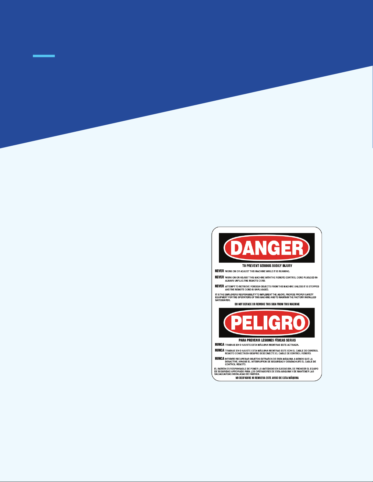
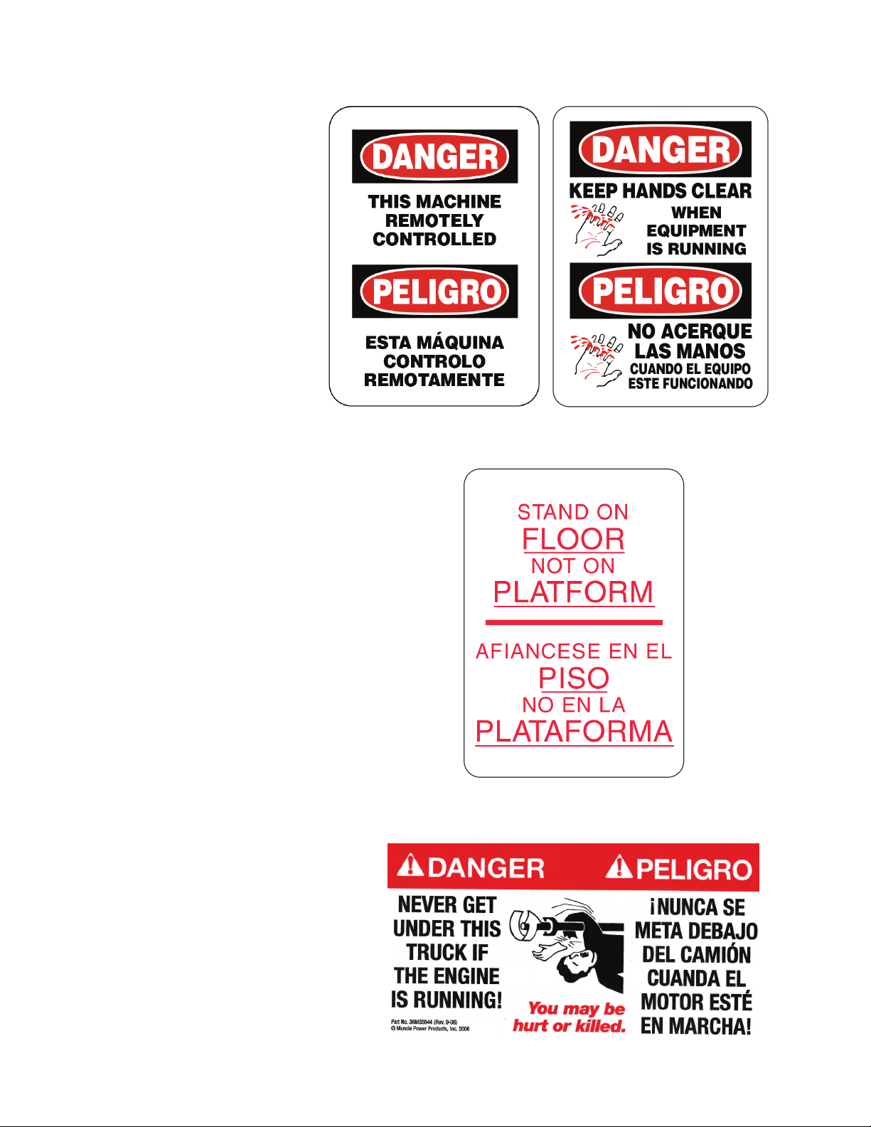
Several safety features have been added to the Volu-Matic 500 machine to ensure operator safety. Study the safety
section thoroughly so that all the features concerning safety are understood. Keep all these features functional so that
no problems will be experienced during machine operation.

8
Safety
The Volu-Matic 500 insulation blowing machine has
full guarding and electrical disconnects for your safety.
Every Volu-Matic 500 machine has this warning displayed
in a prominent place. Do not remove, modify, or deface
the warning label!
WARNING: if any foreign object should enter the
machine; push an emergency stop button in (o), turn
o the master switch, unplug the remote control cord,
and shut the engine or power source down before
retrieving the object. Never reach into the machine
while it is operating.

9
Other wrning signs, cution signs,
nd dnger signs re displyed so
tht the opertor is wre of other
hzrds ssocited with the use
of the mchine. You will see the
following wrnings on the mchine.
Do not remove, modify, or defce
the wrning lbels!
The purpose of this sign is to make the operator
aware that they may lose balance and fall.
This warning sign is displayed on the truck
after installation of a PTO driven machine.
Decals included in the PTO box should be
displayed on the truck as indicated by the
instructions provided by the manufacturer.
Use the installation instructions if you
install the machine.

10
All Volu-Matic 500 machines are factory equipped with side, front, and rear guards. The top of the machine
does not require guarding when correctly mounted in the contractor’s truck as shown in the installation
instructions. If the machine is installed so that the top is exposed, such as in a manufacturing plant, or in an
open top trailer installation, a top guard will have to be equipped.
The front swing gate guards are equipped with a recessed T-Handle Latch 1. These guards must never be
opened while your Volu-Matic 500 machine is in operation – there are shafts with guarding over them, which
are still rotating. If these gates are opened, safety switches 2are mounted to the swing gates which will only
stop chain driven mechanisms and the blower. If the mechanisms do not shut o or stop when either of the
gates are opened, you should request that maintenance be performed on the safety interlocks. You will have
to push the reset button 3in order to restart the machine after the swing gates are closed for machine ready
on. If the safety switch or guard should become damaged, replace them, to ensure safety while operating your
Volu-Matic 500 machine.
1
2
B 6 4 3
5
A

11
The main drive belt guard is placed to ensure safety when starting or stopping the engine and also for
general maintenance that may require the engine to be running while the machine is o. The main drive belt
guard on PTO models is to ensure safety when the machine is o, but the PTO is still engaged on the truck.
There are two emergency stop buttons A& Bthat will completely shut the machine down. Either red
button will stop all machine mechanisms when pushed in (o) overriding all other controls. If the
mechanisms do not shut o or stop when either button is pushed, request that maintenance be performed
on the safety interlocks. The emergency stop buttons must be pulled out (on) for normal operation.
Knowledge of the location and function of these emergency stops is emphasized.
These buttons should be used for any of the following type of emergencies:
– unauthorized individual getting too close to the machine.
– objects falling into machine.
– a machine component breaks.
– a material hose becomes disconnected.
– anything requiring immediate stopping of the machine.
You will have to push the reset button 3in order to restart the machine after the emergency stop buttons
are pulled back out (on) for machine operation. If any safety switch interlock should become damaged,
replace it; keep your Volu-Matic 500 machine safe.
During machine operation, always turn o the “rocker type” master switch 4(light indicates switch is on),
and unplug the remote cord from the receptacle 5before removing any guards for any reason! The material
conditioning slide gate is adjustable from outside the machine using adjustment handle 6.
During machine operation, always stand on the floor to deposit material into the hopper. Under no
circumstances should your hand, arm, stick, or broom be used to move or force feed material down into the
hopper. The Volu-Matic 500 machine is a self-feeding design requiring no outside assistance for smooth flow.
Operators should wear hearing protection if the machine noise makes them uncomfortable or noise level
exceeds permissible exposure limits. CTMW recommends that the operator wear an “approved” dust mask
or respirator for their protection. Safety features are incorporated into the Volu-Matic 500 machine to
protect everyone from serious injury. Operate your machine according to the outlined instructions in this
manual with all safety features in place and working properly. Operating the machine in an unsafe manner
can result in serious injury.

12
Operation
OPERATION MATERIAL HOSE DIAMETER HOSE LENGTH HOSE TYPE
Open Blow
Cellulose
Fiberglass
Rockwool
3-1/2" Minimum 150' Minimum Mark II
Side Wall
Cellulose
Fiberglass
Rockwool
2-1/2" Minimum
3" Minimum
3" Minimum
150' Minimum Mark II
Vacuuming
Cellulose
Fiberglass
Rockwool
4" Only 150' Minimum
200' Minimum Mark II
GENERAL
Use ‘Preliminary checks’ and ‘Initial start-up’ procedures as a check list on your Volu-Matic 500 machine each day
before proceeding to the job site. At the job site, connect hose paying particular attention to recommended hose
size, type, and length as specified in the following table. All hose couplings must be thin wall, 1/16 inch maximum,
to minimize restrictions. Hose purchased from CertainTeed Machine Works is supplied with thin wall couplers and
clamps. The airlock feeder outlet 20 is 4 inches in diameter. A thin wall 4" to 3-1/2" reducer is supplied with new
delivered machines for open blow operations. A thin wall 3-1/2" to 3” reducer is supplied for fiberglass and
rockwool sidewall spray operations and a thin wall 3" to 2-1/2" reducer is supplied for cellulose sidewall spray
operations. Make sure to reduce gradually when using 3" or 2-1/2" hose for spraying.
The Volu-Matic 500 machine will not perform to specifications when held back by undersized and restrictive hoses,
couplings, and nozzles that are used for sidewall spray operations. For sidewall spray operations, make sure the nozzle
that you use has an opening that is a least the same square inch area or greater than the hose selected. The nozzle
should also have a body wall that is not greater than 1/16 - 1/8 inch in thickness and with a smooth tapered entrance.

13
PRELIMINARY CHECKS
1. If your machine was shipped, remove all crating from machine frame. The skids should be removed when the
machine is located in the contractor’s truck or other form of transportation.
2. Be sure that the hopper area is free of loose objects.
3. Check that chain and belt drives are clear of loose
objects and that the drives are adequately tensioned.
4. Check for components that may have vibrated loose, such as;
airstream connections, wiring connections, bearings, guards, etc.
5. Check the oil levels in the blower 10 , right angle gearboxes 11 , and the transmission 12 . When checking the oil
in the blower, turn the brass valve 13 90 degrees to check, a small amount should appear indicating sucient
oil. Refer to the maintenance section for capacities and type of oil to use for each component.
6. Open the material conditioning slide 14 to the number 18 position, fully open. See the operation section
under slide gate control.
7. Make sure that the air bleed control valve 15 is fully closed. The pointer should face the closed label.
See operation section under air bleed system.
8. Make sure the master switch 4is o and that the remote cord is not plugged into the receptacle 5.
9. Close and secure any open guards
PARTIAL VIEW OF
HOPPER AREA
11
12
15
10
10
13
IN THIS PICTURE, THE VALVE IS AT THE
OPEN POSITION. ALWAYS START AT THE
CLOSED POSITION

14
12
17
9
18
19
INITIAL START-UP
1. Make sure the transmission 12 is in the neutral position, see operation
section under four speed transmission. New delivered machines are
shipped with the transmission in neutral. Make sure the front swing
gate guards are closed.
2. Make sure the vacuum exit transition 9is connected to the vacuum
housing exit transition 17 and is firmly connected with rubber hose
and clamps to the material deceleration box.
3. Make sure that the water pump 16 suction and discharge are not
blocked to prevent damage. You can run a diaphragm pump without
water at the suction without causing damage as long as the suction
and discharge are not blocked.
4. Plug a 120 volt light into the generator 18 receptacle. Make sure
that the light is accessible at the outside of the machine frame and
in good working condition.
5. Start the truck and engage the PTO at a low idle in accordance with
the truck manufacturer’s literature. Check that the belt drive from under
the truck is tracking true on the idlers and that no excessive belt slap is
occurring. Shut the truck down for any belt tensioning adjustment. Once
the belts are tensioned properly, bring the truck up to the manufacturer’s
recommended speed established during installation. Always engage the
PTO at a low idle and disengage at a low idle.
6. Once the machine (machine or PTO) is up to speed, the input/clutch
shaft and water pump at the front of the machine will be turning.
The rear gearbox and generator will be turning. The vacuum will not
come on until the electro- magnetic clutch 19 is switched on.
Do not switch the vacuum on while the PTO is engaged.
(see step 12 for proper procedure)
7. Turn on the master switch 4, light indicates that the switch is on.
8. Pull emergency stop buttons A& B out (on) and make sure
both swing gates are closed. Press the reset button 3located
on the front panel.
9. Plug the remote cord shipped with new delivered machines into
the receptacle 5making sure the toggle switch is in the center (o)
position. This is a twist lock connection to prevent the cord from
being pulled out during machine operation.

15
10. Clear the area in front of the airlock feeder outlet 20 for testing.
11. Cycle the toggle switch in the remote cord housing toward the cord
and the blower only will come on, check that rotation is the same as
the arrow Indicates on the blower 10 . With the blower operating
satisfactorily, cycle the switch toward the end of the housing and the
blower and machine mechanisms will operate simultaneously. Check
that rotation is the same as the arrow indicates on the gearboxes 11 .
The tachometer 21 on the machine front panel should read 1050 rpm.
The tachometer also has an hour meter that records machine mechanism
time; airlock feeder, shredder, and hopper components.
12. If all rotations are correct, shut the machine down and engage the
transmission into gear. Start the machine and cycle the remote toggle
switch toward the end of the housing and check that the airlock feeder,
shredder, and hopper components are rotating. For any rotation
problems, check the troubleshooting section or call CTMW.
Warning: Whenever the vacuum is needed, always turn on the toggle
switch 22 before the PTO is engaged. This will prevent premature wear on
the clutch armature. The vacuum can be turned o at any time but, if it is
turned o before the job is complete, disengage the PTO before you turn
the vacuum back on.
13. Bring the truck down to a low idle and disengage the PTO. Flip the toggle
switch 22 to the on position for power to the vacuum clutch. Engage the
PTO and bring the truck idle up to the proper rpm and notice that the
vacuum speeds up. Always switch the vacuum on and then engage the PTO.
This procedure will prevent premature wear on the clutch providing long life.
14. Turn on the light plugged into the generator to check that power is supplied.
15. With everything operating satisfactorily, take some time to get to know
your Volu-Matic 500 machine. Engage and disengage the remote cord
noticing the drives start and stop. With the chain drives on, open and close
the front swing gate guards noticing the drives stop and start.
16. Upon completion of the initial start-up procedures; turn the remote cord
toggle switch o and unplug from the receptacle, turn o the master switch,
turn o any power connected to the generator, idle the truck to a low rpm,
turn o the vacuum by depressing the switch to the o position, and then
disengage the PTO. The Volu-Matic 500 machine is now ready for service.
17. For any problems encountered during machine start-up,
check the troubleshooting section or call CTMW.
20
10
11
21
22

16
23
24 25
PTO CONTROLS
Always engage the PTO at a low idle before increasing engine speed to the truck manufacturer’s
recommended range. Use the truck mounted cruise control and lock to set the PTO speed on the truck
mounted tachometer. Always decrease the idle speed before disengaging the PTO. Make sure that the panel
mounted tachometer 21 on the machine runs at 1050 rpm. CTMW marks and documents the truck idle
speed at installation so that the operator knows where to set the truck mounted throttle.
WARNING: always operate your machine with the truck sitting on a level surface. Operating the machine
when the truck is not level will lead to failure of some machine components. The oil level in the blower,
transmission, and gearbox, may not lubricate internal parts properly when the truck is sitting on an incline.
OPEN BLOW
During open blow operation, you will need the
hopper extension sides 23 in order to fully utilize
the expanded hopper area. The extension back
24 connects to the sides. Place the sides over
the weld studs on the machine top frame and bolt
to the extension back. Use the wing nuts supplied
with NEW delivered machines to hold in place.
SIDEWALL
During sidewall spray operation, you will need
to mount the 4 inch hose to the vacuum inlet.
The vacuum housing transition exit 17 will be
connected to the 6 inch elbow tube that will
route all the recovery of excess sprayed fibers
to the material deceleration box 25 .
HOSE
Connect hose for open blow or sidewall operations
with supplied reducers to the feeder outlet 20 .
Make sure to use recommended hose size and type
as specified in the table. Connect hose for vacuuming
to the front cover 7by lifting the door 8 . If your
truck is not set up with double doors as illustrated
in the installation instructions, you will have to make
provisions for connecting the hose. In the following
drawing, a through-the-wall sleeve connection is shown.
Never connect the hose to the feeder outlet or vacuum
inlet cone creating a short radius bend in the hose, this
will result in excessive hose wear. A short radius bend
in the hose can also result in poor coverage, excessive airlock feeder wear, and/or plugged hoses for open blow
or sidewall operation. Additionally, high feed rates for open blow may require a 25' to 50' length of 4" diameter
hose at the outlet connection if excessive high air pressure is experienced when using all 3-1/2" diameter hose.
25
17
7
8

17
26
WARNING: Recommended hose size, type, and length must be used to achieve maximum results.
CTMW cannot guarantee performance of the Volu-Matic 500 machine if hoses are undersized or
worn or damaged or hoses other than those recommended are used.
Repeated warnings about choice of hose may seem to be an attempt
to sell our brands, but we must stress the importance of proper hose
selection for the type material and operation. A rough bore corrugated
hose is necessary for blown fibers since smooth bore rubber or plastic
will roll shredded material into small tight balls. Your Volu-Matic 500
machine has been engineered, when properly adjusted, to condition
fibers for optimum coverage. Improper hose selection will degrade
fibers conditioned by the machine and reduce insulation value in
blown material. Do not deviate from hose diameters, types, or length
as specified in the table.
LOADING
The operator loads the machine hopper from a standing
position on the floor depositing bags of material on the drop
gate 26 . Pull the drop gate sharply toward you to lay down
for loading and then deposit the material into the hopper.
Do not build scaolding or use a foot stool to load material
into the Volu-Matic 500 machine. This moves the operator
closer to the rotating components in the hopper and
provides a way to lose balance and fall.
Load three to four bags of material into the hopper being
particularly careful not to leave pieces of bag in the material
since this will clog and stall the machine. Make sure to keep
the hopper full during operation but do not overload
preventing material from overflowing onto the truck floor.
WARNING: DO NOT attempt to remove any foreign object from the machine until it is completely shut
down; master switch turned o, remote cord unplugged, and the PTO disengaged. Failure to do so will
result in serious injuries by the rotating components in the hopper.
THIS
NOT
THIS

18
VOLU-MATIC™ 500 RECOMMENDED START SETTINGS
NOTE 1: Use these settings as a starting guide only. Variations between materials of the same type and
variations between batches from the same manufacturer may require dierent settings than those suggested.
Remember, the material manufacturer’s instructions prevail since they guarantee the final results.
NOTE 2: Air pressure settings for sidewall operation are for dense pack, net fill, and drill & fill of outside
walls in older structures. Spraying sidewalls will result in higher pressure based on water in the air stream.
NOTE 3: Filling of tee post and corners will require that the machine be slowed down considerably to use
the 2" to 1" tapered nozzle.
GENERAL INSTRUCTIONS:
1. Set the machine speed so that the panel mounted tachometer reading is no less than 1050 and no more than
1100 rpm for open blow operation. Reduce machine speed until tachometer reading is 800 - 850 for all
sidewall operations but spraying, reducing speed for spraying sidewalls will result in loss of vacuum pressure.
NOTE: Remove belts from generator when reducing speed for sidewall operations.
2. Vary the air bleed pressure first. If you cannot get the desired results by opening or closing the air control
lever, then...
3. Vary the slide gate next. If you cannot get the desired results by closing or opening the slide gate, then...
4. Go to the next highest or lowest speed on the transmission. If you cannot get the desired results changing
the speed, then...
5. Remove stator bar. If you cannot get the desired results by removing the stator bar, then start with varying
the air pressure again.
OPERATION MATERIAL SLIDE GATE
SETTING
TRANSMISSION
GEAR
AIR BLEED
PRESSURE
Open Blow
Cellulose
Fiberglass
Rockwool
16"
16"
12"
3rd
3rd
2nd
2.0 – 3.5 psi
2.0 – 3.5 psi
4.5 – 5.5 psi
Side Wall
Cellulose
Fiberglass
Rockwool
8"
1st
2nd
1st
1.0 – 1.25 psi
1.0 – 1.25 psi
1.5 – 1.75 psi

19
MATERIAL SLIDE GATE
Refer to the chart and select the proper setting for material and
type of operation. Rotate the handle 6on the machine front panel
clockwise to open the material slide gate 14 . Line up the edge of
the slide gate (see arrow) with desired setting on the scale 27 .
The scale is calibrated in inches of opening.
FOUR SPEED TRANSMISSION
Refer to the chart and select an appropriate gear for material and
type of operation. Shift the lever 28 into gear in accordance with
decal instructions on the machine front panel. Since the transmission
is not synchronous, it may be necessary to pull the gears through by
hand using the pulley 29 so that the gears mesh allowing you to
change them. This should never be attempted or gears shifted
while the machine is operating.
WARNING: NEVER attempt to change gears while the Volu-Matic 500
machine is in operation. Always change gears when the machine is
completely shut down. Failure to do so can result in serious personal
injuries or a severely damaged.
AIR VOLUME CONTROL SYSTEM
Refer to the chart for correct air bleed pressure for material and type
of operation. Air flow rate may be controlled with the air bleed control
valve 15 while monitoring system pressure on the air gauge 30 .
The system back pressure must be set under load with your
Volu-Matic 500 machine operating with full length and proper size
hose while material is being blown. Always start the adjustment with
the air bleed control valve in the fully closed position. If the air flow
and pressure deliver the desired results with the valve closed, then
do nothing to the valve. As you begin to open the valve, air is bleed
o from the exit of the blower preventing flow of all air to the airlock
feeder. As you open the valve, be careful to not open completely during
open blow or the blowing hose could clog because of not enough air.
27
14
29
28
30
15

20
VACUUM SYSTEM
The high speed centrifugal vacuum 31 is designed to use 4" hose
only. The vacuum is belt driven through an electro-magnetic clutch
19 so that the vacuum can be o during open blow operations.
Make sure that the material deceleration box and exit transitions are
mounted. Use the following steps for starting the vacuum system.
1. With PTO disengaged, turn on the master switch 4and then
the vacuum clutch switch 22 .
2. Connect vacuum hose and spray hose when ready to start job.
3. Engage the truck mounted PTO box at a low idle.
4. Idle the truck up to the correct range established
during installation.
VACUUM CLUTCH WARNING: Upon completion of the sidewall
spray operation, the vacuum can be switched o while the
PTO is still engaged. Make sure that the job is complete.
Any engagement of the clutch while the PTO is engaged will
result in premature wear of the armature in the clutch assembly.
Additionally, the vacuum switch is wired through the master
switch so that the vacuum switch would not be left on accidentally.
This could drain the truck battery down overnight causing the
clutch to slip or not function at all.
GENERATOR
The generator 18 supplies 120 volt power on the machine
whenever the truck mounted PTO box is engaged and rpm
is increased to programmed speed. Refer to manufacturer’s
literature for any information concerning use of the generator.
WARNING: Always make sure that any device (stud scrubber,
light, etc.) Plugged into the generator is o when the truck
PTO controls are engaged or disengaged. This will prevent low
voltage output which could damage the generator.
WATER PUMP
The water pump 16 supplies water on the machine whenever
the truck mounted PTO box is engaged. Refer to manufacturer’s
literature for plumbing to a water source. During winter operations,
the pump foot 33 will slide out of the pump mount 34 . Roll o
the link belts and remove all water line connections and store
inside until the next time the pump is needed.
31
22
19
18
34
33
16
Table of contents
Popular Blower manuals by other brands

XPower
XPower X-600 owner's manual

Ebmpapst
Ebmpapst R2E210-AB34-05 operating instructions

Yard Works
Yard Works 60-3869-2 owner's manual

Z.I.P.P.ER MASCHINEN
Z.I.P.P.ER MASCHINEN ZI-LBR40V-AKKU user manual

IKRAmogatec
IKRAmogatec Gartenmeister GM ALB 40 operating instructions

FLORABEST
FLORABEST FKM 2400 A1 operating instructions