3.4 RS485 interface of inverter
Figure 3.4 RS485 pin
Transmission RS485
differential signal
Table 3.1 RS485 pin port definition
4.Fault and troubleshooting
connected
according to
the wiring
diagram of
the meter
Check if the actual
connection is the same
as the requirement of
the wiring diagram.
Pay special attention to
“N” position of the
voltage, the high & low
end of the current and
terminal labeling are
different from actual
number.
While
checking the
connection, be
sure the meter
is in the state
of
disconnection,
guarantee the
safety of
human life.
The
communicati
on setting
information
of the meter
may be
incorrect
Check if the
communication setting
information such as
communication
address, baud rate,
verification mode is the
same as the PC
settings.
5.Displayed functions
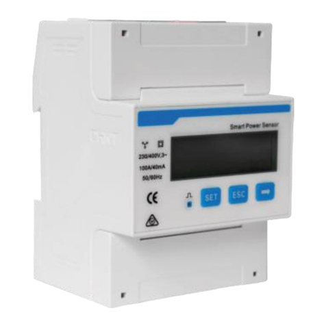
When the energy meter is in normal working condition (on load
state), the positive pulse indicator should be flashed. If long time for
no flashing or light for the indicator, please check whether the wiring
mode of the energy meter is right or not.
Table 5.1 LCD logo meanings
The unit of the voltage, the display data of indicating
LCD is voltage
The unit of the current, the display data of indicating
The unit of the active power, the display data of
indicating LCD is active power
The unit of the reactive power, the display data of
indicating LCD is reactive power
The unit of the frequency, the display data of
indicating LCD is frequency
The unit of the active energy, the display data of
indicating LCD is active energy
6.Export limitation function setting
The steps for matching R5 series inverters are as follows:
(1)Download eSolar O&M APP
Web to eSolar website https://fop.saj-electric.com to scan the QR
code and download “eSolar O&M” APP (or download it from
Google Play or App Store by searching “eSolar O&M”). After the
installation on your phone, please login it with your installer account.
(2)Log in APP→ Click “My” → Click “Remote control” → Click
“WiFi” /“Bluetooth”→ Click “Next step”. as shown in Figure6.1.
Please refer to WiFi/GPRS/4G module manual for detailed
connection operation.
(3)Enter “local connect” page and select “Export limitation setting”
→ input password:201561 as shown in Figure6.2.
Figure 6.1 Local connect Figure 6.2 Export limitation setting
(4)Turn on “export limitation”, Wait for 15s countdown seconds to
set successfully,supply the power mode and current mode,as shown
in Figure6.3 and Figure6.4
Figure6.3 Countdown interface Figure6.4 Power limit/Current limit setting
Note:
1.Power mode and current mode could be alternatively selected;
2.The setting parameter cannot exceed the given range value
3.When the setting is completed, the export limitation system will
begin to run.


