Saker HVCP Series User manual

Fiber Optic Isolated Current Probe. HVCP
FEATURES
▪︎ Rogowsky coil with 2MHz bandwidth AC measurements
▪︎ Selectable optic cable length
▪︎ 500A, 1000A, 2000A models, optional customisation
▪︎ Auto zero, auto test and optical link auto calibration features
▪︎ Fiber optic link for increased EMI rejection and high voltage isolation
▪︎ High common mode rejection
▪︎ Low noise
▪︎ No 50/60Hz low frequency noise
▪︎ Battery powered, connects to any oscilloscope
▪︎ Remote standby mode for low power consumption
▪︎ Low Battery visual indication
▪︎ Patented design
BR-HVCP-1119-rev2
Specifications subject to change without notice
www.saker-mv.com

DESCRIPTION
The HVCP is a novel AC current probe that provides high voltage isolation via fiber optic
cables. Not only is this approach advantageous from the voltage isolation point of view, but
is also immune to typical radiated interferences and capacitances created when using long
coaxial measuring cables. The current sensor is a rogowski coil which is small, lightweight
and can be tied around conductors without breaking the current path. Both probe head and
handheld receiver are battery powered. The receiver lacks a proprietary output connector
and thus can be connected to any oscilloscope or measuring instrument via a standard BNC
connector.
A calibration feature starts a software routine that self-tests both units, zeroes the output and
adjusts the fiber optic link to minimize measurement errors due to temperature drifts or
offsets. The probe lacks the typical 50/60Hz noise seen in many Rogowski current probes.
When not in use both emitter and receiver can be configured into standby mode, which
reduces power consumption and increases battery duration. The receiver also signals the user
of a possible low battery condition in both probe head or receiver.
SPECIFICATIONS
HVCP Specification
Units
Bandwidth, rise time derived
2Hz…2MHz
Maximum measurable current
2000 (HVCP2000)
1000 (HVCP1000)
500 (HVCP500)
A
Overall accuracy
%
Receiver output connector
BNC
Receiver output range
V
Output ratio
2.5 (HVCP2000)
5 (HVCP1000)
10 (HVCP500)
mV/A
Measuring instrument minimum input
impedance
200
Calibration time
3
s
5
±
k
Ω
2
±
BR-HVCP-1119-rev2
Specifications subject to change without notice
www.saker-mv.com

USAGE
Output noise
3
mV rms
Receiver power, normal mode
100
mW
Receiver power, standby mode
20
mW
Probe head power, normal mode
380
mW
Probe head power, standby mode
20
mW
Probe head batteries
2x1.5V AAA type
Receiver batteries
2x1.5V AA type
Rogowski enclosed circular conductor
diameter, max
71
mm
Rogowski enclosed planar busbar
dimensions, max
100x10
mm
Working temperature
-20…+60
ºC
Max. operating humidity, non-dondensing
85
%
Fiber optic bundle length
3m standard, others optional
m
Dimensions
See dimensions section
Normative references
EMC IEC 61326-1:2012, ESD
61000-4-2 (A), RFI 61000-4-3 (A)
Safety IEC 61010-1, 61010-2-030,
RoHS 2011/65/EU
BR-HVCP-1119-rev2
Specifications subject to change without notice
www.saker-mv.com

TURNING ON
To turn on either the probe head or the receiver, press the TURN ON button until the ON Led
lights. It takes a short press to turn on the units. If the unit fails to turn on check if the
batteries are dead, and replace them.
The probe head cannot be turned on remotely.
TURNING OFF
The probe head can be turned off in two ways. Either directly by pressing the TURN ON
button for 1 second or remotely by turning off the receiver while the fiber optic cables are
connected to the probe head. In either case the ON led will turn off.
To turn off the receiver press the TURN ON button for 1 second. The ON led light will turn
off. As mentioned, if the fiber optic cables are connected to the probe head, it will also turn
off automatically.
BR-HVCP-1119-rev2
Specifications subject to change without notice
www.saker-mv.com

STANDBY MODE
This mode will place both the probe head and receiver (if the fiber cables are connected
between them) in a low power mode for extended battery duration. It is recommended to use
this feature every time the probe is not in use, even for shorts periods of time. Since the probe
head can be set into low power mode remotely from the receiver, potentially dangerous
situations where the measured system is floating at high voltage, are avoided.
To enter standby mode, press the TURN ON button shortly in either unit. The ON green led
will start blinking. If the fiber cables are connected, the other unit will also enter low power
mode.
To return to normal mode press the TURN ON button shortly in either unit. If both units are
connected by the fiber cables, both units will resume normal operation automatically. After
normal operation is resumed the ON led will light continuously.
FIBER OPTIC CONNECTIONS
The probe head unit and the receiver are connected with 2 fiber optic cables supplied in a
bundle. Both cables are differentiated by colored strip markers, yellow and red. Each
connector uses a bayonet type connector that requires a small twist for it to be properly fixed
in the unit.
BR-HVCP-1119-rev2
Specifications subject to change without notice
www.saker-mv.com
WHEN NOT IN USE ALWAYS PROTECT THE OPTICAL CONNECTORS FROM DUST
WITH THE SUPPLIED PROTECTIVE COVERS

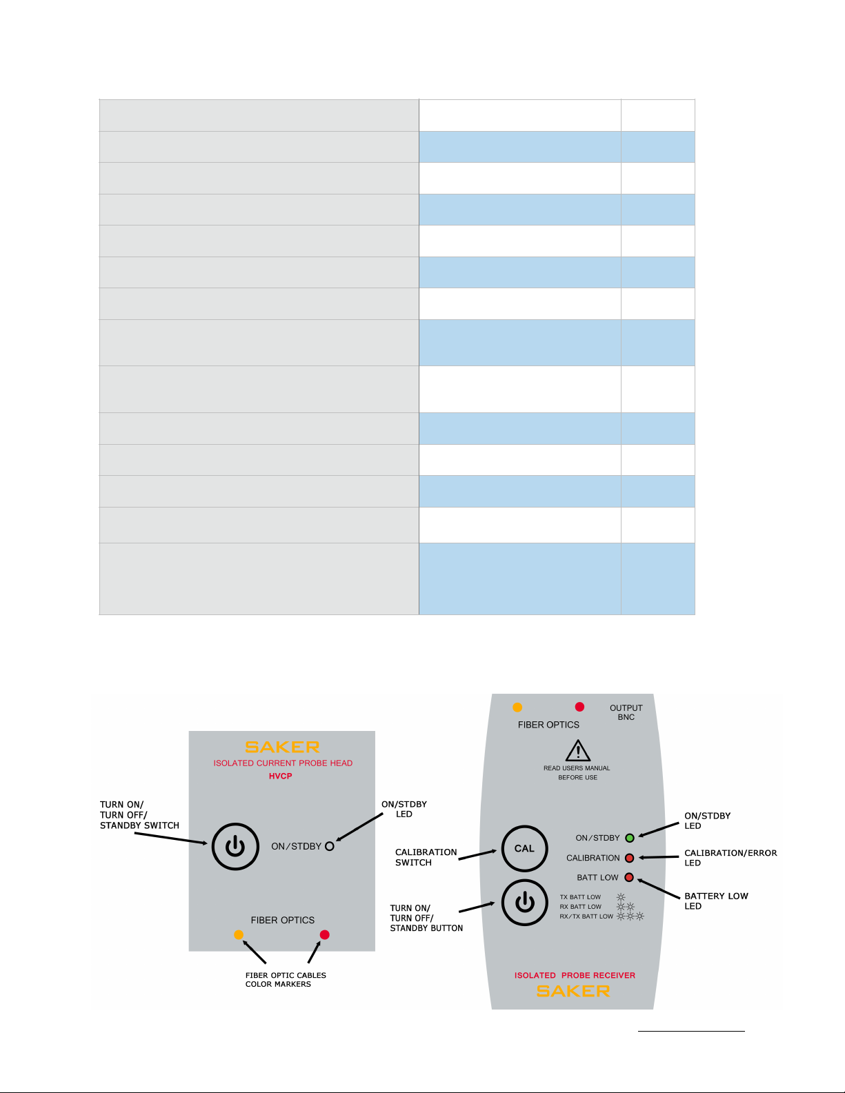
Before operating the unit, connect both cables in their respective connectors following the
correct color code for each side.
CALIBRATION
Calibration is needed to adjust the analog parameters of the
fiber optic link and correct for offsets and temperature drifts in
each unit. Every time the CAL button is pressed both probe head
and receiver run self-test prior to calibration. It is not necessary
to remove the probe from the measured system in order to
execute the calibration. Prior to calibration connect both fiber
optics ensuring the correct color codes are positioned in each
side.
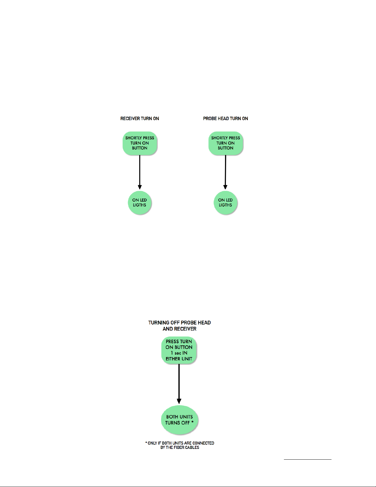
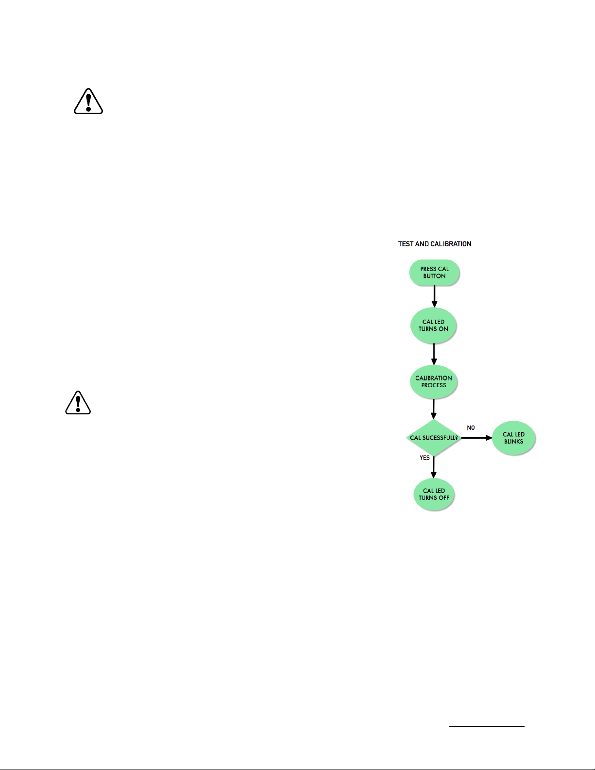
A short blink from the CAL led indicates that calibration is
required. To execute calibration, first turn on both units and then
shortly press the CAL button. The CAL led will turn on. If the
cables are not connected, or for some reason both units cannot
communicate, the CAL led will blink signaling an error. The
calibration process will take a couple of seconds. If the
procedure completed successfully the CAL led will turn off, otherwise it will blink and remain
in that state. In this case, check the cable connections or the batteries in both units.
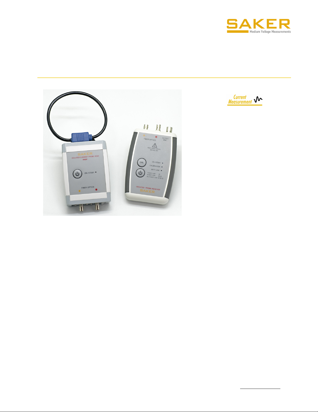
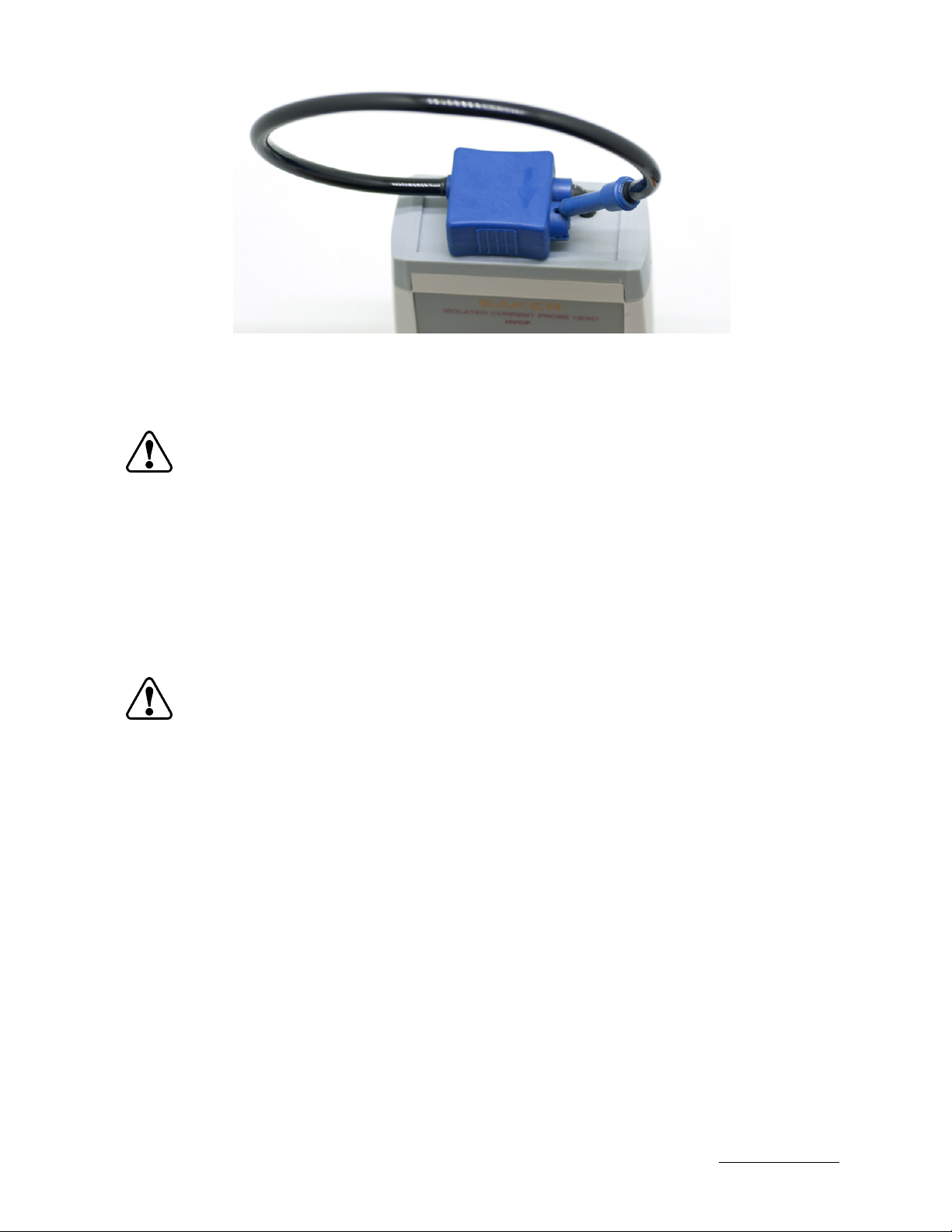
PLACING THE PROBE HEAD
The probe head uses a rogowski coil as its measuring element. The conductor to be measured
must be placed inside the coil. Open the coil by pulling its retention and embrace the busbar
or cable to be measured.
BR-HVCP-1119-rev2
Specifications subject to change without notice
www.saker-mv.com
DO NOT TWIST OR BEND THE FIBER OPTIC CABLE AT SHARP ANGLES. MINIMUM
BENDING RADIUS IS 6 CM
CALIBRATION SHOULD BE PERFORMED AT LEAST
ONCE AFTER TURNING ON
ON THE EQUIPMENT

The coil head has an arrow at the top that indicates the positive sign of the passing current.
Currents that flow in the opposite sign will measure as negative voltages in the HVCP
receiver.
WARNING REGARDING ISOLATION
Due to their non-conductive nature, the fiber optic cables provide excellent isolation between
probe head and receiver. However the probe head can and should be considered floating at
the same potential of the measured conductor. Thus the whole body of the HVCP probe head
including the metallic bayonet connectors can be at hazardous potentials.
It is advisable to install a voltage detector/indicator on the measured line that provides visual
and clear indication about the presence of potentially dangerous voltages. SAKER offers the
MVD and MVDH series of medium voltage presence detectors.
RECEIVER-OSCILLOSCOPE CONNECTION
A BNC-BNC cable is supplied to connect the receiver to a measuring oscilloscope. Use of a
good quality cable is recommended as it could affect the measurement.
BR-HVCP-1119-rev2
Specifications subject to change without notice
www.saker-mv.com
Arrow on top of coil sensor, indicates positive current
direction
THE HVCP PROBE HEAD IS NOT A HANDHELD INSTRUMENT AND SHOULD BE
CONSIDERED TO BE FLOATING AT THE SAME POTENTIAL OF THE CURRENT
CARRYING CONDUCTOR
MAKE SURE NO DANGEROUS VOLTAGE POTENTIALS ARE PRESENT WHILE
INSTALLING THE PROBE HEAD IN THE MEASURED SYSTEM

Set the oscilloscope vertical scale at an appropriate scale given the conversion ratio of the
HVCP model (see specifications section) in question.
LOW BATTERY CONDITION
Both the receiver and the probe head will measure the voltage of the batteries to warn the
user in case of a low battery condition. The signalling threshold has been adjusted for typical
alkaline AA batteries. A single red led is used at the receiver to display all 3 possible “low
battery” cases.
In case of a battery low event the BATT LOW led will quickly blink a number of times followed
by a 4 second pause in the following way:
-One blink: the batteries at the HVCP probe head should be
replaced
-Two blinks: the batteries at the HVCP receiver should be replaced
-Three blinks: the batteries at the HVCP receiver and remote probe
should be replaced
BATTERY REPLACEMENT
Both units use standard 1.5V AA batteries. To replace the batteries open the back cover of
the respective unit. The HVCP10 probe head requires the use of a small phillips head
screwdriver to open the back cover. Follow the polarity sign to replace the batteries and
close the cover afterwards.
ORDERING CODES
CODE
Description
HVCP2000
HVCP current probe, 2MHz, 2000A range, including:
Head and handheld receiver unit
3 meter fiber optic bundle cables
1m BNC to BNC cable
4xAA batteries
Carrying case
CODE
BR-HVCP-1119-rev2
Specifications subject to change without notice
www.saker-mv.com
REMOVE THE BATTERIES FROM INSIDE THE EQUIPMENT IF IT IS TO BE
STORED DURING MORE THAN 5 MONTHS

CUSTOMIZATION
SAKER offers customization services for this product. Typically a end user may need a
different current measuring range, a special increased fiber optic cable length between probe
head and handheld receiver unit or a higher capacity battery pack to power the remote
probe head for long term measurements.
HVCP500
HVCP current probe, 2MHz, 500A range, including:
Head and handheld receiver unit
3 meter fiber optic cables
1m BNC to BNC cable
4xAA batteries
Carrying case
HVCP1000
HVCP current probe, 2MHz, 1000A range including:
Head and handheld receiver unit
3 meter fiber optic cables
1m BNC to BNC cable
4xAA batteries
Carrying case
HVCP2000L
HVCP current probe, 100kHz, 2000A range, including:
Head and handheld receiver unit
3 meter fiber optic bundle cables
1m BNC to BNC cable
4xAA batteries
Carrying case
HVCP500L
HVCP current probe, 100kHz, 500A range, including:
Head and handheld receiver unit
3 meter fiber optic cables
1m BNC to BNC cable
4xAA batteries
Carrying case
HVCP1000L
HVCP current probe, 100kHz, 1000A range including:
Head and handheld receiver unit
3 meter fiber optic cables
1m BNC to BNC cable
4xAA batteries
Carrying case
HVCPFO-L
Fiber optic bundle for HVCP, substitute -L for the length in meters:
-7 : 7 meter cable
-15: 15 meter cable
For lengths other than 3, 7 or 15m contact us.
Description
CODE
BR-HVCP-1119-rev2
Specifications subject to change without notice
www.saker-mv.com
This manual suits for next models
3
Table of contents
Popular Accessories manuals by other brands

Cater-Cool
Cater-Cool CK5085 Installation use and service manual

Scent Works
Scent Works JOLLY SNOWMAN Important instructions

Paradox
Paradox NV780MR installation manual

Silvercrest
Silvercrest STK 17 A1 Assembly, operating and safety instructions

Metalcraft
Metalcraft GR-4100 Mounting and user instructions

Silvercrest
Silvercrest 91089 Operation and safety notes