Sakura SXAO-110HAS Manual

All in one Air to Water Heat Pump
Split system
Installation and Service Manual
Models: SXAO-110HAS SXAO-140HAS
SXAO-160HAS/3
(Please read the manual thoroughly before operation. )

1
CONTENTS U U
INTRODUCTION...................................................……….......………………..2
PARTS AND DESCRIPTIONS……………………………………….…….…….3
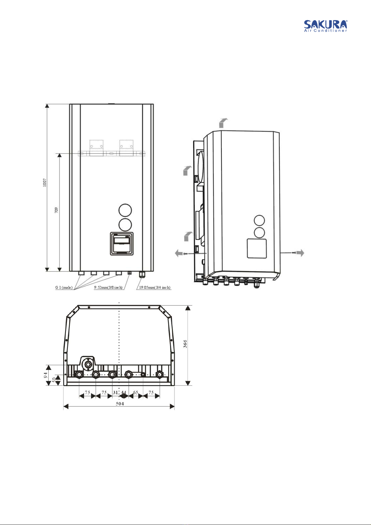
Indoor unit- all models (External)………………………………………………………….….3
Indoor unit- all models (Internal)………………………………………………………….…..4
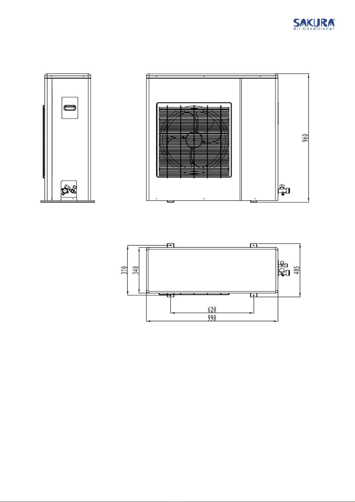
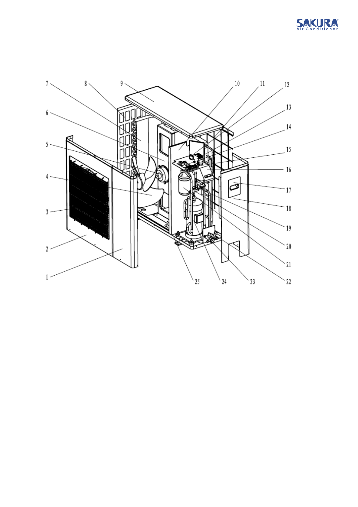
Outdoor unit (External): SXAO-110HAS and SXAO-140HAS………………………...…5
Outdoor unit (External): SXAO-110HAS and SXAO-140HAS………………….…..……7
Outdoor unit (External): SXAO-160HAS/3………………………………………………...8
Outdoor unit (External): SXAO-160HAS/3…………………………………………….…..9
SERVICE SPACE………………………………………………………………....10
OPERATING THE UNIT…………………………………………………….……11
Introduction………………………………………………………………………………….….11
OPERATING THE DIGITAL CONTROLLER…………………………………..11
Features and functions……………………………………………………………………..…12
Base controller functions…………………………………………………………...…..12
Clock function………………………………………………………………………...…12
Schedule timer function………………………………………………………….……..12
Name and function of buttons…………………………………………………………….….13
Name and function of LCD icons………………………………………………………….…15
Setting up the controller……………………………………………………………………....17
Setting the clock and the day of the week……………………………………….…...17
Setting the key lock………………………..……………………………………….…...17
Setting the schedule timer……………………………………………………………...17
Description of the operation modes………………………………………………….…..….18
Space heating operation…………………………………………………….………....18
Space cooling operation………………………………………………………………..18
Domestic water heating operation………………………………………………..……18
Controller operations………………………………………………………………….……….19
Manual operation………………………………………………………………………..19
Schedule timer operation……………………………………………………………….20
Programming and consulting the schedule timer………………………………………..…22
Getting started…………………………………………………………………………..….….22
Programming. …………………………………………………………………………..23
Tips and tricks………………………………………………………………………..….24
WIRING DIAGRAM……………………………………………………………….25
DIGITAL SWITCH AND DETAILED DESCRIPTION…………………….……28
Digital switch introduction ……………………………………………………………………28
DC voltage (0~10V) control …………………………………………………………………29
MAINTENANCE…………………………………………………………………..29
TROUBLESHOOTING……………………………………………………..…….30
DISPOSAL REQUIREMENTS………………………………………………..... 30
READ THESE MANUAL ATTENTILY BEFORE STARTING UP THE UNIT. DO NOT THROW IT
AWAY. KEEP IT IN YOUR FILES FOR FUTURE REFERENCE.
Before operating the unit, make sure the installation has been carried out correctly by a
professional dealer.
If you feel unsure about operation, contact your dealer for advice and information.

2
INTRODUCTION
This manual
This manual describes how to start up and switch off the unit, set parameters and configure the
schedule timer by means of the controller, maintain the unit and solve operational problems.
This unit
All in one split system consists two parts: Indoor unit and Outdoor unit. They are connected via
refrigerant pipes. The indoor unit is the indoor part of the reversible air to water heat pumps. These
units are designed for all mounted indoor installation and used for both heating and cooling
applications. The unit can be combined with fan coil units, floor heating, low temperature radiators,
and the domestic hot water tanks.
The unit range consists of two main versions: a heating/cooling version and a heating only version.
Both versions can optionally be delivered with an integrated backup heater for additional heating
capacity during cold outdoor temperatures. The backup heater also serves as a backup incase of
malfunctioning of the outdoor unit. The backup heaters are available in different capacities.
Options
Domestic hot water tank option
An optional domestic hot water tank with integrated 3KW electrical booster heater can be connected
to the indoor unit. The domestic hot water tank is available in different sizes.

3
PARTS AND DESCRIPTIONS
Indoor unit- all models (External)

4
Indoor unit- all models (Internal)
1. Air purge valve
Remaining air in the water circuit will be
automatically removed via the air purge valve.
2. Backup heater vessel
The backup heater heats the water in the
backup heater vessel.
3. Backup heater
The backup heater consists of an electrical
heating element that will provide additional
heating capacity to the water circuit if the
heating capacity of the outdoor unit is
insufficient due to low outdoor temperatures.
4. Pump
The pump circulates the water in the water
circuit.
5. Manometer (water pressure)
The manometer allows readout of the water
pressure in the water circuit.
6. Flow switch
The flow switch checks the flow in the water circuit and protects the heat exchanger against
freezing and the pump against damage.
7. Manometer (refrigerant pressure)
The manometer allows readout of the refrigerant pressure in the refrigerant circuit.
8. Motorized 3-way valve
The motorized 3-way valve is used to change the water circuit between space heating/cooling and
hot water supply.
9. User interface
The user interface allows the installer and user to set up, use and maintain the unit.
10. Switch box

5
The switch box contains the main electronic and electrical parts of the indoor unit.
11. Refrigerant liquid connection
12. Refrigerant gas connection
13. Water outlet connection (hot water)
14. Water inlet connection (hot water)
15. Water outlet connection (space heating/cooling water)
16. Water inlet connection (space heating/cooling water)
17. Water filter
The water filter removes dirt from the water to prevent damage to the pump or blockage of the
evaporator. The water filter must be cleaned on a regular base.
18. Heat exchanger
19. Refrigerant service valve
20. Expansion vessel (10L)
21. Temperature sensors
Four temperature sensors determine the water and refrigerant temperature at various points in the
water circuit.
22. Water circuit service valve
23. Pressure relief valve
The pressure relief valve prevents excessive water pressure in the water circuit by opening at 3
bar and discharging some water.

6
Outdoor unit (External): SXAO-110HAS and SXAO-140HAS

7
Outdoor unit (Internal): SXAO-110HAS and SXAO-140HAS
1. Right front plate 2. Front plate
3. Air outlet grills 4. Outdoor fan
5. Fan motor 6. Fan motor holder
7. Condenser 8. Left plate
9. Top plate 10. Separated plate
11. Back grill 12. Capacitor
13. Contactor 14. Main PCB assembly
15. Terminal 16. Electric box
17. Hand holder 18. Right back plate
19. Thermal expansion valve assembly 20. Four-way valve assembly
21. Refrigerant storage vessel 22. High pressure service valve
23. Low pressure service valve 24. Compressor
25. Base plate

8
Outdoor unit (External): SXAO-160HAS/3

9
Outdoor unit (Internal) - SXAO-160HAS/3
1. Right front plate 2. Hand holder
3. Air outlet grills 4. Front plate
5. Outdoor fan 6. Fan motor
7. Left plate 8. Condenser
9. Fan motor holder 10. Top plate
11. Back grill 12. Separated plate
13. Electric box 14. Main PCB assembly
15. Contactor 16. Four-way valve assembly
17. Capacitor 18. Terminal
19. Refrigerant storage vessel 20. Right back plate
21. Oil separated vessel 22. Compressor
23. Low pressure service valve 24. High pressure service valve
25. Thermal expansion valve assembly 26. Base plate

10
SERVICE SPACE
Below you will find the minimum space required to be able to complete service and maintenance
tasks on the units.
Indoor unit
Outdoor unit

11
OPERATING THE UNIT
INTRODUCTION
The heat pump system is designed to provide you a comfortable indoor climate for many years at low
energy consumption.
To get the most comfort with the lowest energy consumption out of your system, it is very important
to observe the items listed below.
Defining possible schedule timer actions for each day and filling out the form at the very end of this
manual can help you minimize the energy consumption. Ask your installer for support if required.
Make sure the heat pump system works at the lowest possible hot water temperature required to
heat your house.
Next recommendations only apply to installations with an optional domestic hot water tank.
·Make sure the domestic water is only heated up to the domestic hot water temperature you
require.
Start with a low domestic hot water temperature set point (e.g. 45℃), and only increase if you
feel that the domestic hot water supply temperature is not sufficient.
·Make sure both the domestic water heating and booster heating start 1 to 2 hours before you
expect domestic hot water usage.
In case you only need a lot of domestic hot water in the evening or in the morning, only allow
domestic water heating during early morning and early evening. Also keep hours with low
electricity cost tariffs in mind.
OPERATING THE DIGITAL CONTROLLER
Operating the unit comes down to operating the digital controller.
Never let the digital controller get wet. This may cause an electric shock or fire.
Never press the buttons of the digital controller with a hard, pointed object. This may damage
the digital controller.
Never inspect or service the digital controller yourself, ask a qualified service person to do this.

12
Features and functions
The digital controller is a state of the art controller that offers full control over your installation. It can
control a cooling/heating and a heating only installation.
Both installations are available in multiple versions which vary in capacity, electrical supply and
installed equipment (backup heater in the indoor unit or domestic hot water tank with a booster
heater).
NOTE ·Descriptions in this manual that apply to a specific installation or that depend on the
installed equipment, are marked with an asterisk (*)
·Some functions described in this manual may not be available or should not be available.
Ask your installer or your local dealer for more information on permission levels.
Base controller functions
The basic controller functions are:
Turning the unit ON/OFF.
Operation mode change-over:
-Space heating
-Space cooling (*)
-Domestic water heating (*)
Temperature set point adjustment
NOTE (*) The functions “space cooling” and “domestic water heating” can only selected when the
corresponding equipment is installed.
Clock function
The clock functions are:
24 hours real time clock.
Day of the week indicator.
Schedule timer function
The schedule timer function allows the user to schedule the operation of the installation according
to daily or weekly program.

13
Name and function of buttons
1. OPERATION LED
The operating LED is lit during space cooling or space heating operation. The LED blinks in 1Hz frequency if a
malfunction occurs. When the LED is OFF, space cooling or space heating is inactive while the other operation modes
can still be active.
2. COOLING/HEATING ON/OFF BUTTON
The ON/OFF button starts or stops the heating or cooling function of the unit.
NOTE: Remark that pushing the button has no influence on the domestic water heating. Domestic
water heating is only switched on or off by means of the button.
3. TIMER/ PROGRAMMING BUTTON
This is a multi-purpose button. It is used to set timer and program the controller. The function of the button
depends on the actual status of the controller or on previous actions carried out by the operator.
4. HOUR ADJUST BUTTON
This button is used to the hour setting for relating functions.
5. DAY OF THE WEEK ADJUST BUTTON
This button is used to the day of the week setting for relating functions.
6. MINUTE ADJUST BUTTOM
This button is used to the minute setting for relating functions.
7. TIME/TIMER ON ADJUST BUTTON
This multi-purpose button is used to adjust the time, the day of the week and also used in timer on function.

14
8. TIME/TIMER OFF ADJUST BUTTON
This multi-purpose button is used to adjust the time, the day of the week and also used in timer on function.
9. TEMPERATURE ADJUST BUTTON
This multi-purpose button is used to adjust the current set point of the cooling/heating water temperature. Press
this button once, the temperature increases 1℃. Temperature range for cooling: 5℃ to 22℃. Temperature range for
heating: 25℃ to 55℃.
And it is also used to adjust the timer ranges.
10. TEMPERATURE ADJUST BUTTON
This multi-purpose button is used to adjust the current set point of the cooling/heating water temperature. Press
this button once, the temperature decreases 1℃. Temperature range for cooling: 5℃ to 22℃. Temperature range for
heating: 25℃ to 55℃.
And it is also used to adjust the timer ranges.
11. DOMESTC HOT WATER TEMPERATURE ADJUST BUTTONS
This button is used to adjust the current set point of the domestic hot water temperature. Press this button once,
the temperature increases 1℃. Temperature range for hot water: 30℃ to 80℃.
The button is not used when the domestic hot water tank is not installed.
12. DOMESTC HOT WATER TEMPERATURE ADJUST BUTTONS
This is a multi-purpose button. It is used to adjust the current set point of the domestic hot water temperature.
Press this button once, the temperature decreases 1℃. Temperature range for hot water: 30℃ to 80℃.
And press and hold this button for 3 seconds, the disinfection function is active.
The button is not used when the domestic hot water tank is not installed.
13. SPACE HEATING/COOLING BUTTON
This button allows manual switching between cooling or heating mode (provided the unit is not a heating only
unit).
14. DOMESTIC WATER HEATING BUTTON
This is a multi-purpose button. This button enables or disables heating of the domestic water. This button is not
used when the domestic hot water tank is not installed.
And press and hold this button for 3 seconds, the Powerful domestic water heating function is active.
15. CLOCK SETTING BUTTON
This button is used to set the clock of relating functions.
16. RESET BUTTON
This button is used to reset all parameters to leave-factory status. Press and hold this button for 3 seconds, all
parameters will be reset.
17. TEMPERATURE CHECK BUTTON
This button is used to check the current actual temperatures.

15
Name and function of LCD icons
1 2 3 4 5 6 7 8 9
10 11 12 13 14 15 16 17
1. SPACE COOLING/HEATING SET TEMPERATURE DISPLAY
The display shows the current set temperature of the space cooling/heating.
If any malfunction occurs, this section will display the relating error code.
2&3&5. OPERATION MODE ICONS
These icons indicate the current operation modes: space heating , space cooling , or domestic water
heating . Within limits, different modes can be combined, e.g. space heating and domestic water heating. The
corresponding mode icons will be displayed simultaneously.
In a heating only installation, the icon will never be displayed.
If the domestic hot water tank is not installed, the icon will never displayed.
4. DOMESTIC HOT WATER SET TEMPERATURE DISPLAY
The display shows the current set temperature of the domestic hot water.
If any malfunction occurs, this section will display the relating error code.
6. SCHEDULE TIMER ICON
The icon indicates that the schedule timer is enabled. The icons indicate the programming actions for
each day of the schedule timer.
7. DAY OR THE WEEK INDICATOR
This indicator shows the current weekday.
When reading or programming the schedule timer, the indicator shows the set day.
8. TIMER ON/OFF ICONS and

16
The icon indicates that the ON action is selected when programming the schedule timer.
The icon indicates that the OFF action is selected when programming the schedule timer.
9. CLOCK DISPLAY
The clock display shows the current time.
When reading or programming the schedule timer, the clock display shows the action time.
10. Disinfection icon
This icon indicates that the disinfection function is operating.
11. BACKUP HEATER AND BOOSTER HEATER ICON
The icon indicates that the backup heater A and boost heater B are operating.
The icon indicates that the backup heater A is active.
This icon indicates that booster heater is active, the booster heater provides auxiliary heating for the
domestic hot water tank.
The booster heater is located in the domestic hot water tank. The icon is not used when the domestic hot water
tank is not installed.
12. COMPRESSOR ICON
The icon indicates that the compressor in the outdoor unit of the installation is active. The icons
indicate which compressor is active. This function is reserved for multi-compressor system.
13. PUMP ICON
The icon indicates that the circulation pump is active. The icons indicate which circulation pump is
active. This function is reserved for multi-pump system.
14&15. INSECTION REQUIRED AND
These icons indicate that inspection is required on the installation, consult your dealer.
16. DEFROST MODE ICON
This icon indicates that the defrost mode is active.
17. KEY LOCK ICON
This icon is displayed when the key lock function is active.
Setting up the controller

17
After initial installation, the user can set the clock and day of the week.
The controller is equipped with a schedule timer that enables the user to schedule operations.
Setting the clock and day of the week is required to be able to use the schedule timer.
Setting the clock and the day of the week
1 Press the button. The clock read-out and the day of the week indicator start flashing.
2 Press the button, then press the and button to adjust the day of the week
(MON to SUN).
Each time the or button is pressed the next or previous day is displayed.
3 Press the button, then press the and button to adjust the hour of the clock
(00:00 to 23:00).
Each time the or button is pressed, the time will increase/decrease by 1 hour.
4 Press the button, then press the and button to adjust the minute of the
clock (0 to 59).
Each time the or button is pressed, the time will increase/decrease by 1 minute.
5 Press the button to confirm the current set time and day of the week.
To leave this procedure without saving, press the button.
If no button is pressed for 30 seconds the clock and the day of the week will return to their
previous setting.
NOTE The clock needs to be set manually.
Setting the Key lock
1. Press and hold the button and button at the same time to lock the operation keys
when the controller is under operable situation. The icon is displayed.
2. Press and hold the button and button at the same time to unlock the operation keys
when the controller is under un-operable situation. The icon is disappeared.
Setting the schedule timer
To set the schedule timer, refer to chapter “Programming and consulting the schedule timer”.
Description of the operation modes

18
Space heating operation ( )
In this mode, heating will be activated as required by the water temperature set point. The set point
can be set manually.
Defrost ( )
In space heating operation or domestic water heating operation, freezing of the outdoor heat
exchanger may occur due to low outdoor temperature. If this risk occurs, the system goes into
defrost operation. It reverse the cycle and takes heat from the indoor system to prevent freezing of
the outdoor system. After a maximum of 10 minutes of defrost operation, the system returns to space
heating operation.
Space cooling operation ( )
In this mode, cooling will be activates as required by the water temperature set point.
NOTE ·The space cooling temperature set point can only be set manually.
·Switching between space heating and space cooling operation can only be done by
pressing the button
·Space cooling operation is not possible if the installation is a heating only installation.
Domestic water heating operation
In this mode, the indoor unit will deliver hot water to the domestic hot water tank when the space
heating or space cooling operation has reached its temperature set point. When necessary and when
allowed the booster heater provides auxiliary heating or the domestic hot water tank.
NOTE ·in order to provide domestic hot water throughout the day, it is advised to keep the
domestic water heating operation on continuously.
·the domestic hot water temperature set point can only be set manually
·any domestic hot water operation is impossible when the domestic hot water tank is not
installed.
Powerful domestic water heating operation
In the case of urgent need of domestic hot water, the domestic hot water temperature set point can
be reached quickly by using the booster heater. Powerful domestic water heating operation is forcing
the booster heater to operate until the domestic hot water temperature set point is reached.
Controller operations
Manual operation
In manual operation, the user manually controls the setting of the installation. The last setting
remains active until the user changers it or until the schedule timer force another setting.
As the controller can be used for a wide variety of installations, it is possible to select a function which

19
is not available on your installation. In that case the controller will give the alarm sound and no any
action will effect on the unit.
Switching on and setting space cooling ( ) and heating ( )
1. Use the button to select space cooling or space heating.
Icon or appears on the display as well as the corresponding water temperature set point.
2. Use the or button to set the desired water temperature.
· Temperature range for heating: 25℃ to 55℃.
· Temperature range for cooling: 5℃ to 22℃.
3. Switch on the unit by pushing the button. The operation LED ○○lights up.
Selection and setting of domestic water heating
1. Use the button to activate domestic water heating . Icon appears on the display.
2. Use the or to set the desired domestic water temperature.
Temperature range for domestic water heating: 30℃ to 80℃.
NOTE Remark that pushing the button has no influence on the domestic water heating.
Domestic water heating is only switched on or off by means of the button.
Selecting powerful domestic water heating operation
Press for 5 seconds to activate powerful domestic water heating operation.
Icons and start flashing.
Power domestic water heating is deactivated automatically when the set point for the domestic
hot water is reached.
Checking actual temperatures
Each time the button is pressed, the screen will display the next temperature item. The sequence as below:-
T1 Indoor temperature
T2 Outdoor temperature
T3 Outdoor coil temperature
T4 Water pump outlet temperature
T5
T6
T5, T6 display “—“
The hot water temperature display section will show the certain No. and the relating actual temperature. The display
temperature range is -9℃-85℃. If no button is pressed for 30 seconds the temperature check will return to display
setting temperature.
Schedule timer operation
In schedule timer operation, the installation is controlled by the schedule timer. The action
programmed in schedule timer will be executed automatically.
The schedule timer always follows the last command until a new command is given. This means that
T1 T3T2 T6T4 T5
This manual suits for next models
2
Table of contents
Other Sakura Heat Pump manuals