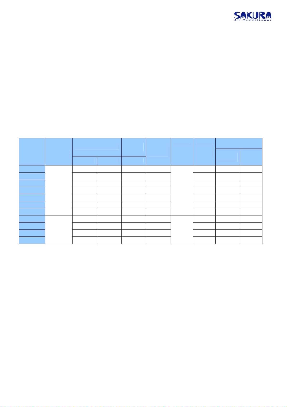
Operation
Startup
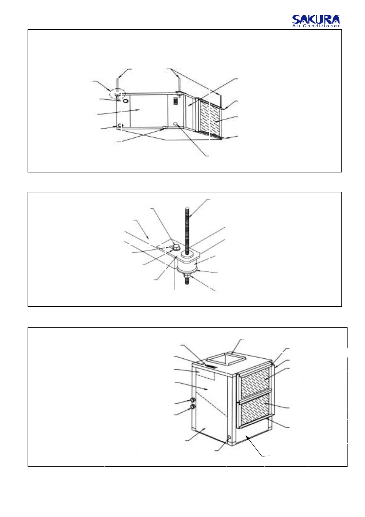
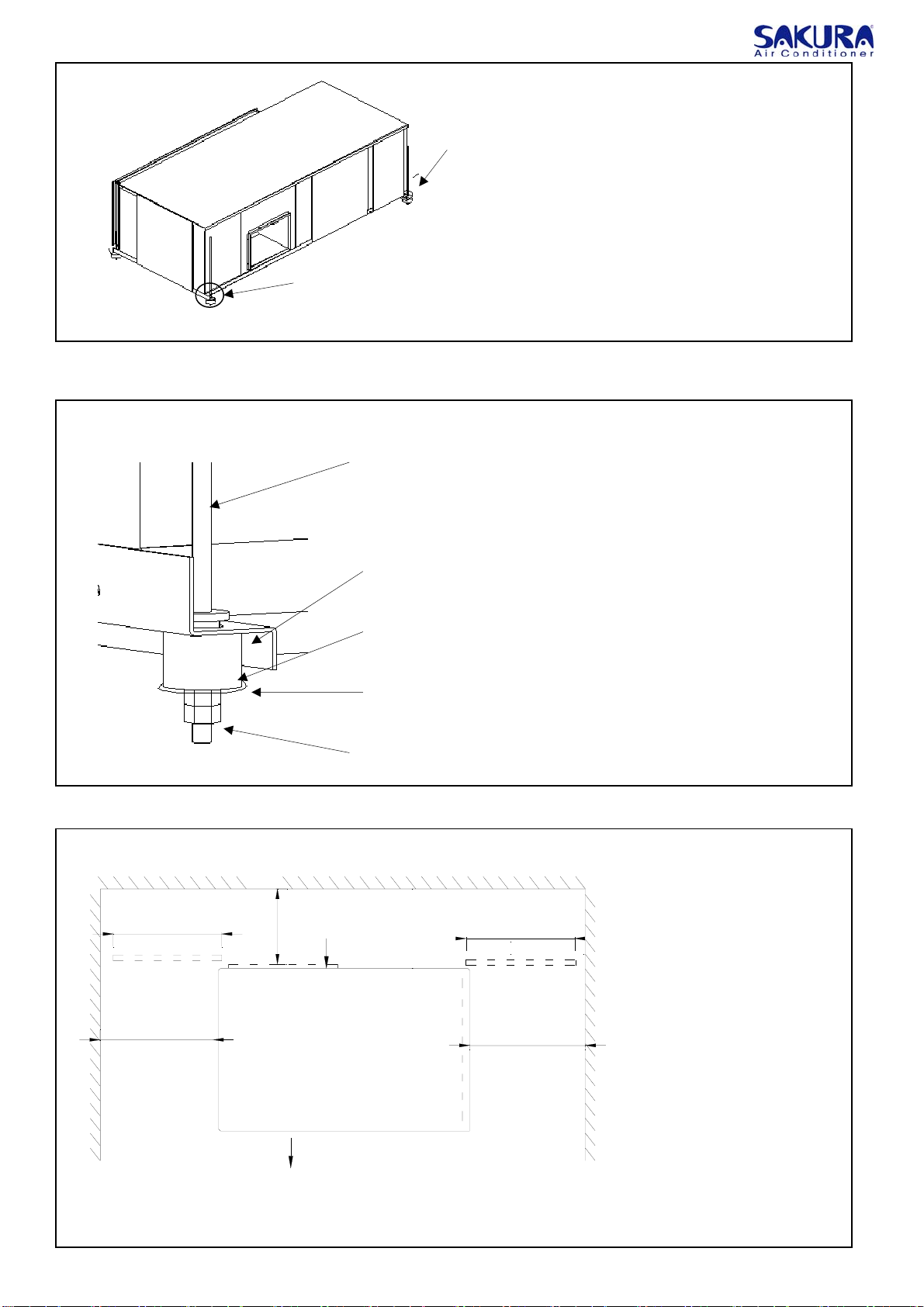
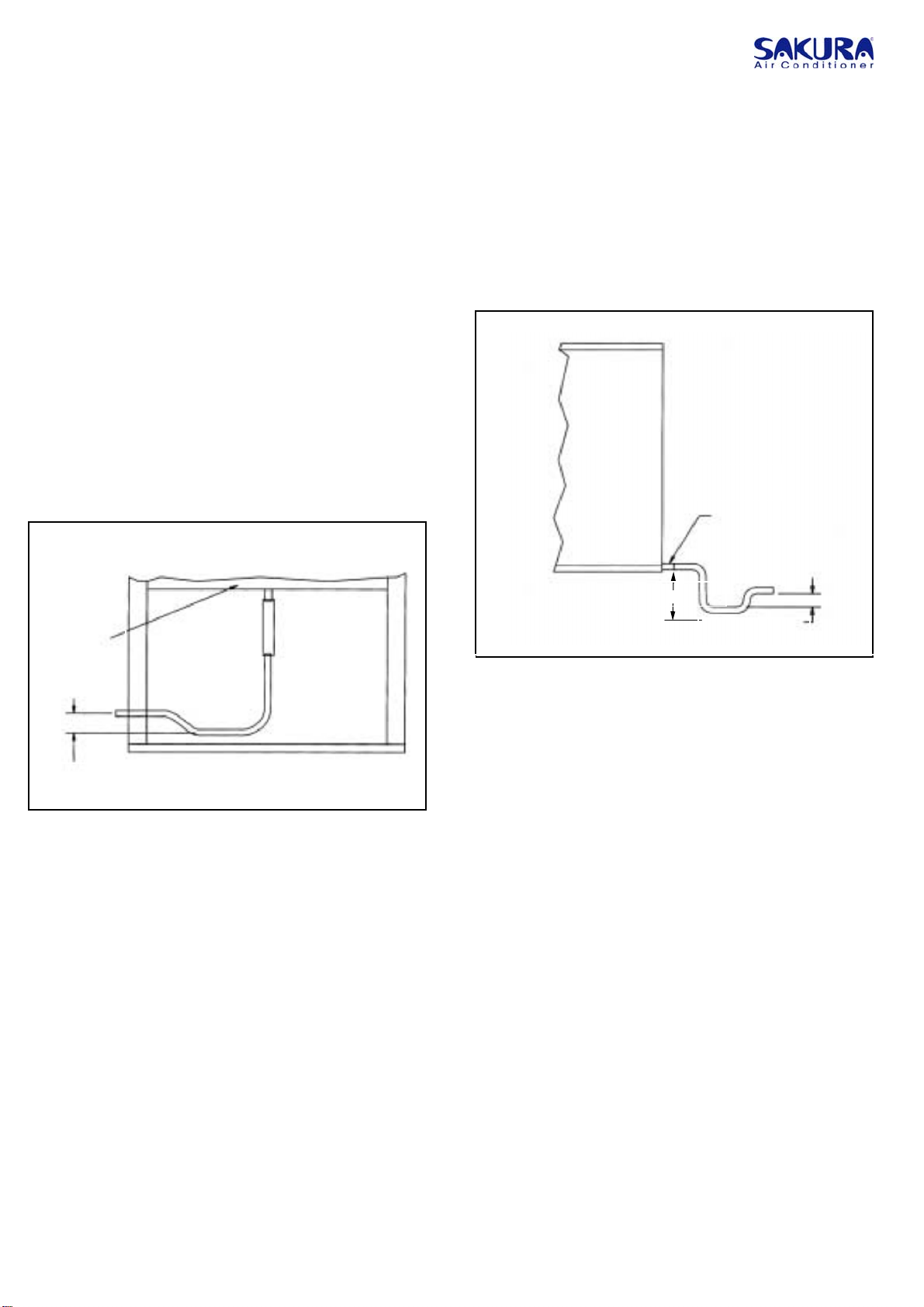
After installing, connecting ductwork and condensate lines and
wiring, unit is ready for startup. Check all internal wire
connections and connections to external control devices.
A disconnector with appropriate value should be mounted to
the wiring circuit.
6
Please do wiring according to the attached wire diagram. A
ticking sound can be heard when the unit is electrified. And then
you may please debug the unit in accordance with the manual of
thermostat.
1. Turn the thermostat fan switch to the “ON” position. Unit
blower should start.
Note: Unit may not start for 3 minutes due to anti-short
cycle relays.
2. Check the airflow and make sure no supply grilles or
duct dampers are closed to restrict airflow.
3. Set the thermostat temperature setting to low and turn the
systems switch to the heating mode.
4. Gradually increase the temperature to approximate room
temperature until unit starts.
5. After operating the unit for 10 minutes, check the air
temperature rise between supply and return airstreams. The
rise should be at least 10℃.
6. Using asurface pyrometer or other device, check entering
and leaving water temperatures. The recommended
temperature drop between entering and leaving water may
range from 3-5℃at 7℃EWT (Entering Water Temperature)
or from 3-8℃ at 21℃EWT(At heating mode in winter).
Note: If any of the above conditions do not exist, one or
more of the following problems exist: low airflow, low
water flow or unit not performing properly.
7. Set the thermostat system switch to cooling mode and
reduce temperature setting gradually until unit starts.
After operating the unit for afew minutes, check if it is
functioning properly and providing satisfactory cooling.
Note: Minimum dry bulb temperature drop between
supply and return airstreams should be about 9℃A
water temperature rise of 7℃-14℃could be anticipated
at relatively low water flow rates.
Maintenance
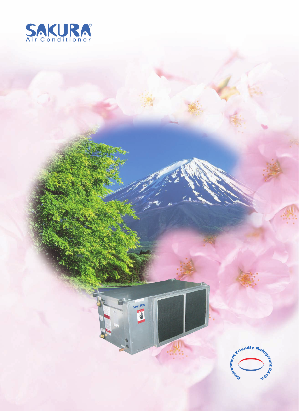
Air
Filters
Do not operate the heat pump without an air filter. Clean
the filters at least once every three months and more
frequently in dusty or unclean environments. Dirty filters will
cause inefficient heat pump performance.
Air Coil and Blower Wheel
Check the air coil and blower wheel at least once each
year and clean as necessary.
Compresso
Sakura heat pumps have been designed with switches that
protect the unit’s refrigerant system. They will automatically
shut down the compressor if refrigerant pressure rises too
high or drops too low.
General Service
Any repair or service on the unit must be performed by
qualified service personnel.
Factory-mounted Options
Cooling-only
Units are available for those applications requiring no
heating from the unit .
Extended range
Allows the unit to operate at lower entering water
temperature, includes insulated piping and insulated
coaxial heat exchanger.
25/50 mm filter
25 and 50 mm filter rack replaces the 10mm rack to allow for
more efficient and lasting 25 or 50mm filters
Field-mounted Options
Water Flow Switch
The Water Flow Switch will shut off the unit when the water
flow is smaller than limit value to protect the system
Flexible hose kits
Flexible hose kits are available in, 3/4-inch and 1-inch
diameters, 600mm and 900mm long. Each hose is
constructed of braided stainless steel and has steel fittings
with a swivel at one end. Hoses are rated at minimum 1000
kPa.