Salcom 15-15-8000 User manual

SEA AIR & LAND COMMUNICATIONS LIMITED, CHRISTCHURCH, NEW ZEALAND
15-15-8000
1U MiniPC
NZFS Sky TNPP
Flex Decode

NZFS 15-15-8000 VisualPet User’s Manual Iss: VPetNZFS 06/09
Sea Air & Land Communications Ltd. Page 2 of 23
15-15-8000 1U MiniPC Vpet Message Router
The 15-15-8000 is an enhanced message router design using the intelligence of Salcom VisualPet
software.
This combination creates a new direction for message routing, display and logging. VisualPet
allows new technologies to be bought to the remote sites including TCP/IP based protocols like
SMTP (email), HTTP (web browser), TNPP via IP and remote login / management. New message
delivery options like SMS can also be implemented.
The configuration for the NZFS 15-15-8000 uses a Pentium500 miniPC running WindowsXP and
Salcom VisualPet to decode inbound messages from either a Salcom Flex Decoder or the NZFS
Sky Paging Network and pass these messages to a Salcom 15-15 Paging Transmitter.
The 15-15-5000 or 15-15-9000 (15-15-5000 + Intergrated Flex Receiver) Transmitter retains all the
current options required by NZFS – Four programmable inputs, local test page button, PDT selcall
acknowledge and Sky Decoder reset timer.
VisualPet contains a database of valid pagers and will convert the received Sky or Flex Pager RIC’s
into valid codes for transmitting to crews.

NZFS 15-15-8000 VisualPet User’s Manual Iss: VPetNZFS 06/09
Sea Air & Land Communications Ltd. Page 3 of 23
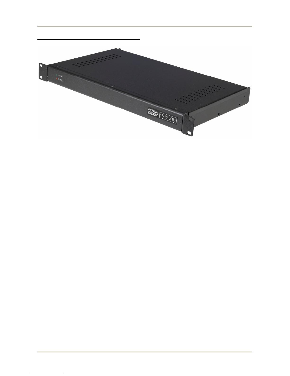
Additional Features
The 15-15-8000 supports the use of a standard LCD display along with connections to four RS232
serial ports, one Ethernet port, two USB, Keyboard and mouse.
The Ethernet port allows remote connection or the use or TCP/IP protocols for message reception or
delivery.
The LCD display can be switched off for power savings without any compromise of 15-15-8000
functionality.
VisualPet can be configured to display and transmit ALL Sky TNPP messages for system tests or
diagnostics.
Log files can be created for each Stations messages sent and saved on a daily basis. These logs can
be retrieved using the remote login feature. Eg:
00:30:01 0999746 (HALC321, FEIL281) 111-VEG SANDON RD HALCOMBE. (XStr TE
RAKEHOU RD/MOUNT STEWART HALCOMBE RD) .TOI TOI ON FIRE THREATENING
SHELTER BELT. #W748388.
00:30:04 0999578 (HALC321, FEIL281) 111-VEG SANDON RD HALCOMBE. (XStr TE
RAKEHOU RD/MOUNT STEWART HALCOMBE RD) .TOI TOI ON FIRE THREATENING
SHELTER BELT. #W748388.
00:32:18 0999102 (MANU301) 111-MIN TAKANINI. (XStrMILL RD/AIRFIELD RD) .CAR
FIRE. #A707046.
Due to the flexibility of the VP Router software, changes to the display content and layout are
easily implemented. The software also allows the addition of new protocols and data types without
hardware changes.
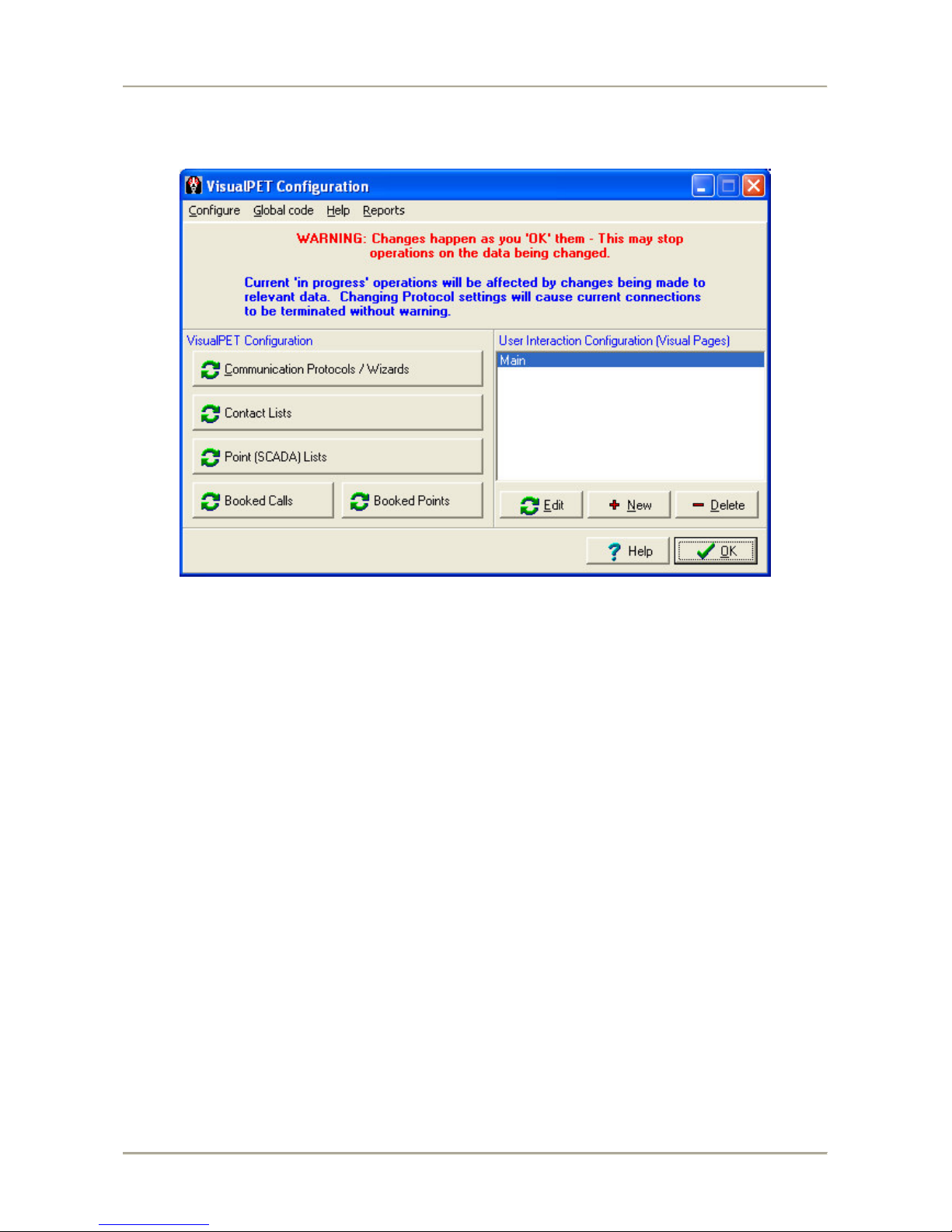
VisualPet – Security
To access any configuration, contacts or router screens within VisualPet a password is required.
This stops unauthorized users from changing contacts or setting within VP Router and possibly
causing the system to stop working correctly.
The default password is: salcom for access to any password configured screens

NZFS 15-15-8000 VisualPet User’s Manual Iss: VPetNZFS 06/09
Sea Air & Land Communications Ltd. Page 4 of 23
VP Router – Configurations
There are two default configurations for the 15-15-8000, TNPP Sky or Flex Decode, which can be
interchanged using a simple tool called Vpet Config (see Vpet Config section below)
Once a configuration has been selected the 15-15-8000 will only need administration of the crew
pager codes (contacts).
The 15-15-8000 does not require any mouse or keyboard to operate.
Connection to the 15-15-8000 for administration is done via a local Keyboard and Mouse or Cat5
Ethernet crossover cable or via connection across the NZFS IP network.
The 15-15-8000 runs VNC as the remote desktop admin tool. The 15-15-8000 is factory configured
with an IP of 192.168.1.150 and once VNC is connected the password of “salcom” will bring up the
15-15-8000 desktop.
Once a configuration has been installed the main window label will display the configuration and
version number.
Ie:
NZ FIRE SKY PAGING TERMINAL V2.1
NZ FIRE FLEX PAGING DATA TERMINAL V2.1

NZFS 15-15-8000 VisualPet User’s Manual Iss: VPetNZFS 06/09
Sea Air & Land Communications Ltd. Page 5 of 23
Sky TNPP Configuration
The crew pager codes are controlled in VisualPet as “Contacts”. Each contact will be made up of
the receive RIC code sent via TNPP across the Sky network (“Label”) and the destination code for
delivery through the 15-15 Transmitter.

NZFS 15-15-8000 VisualPet User’s Manual Iss: VPetNZFS 06/09
Sea Air & Land Communications Ltd. Page 6 of 23
A Sky decoder will output serial RS232 data to the NZFS VP Router 15-15-8000, this data consists
of NZFS implementation of TNPP data packets.
Sky serial data example:
[01]e004ee777749[02]FA00`01234567THIS IS A TEST PERIODIC PAGE SEQUENTIAL
NUMBER 9651 [03][8b][8e]
NZFS Contacts
To add a contact File > Configure from the main screen.

NZFS 15-15-8000 VisualPet User’s Manual Iss: VPetNZFS 06/09
Sea Air & Land Communications Ltd. Page 7 of 23
Then from the menu shown click the button labeled Contact Lists.

NZFS 15-15-8000 VisualPet User’s Manual Iss: VPetNZFS 06/09
Sea Air & Land Communications Ltd. Page 8 of 23
The screen below will appear and from here contacts can be added, modified and deleted:
The opening/default tab is Contact Details
The List of all Contacts shows current contacts within VP Router. The highlighted contact
(999204=Broadcast) is therefore the contact whose details are shown under the Contact Details
tab.
The In Service box allows the option of taking a contact out of service without losing the detail.
The Label is the contacts ID within the router. This is the field where the TNPP RIC that will be
decoded is added. NOTE: Do not include leading zeros ie if code = 0999205 enter 999205
The Name / Comment field is where you can attach a more suitable name or comment about a
contact.
The Tag field can be used for the Station name.
The AutoText and TimeStamp options allow messages to contain incremental numbering plus
current Time and Date stamps

NZFS 15-15-8000 VisualPet User’s Manual Iss: VPetNZFS 06/09
Sea Air & Land Communications Ltd. Page 9 of 23
The Destination tab is used to select where a message to the contact is to be delivered.
The Destinations box will show a list of installed protocols for message delivery.
The above example has two destinations with only the TNPP_Out option having a contact entered.
The TNPP_Out destination requires the seven digit RIC code ( 0384309 ) in the Contact details.
This is the RIC code the message will be sent to by the 15-15 transmitter.
The function (Level) can be changed in the drop down menu from 1 to 4
Once all contact details are entered a click on the OK will save the settings.

NZFS 15-15-8000 VisualPet User’s Manual Iss: VPetNZFS 06/09
Sea Air & Land Communications Ltd. Page 10 of 23
PDT Ack, Printer Output and Display Message
Control of the PDT Ack relay, content to the Printer or Displaying the message for the current
Contact is achieved by using the View as Text button. By pressing the button a dialog window will
open as below:
Printer Output is controlled from the line states:
Print=F
This means for the contact selected there will not be any output sent to printer. By changing the
string to:
Print=T
The printer output will be enabled.
Note that if there no “Print=T” or “Print=F” then the default is print output enabled
PDT Ack is controlled from the line states:
Ack=F
This means for the contact selected there will not be any acknowledge output on the relay. By
changing the string to:
Ack=T
The PDT Ack relay output will be enabled.
Note that if there no “Ack=T” or “Ack=F” then the default is PDT Ack output disabled
Display Message is controlled from the line states:
Display=F
This means for the contact selected the message received will NOT be shown on the main display.
Display=T
Any received message will be displayed.
Note that if there is no “Display=T” or “Display=F” then all messages will be displayed
Once the Printer, Display and PDT Ack setting are completed click OK to save and exit.
The Close button bottom right of the Contacts window will return user to the Main screen.

NZFS 15-15-8000 VisualPet User’s Manual Iss: VPetNZFS 06/09
Sea Air & Land Communications Ltd. Page 11 of 23
Flex Decode Configuration
The Flex receiver doesn’t output the actual received RIC, instead it sends the memory location of
the programmed field where the flex RIC is stored.
ie: If the Flex receiver is programmed to decode 998765 in memory location 1, when a message is
received for RIC 998765 the serial data will contain only the memory location.
Eg: Memory Location 1 is programmed to 998765 and a message is received for that RIC, therefore
serial data is:
FLEX (1)This is the message<cr>

NZFS 15-15-8000 VisualPet User’s Manual Iss: VPetNZFS 06/09
Sea Air & Land Communications Ltd. Page 12 of 23
Contacts
The contacts for the Flex configuration are based on the memory location data received from the
Daviscomm Flex receiver. The Daviscomm memory locations are sequential from 1 to 16, with 16
programmed to receive the Telecom Periodic test message.
The List of all Contacts shows current contacts within VP Router. The highlighted contact
(1=Station T/O) is therefore the contact whose details are shown under the Contact Details tab.
The In Service box allows the option of taking a contact out of service without losing the detail.
The Label is the contacts ID within the router. This is the field where the Daviscomm memory
location is entered.
The Name / Comment field is where you can attach a more suitable name or comment about a
contact.
The Tag field can be used for the Station name.
The AutoText and TimeStamp options allow messages to contain incremental numbering plus
current Time and Date stamps

NZFS 15-15-8000 VisualPet User’s Manual Iss: VPetNZFS 06/09
Sea Air & Land Communications Ltd. Page 13 of 23
The Destination tab is used to select where a message to the contact is to be delivered.
The Destinations box will show a list of installed protocols for message delivery.
The above example has three destinations with only the Transmitter option having a contact
entered. The Transmitter destination requires the Daviscomm memory location in the Contact
details.
The 15-15-9000 Transmitter is programmed to accept the Daviscomm Flex protocol, this means the
transmitter is able to receive messages from VisualPet or directly from the Daviscomm Flex
Receiver.
The function (Level) , Family, Rate, Pager Type are not supported for the Daviscomm Flex
receivers.
The translation from the Daviscomm memory location to an actual Pager RIC is done by the 15-15-
9000, The 15-15 programming also controls the Pager Level .
Once all contact details are entered a click on the OK will save the settings.

NZFS 15-15-8000 VisualPet User’s Manual Iss: VPetNZFS 06/09
Sea Air & Land Communications Ltd. Page 14 of 23
Printer Output and Display Message
Control of content to the Printer or Displaying the message for the current Contact is achieved by
using the View as Text button. By pressing the button a dialog window will open as below:
Printer Output is controlled from the line states:
Print=F
This means for the contact selected there will not be any output sent to printer. By changing the
string to:
Print=T
The printer output will be enabled.
Note that if there no “Print=T” or “Print=F” then the default is print output enabled
Display Message is controlled from the line states:
Display=F
This means for the contact selected the message received will NOT be shown on the main display.
Display=T
Any received message will be displayed.
Note that if there is no “Display=T” or “Display=F” then all messages will be displayed
The ability to Ack a message is done in the 15-15-9000 programming using the RIC translation
table. (see 15-15-9000 manual)
Once the Printer and Display setting are completed click OK to save and exit.
The Close button bottom right of the Contacts window will return user to the Main screen.

NZFS 15-15-8000 VisualPet User’s Manual Iss: VPetNZFS 06/09
Sea Air & Land Communications Ltd. Page 15 of 23
Test Messages
A test message can be sent from VisualPet by clicking the on the main window:
A window allows selection of a contact and message to be sent by clicking the Send button.
The test message window will automatically close after the send button has been pressed.
Reprinting Messages
The 15-15-8000 allows any onscreen messages to be reprinted on demand. There are two methods
for reprinting the messages:
1. Using an attached mouse, click the button beside the message window to resent it to the
attached printer.
2. By pressing the Keys 1 to 4 on an attached full size or numeric only keyboard. Key 1
will print the top window, Key 2 the next window down etc.. Key 4 prints the lowest
window.

NZFS 15-15-8000 VisualPet User’s Manual Iss: VPetNZFS 06/09
Sea Air & Land Communications Ltd. Page 16 of 23
Message Router
The message router allow users to see the transactions and messages being accepted and delivered
by VisualPet. To view the router screen use File > View Router, this will display the screen below:
The router screen displays information about each message into and out of VisualPet.
The top left screen shows all messages that have been recently routed.
The bottom left shows the status and port settings for all running protocols. (nb: you may see
protocols here that were not available in the delivery options for a contact, this is because some of
the protocols shown here are input only).
The Clear Onscreen Log button will clean the operation log screen
The Operation History top right will show how many messages have been successfully routed, are
in progress or have failed.

NZFS 15-15-8000 VisualPet User’s Manual Iss: VPetNZFS 06/09
Sea Air & Land Communications Ltd. Page 17 of 23
Configuration Changes – Vpet Config.exe
Before making changes to the configuration of VisualPet the application must be closed.
Use File > Close to shut down VisualPet, password if requested is ‘salcom”
On the 15-15-8000 desktop is an icon to run VpetConfig.exe. Once VpetConfig is running there are
a range of options for making VisualPet changes.
The Backup option will copy the current VisualPet configuration to a backup folder. It is
recommended that before making changes a backup is made.
The Restore from Backup option will allow navigation to a folder containing a previous
configuration. Before using the Restore option the password field will need to be populated, default
is “salcom”
Reset to Flex installs a default Flex configuration which requires the contacts data to be configured
before using the 15-15-9000. Before using the Reset option the password field will need to be
populated, default is “salcom”
Reset to Sky installs a default Sky configuration which requires the contacts data to be configured
before using the 15-15-9000. Before using the Reset option the password field will need to be
populated, default is “salcom”
Once the option has been completed Exit the VpetConfig application and restart VisualPet from the
Desktop icon.

NZFS 15-15-8000 VisualPet User’s Manual Iss: VPetNZFS 06/09
Sea Air & Land Communications Ltd. Page 18 of 23
Salcom VisualPet – Software Overview
VisualPet software configurations allow the routing of messages from multiple input sources to
multiple output destinations, ie:
Inputs:
Salcom 11-36 Fone Page
PET / TAP TNPP Free Form Scripted Protocols
Email ( SMTP / POP ) Internet Selcall X25 Pacnet
Outputs:
Salcom Paging Transmitters PET / TAP Selcall Email (SMTP / POP )
Free Form Scripted Protocols Internet X25 Pacnet TNPP
The Free Form Scripted Protocols allow scripted configuration of just about any industry protocol.
Salcom can create protocols to suit any application where a message or packet of information needs
to be monitored, routed and delivered.
Protocols can be configured to operate using RS232 serial or TCP/IP. Eg: TNPP or PET over IP for
long distance or network message delivery connections
Salcom can create and add specific protocols for any type of message or information delivery,
including SCADA applications. Protocols for handling SMS from specific cellular modems, SMS
IP based gateways, XML data via IP, Flex and POCSAG Decoders are other examples.
Each message route allows delivery to multiple destinations from a single source message. The VP
Router can translate contact, message type, and specific protocol information for any inbound and
outbound message. For example an inbound PET message can be forwarded onto a pager through a
12-62 with a copy sent via email and TNPP to another paging vendor.
Multiple inbound and outbound messages can be handled at one time, with complete logging of all
message transactions.
A message delivery failure from a lost serial or ethernet connection can generate an alarm route
which will contain the connection, contact and message that failed.
Contacts within the router are easily added, modified and deleted.

NZFS 15-15-8000 VisualPet User’s Manual Iss: VPetNZFS 06/09
Sea Air & Land Communications Ltd. Page 19 of 23
15-15-8000 Connections
Note: position of connectors may differ depending on 15-15-8000 cabinet model.
The Power connector is the Salcom standard 15-15 plug. 12V DC.
Current consumption, up to 3A on startup, Typ 1A fully operational.
Com1: Connect to the DavisComm Flex receiver
Com2: Connect this port to the Sky Decoder output
Com3: Connect this port to the 15-15-5000 Transmitter
Com4: Connect this port to the Printer
The Network port is used for connection via the VNC remote management software.
The PS2 port can be used to add either a mouse or keyboard (both using supplied adapter)
-- see the USB ports.
The VGA connector is for connecting the Display.
The USB will support a mouse and keyboard, connecting a mouse or keyboard via USB will mean
the 15-15-8000 will not require a reboot to recognize new hardware.
The USB port will also support a Flash Drive for the addition or removal of software and/or log
files etc…

NZFS 15-15-8000 VisualPet User’s Manual Iss: VPetNZFS 06/09
Sea Air & Land Communications Ltd. Page 20 of 23
15-15-8000 MiniPC Specifications
• CPU: AMD Geode® LX800 processor, up to 500 MHz
• System Memory: 1 x SODIMM socket, support Double Data Rate
(DDR) SDRAM, Max 512 MB, accept 128/256/512 MB, DDR333
SDRAM
• 2nd Cache Memory: 128 KB on the processor
• System Chipset: AMD Geode LX800
• BIOS: AWARD 2Mbit Flash BIOS
• Watchdog timer: 255 levels timer interval
• Expansion Interface: PC/104
• Battery: Lithium 3V/196 mAH
• Power management: APM 1.2, ACPI supported
• Enhanced IDE interface: One channels supports up to two EIDE devices. BIOS auto-detect, PIO Mode 3 or
Mode 4, supports UDMA 33/66 mode
• Serial ports: Four serial ports, 4 ports for RS-232 (COM1: DB9 connector on the front site, COM2, 3, 4: by box
header), 1 port for RS-422/485 (CN18: by box header with auto-flow controller). COM2,3, 4 is with a Hirose connector
40 pin
• Parallel port: One parallel port, supports SPP/EPP mode
• Keyboard/mouse connector: Supports one standard PC/AT keyboard and a PS/2 mouse
• Audio: Support AC97 Audio stereo sound
• USB: Four USB 2.0 compliant universal serial bus ports
• Solid State Disk (SSD) Supports one 50-pin socket for CFC type I (type II optional)
1.3.2 VGA/LVDS Interface
• Chipset: AMD Geode LX800
• Memory Size: Optimized Shared Memory Architecture, support 64MB frame buffer using system memory
• Resolution: CRT resolution: up to 1600 x 1200 x 16 bpp at 100 Hz and up to 1024 x 768 x 32 bpp at 60 Hz for TFT
LCD
• LCD Interface: Supports up to 24-bit TFT LCD (TTL signal) (PCM-9375F)
• LVDS Interface: Supports one channel 18-bit LVDS Interface (PCM-9375E)
• Dual Simultaneous Display: CRT + LCD, CRT + LVDS
Popular Network Router manuals by other brands

MeshNetworks
MeshNetworks MEA PWR6300 user guide

Qlogic
Qlogic SANbox 6142 supplementary guide

3One data
3One data IES7110-3G Series user manual

Outdoor Router
Outdoor Router EZR30 Series user manual

red lion
red lion ET-8EG-MIL-1 user manual

Planet
Planet 85M Powerline to Ethernet Bridge with 4-Port Switch... user manual