Salford 700 User manual

2011 MODEL 700 40FT C-SHANK CULTIVATOR
ASSEMBLY AND PARTS MANUAL

Salford Farm Machinery Ltd.
700 40' C-Shank Cultivator Assembly and Parts Manual 2011
09-2011
Table of Contents
General
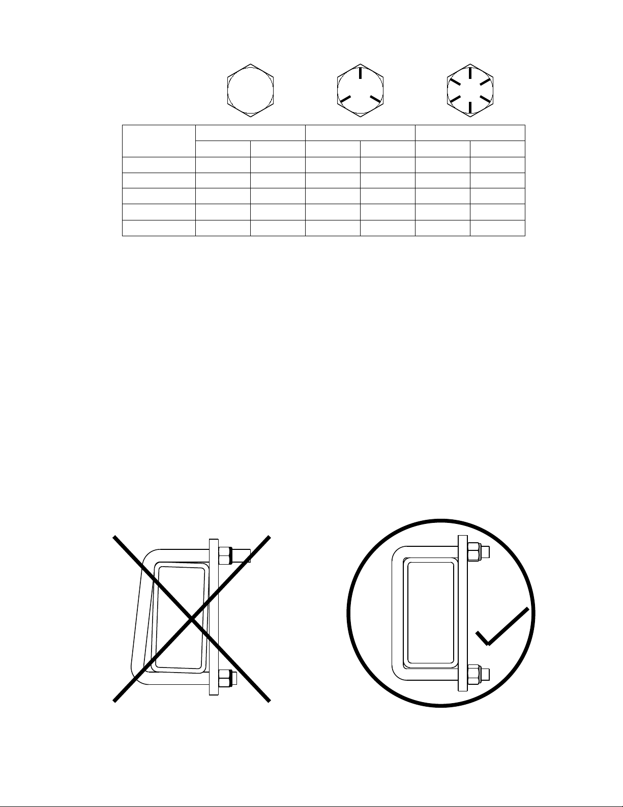
Salford Recommended Torque Values .........................................................................................................3
Torque Values for Tires ................................................................................................................................4
Pressure Values for Tires..............................................................................................................................5
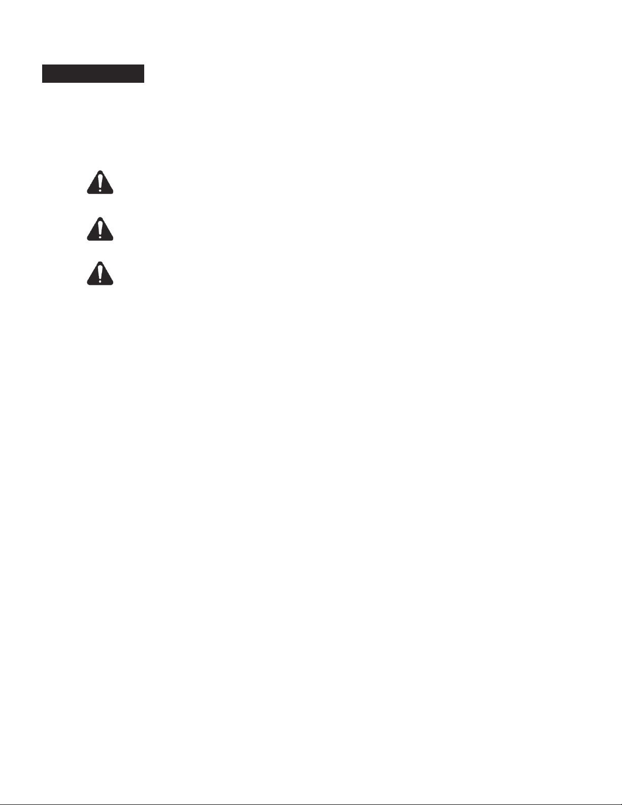
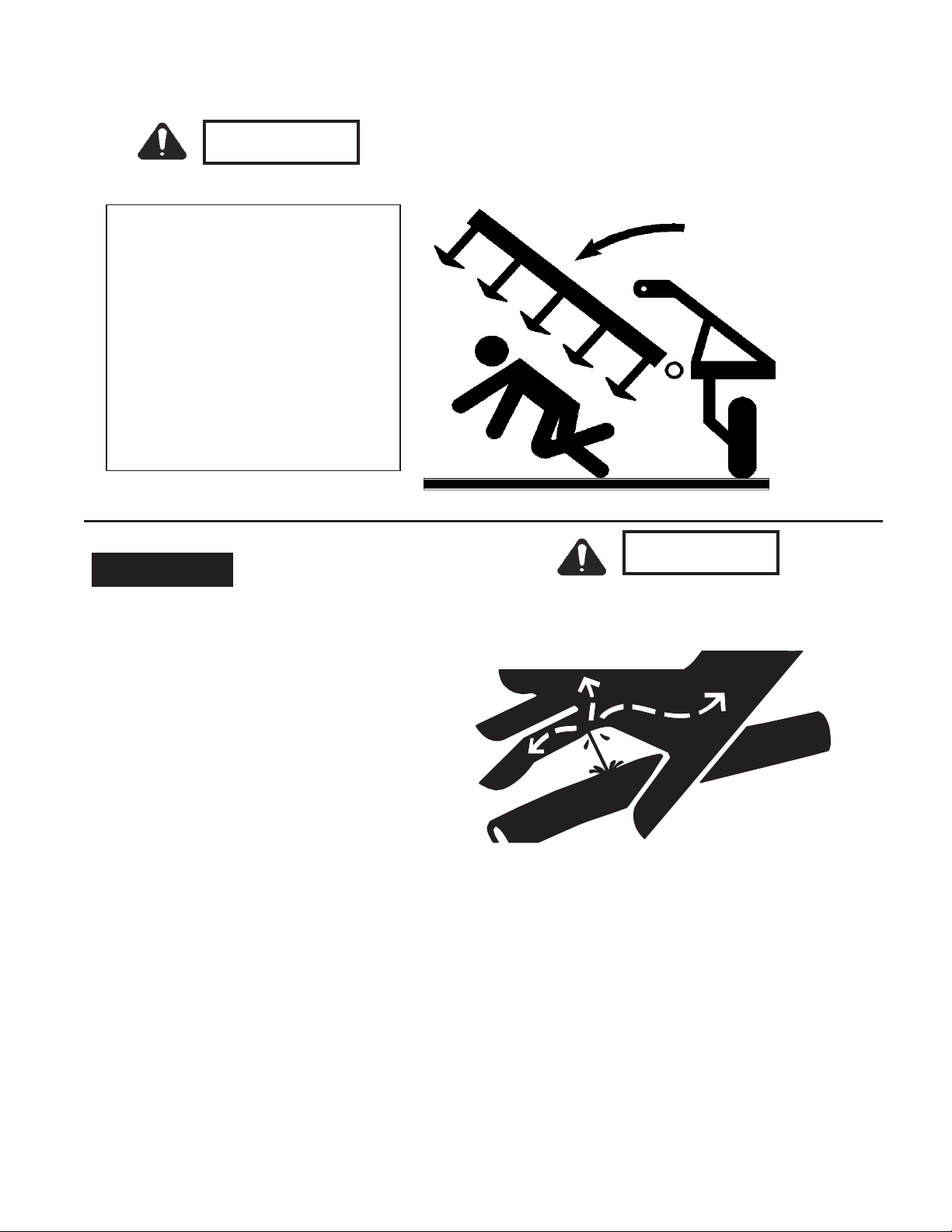
General Safety Precautions..........................................................................................................................6
Frame & Tongue
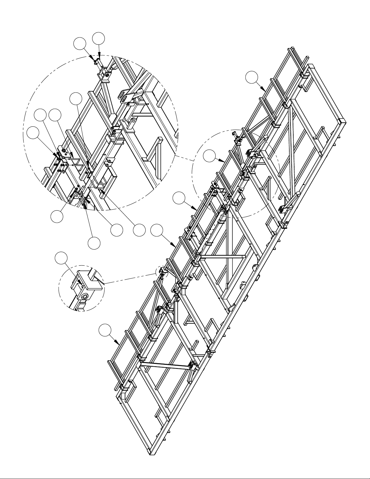
Primary Wing Installation ............................................................................................................................8
Front Bar Installation .................................................................................................................................10
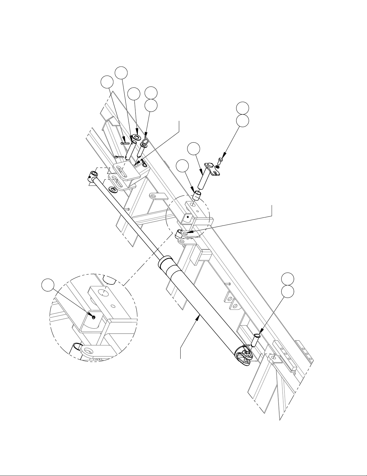
Standard Tripod Installation.......................................................................................................................12
Land Hugger Tripod Installation................................................................................................................13
Standard Tripod & Depth Control Installation...........................................................................................14
Land Hugger Tripod & Depth Control Installation....................................................................................16
Tongue Installation.....................................................................................................................................18
Telescope Mount Hose Holder...................................................................................................................20
Axles
Wheel & Axle Layout ................................................................................................................................21
8000lb Axle Installation.............................................................................................................................22
8000lb Axle Assembly ...............................................................................................................................24
5000lb Axle Installation.............................................................................................................................26
5000lb Axle Assembly ...............................................................................................................................28
Standard Gauge Wheel Assembly & Parts.................................................................................................30
Land Hugger Gauge Wheel Assembly & Parts..........................................................................................32
4000lb & 5000lb Hub & Spindle Assembly ..............................................................................................34
Shank Parts
Shank Assembly & Parts............................................................................................................................36
Shank Head Assembly & Parts ..................................................................................................................38
40ft - 7in C-Shank Layout .........................................................................................................................40
Harrow Parts
40ft - 7in Harrow Layout ...........................................................................................................................41
Harrow Installation ....................................................................................................................................42
Harrow Arm Assembly ..............................................................................................................................44
Tine Harrow Assembly ..............................................................................................................................46
14” Roller Assembly ..................................................................................................................................48
Hydraulics & Lights
Axle Lift Hydraulics ..................................................................................................................................50
Wing Lift Hydraulics .................................................................................................................................52
Lights & SMV Installation.........................................................................................................................54
Decal Layout..............................................................................................................................................56
Decal Legend .............................................................................................................................................59
Optional Tow Hitch
Tow Hitch Installation................................................................................................................................60
Independent Tow Hitch Hydraulics ...........................................................................................................61
Shared Tow Hitch Hydraulics ....................................................................................................................62

09-2011 Page 3
Salford Farm Machinery Ltd.
700 40' C-Shank Cultivator Assembly and Parts Manual 2011
6$/)25' 5(&200(1'(' 72548( 9$/8(6
BOLT SIZE GRADE 2 GRADE 5 GRADE 8
ft-lbs Nm ft-lbs Nm ft-lbs Nm
1/2"NC 50 68 75 102 105 142
5/8"NC 90 122 150 203 210 285
3/4"NC 160 217 270 366 375 508
7/8"NC 145 197 395 536 610 827
1"NC 210 285 590 800 910 1234
127(6: These recommended torque values are applicable when applied to the nut
only. These recommended torque values are approximate only. The torque-tension
relationship is affected by lubrication, surface finish, thread fit, plating, lock-washers, etc.
'2 127 use these values if a different torque value or tightening procedure is given for
a specific application. Torque values listed are for general use only. Check tightness of
fasteners periodically.
Shear bolts are designed to fail under predetermined loads. Always replace shear bolts
with identical grade.
Fasteners should be replaced with the same or higher grade. If higher-grade fasteners
are used, these should only be tightened to the strength of the original.
Make sure fasteners threads are clean and that you properly start thread engagement.
This will prevent them from failing when tightening.
WARNING Both sides of the u-bolt
Do not tighten one side of the must be tightened equally.
u-bolt before the other side.
Salford Recommended Torque Values
Return to Contents

Salford Farm Machinery Ltd.
Page 4 09-2011
700 40' C-Shank Cultivator Assembly and Parts Manual 2011
WARNING
Maintain proper torque to provide safe and secure
attachment of the wheel hub/drum. Improperly tightened
wheel nuts can cause the wheel to separate from the wheel mounting surface
during operation. This could result in property damage, serious personal injury,
or possibly loss of life.
NOTE
- If wheel does not have chamfers to match profile of the nuts, use flat side of
nuts against rim face.
Install all lug nuts/bolts by hand to prevent cross threading and tighten lug nuts/bolts
following the steps and tightening sequence diagram below.
STEP 1) Torque to 20-25 ft•lbs following the appropriate pattern below.
STEP 2) Torque to 55-60 ft•lbs following the appropriate pattern below.
STEP 3) Torque to final ft•lbs rating (see bolt size below) following the
appropriate pattern below.
NOTE
- Recheck the torque settings of lug nuts/bolts after 10km (6 miles) and again
after 50km (30 miles). Periodically and at the beginning of each season check the
condition and the torque of the lug nuts/bolts.
5
3 6
4
1
2 2
1
4
6
3
5
7
8
5
67
1
2
3 10
8
49
6 LUG BOLT PATTERN 8 LUG BOLT PATTERN
10 LUG BOLT PATTERN
Lug Nut/Bolt TIghtening Sequence
Bolt Size (Hub Size)
Final Torque
1/2" dia. bolt (up to 3000 lb hubs)
85 ft•lbs
9/16" dia. bolt (4000 - 5000 lb hubs)
120 ft•lbs
5/8" dia. bolt (5500 - 12000 lb hubs)
170 ft•lbs
3/4" dia. bolt (16000 - 20000 lb hubs) 300 ft•lbs
7/8" dia. bolt (25000 lb hubs)
450-500 ft•lbs
Torque Values for Tires
Return to Contents

09-2011 Page 5
Salford Farm Machinery Ltd.
700 40' C-Shank Cultivator Assembly and Parts Manual 2011
N
N
Deep dish
11L
245
425
Tires to install
deep dish in:
N
N
Deep Dish
12.5L
305
Tires to install
deep dish out:
If bolts/nuts are coned, ensure
proper seating in chamfer on rim.
Ensure proper inflation of each tire for safe operation and extended tire life.
NOTE
- Periodically and at the beginning of each season check the condition and the
pressure of each tire.
Tire Installation Direction
Do not rely on valve stem for orientation of
tires. It may face in or out on different rims.
Measure both sides of tire in to rim face. Install the
deep side in or out according to the instructions below.
Pressure [psi]
Pressure [bar]
Tire Size
25 [psi]
1.72 [bar]
23.1 x 26 (16 ply)
35 [psi]
2.41 [bar]
Load Range C - 11L15
36 [psi]
2.48 [bar]
28L26 (16 ply)
52 [psi]
3.58 [bar]
30.5LR32 (181A8/B)
65 [psi]
4.48 [bar]
Load Range D - 11L15
- 12.5L15
90 [psi]
6.20 [bar]
Load Range F - 11L15
- 12.5L15
Truck Tires - 245/70R19-5
- 305/70R22-5
- 425/60R22-5
Pressure Values for Tires
Return to Contents

Salford Farm Machinery Ltd.
Page 6 09-2011
700 40' C-Shank Cultivator Assembly and Parts Manual 2011
Signal Words
The words DANGER, WARNING or CAUTION are
used with the safety alert symbol. Learn to
recognize the safety alerts, and follow the
recommended precautions and safe practices.
Three words are used in conjunction with the safety-alert symbol:
DANGER
WARNING
Indicates an imminently hazardous situation that, if not
avoided, will cause DEATH OR VERY SERIOUS INJURY.
Indicates a potentially hazardous situation that, if not
avoided, could cause DEATH OR SERIOUS INJURY.
CAUTION Indicates a potentially hazardous situation that, if not
avoided, may result in MINOR or MODERATE INJURY.
Replace any DANGER, WARNING, CAUTION or
instructional decal that is not readable or is missing.
The location and part number of these
decals is identified later in this section of the
manual.
The words Important and Note are not related to
personal safety but are used to give
additional information and tips for
operating or servicing this equipment.
IMPORTANT: Identifies specia l instructions or
pr ocedures whic h , if not strictl y
observed could result in damage to, or
destruction of the machine, process or
its surroundings.
NOTE: Indicates points of particular interest for more efficient and convenient repair or operation.
A CAREFUL OPERATOR IS THE BEST INSURANCE AGAINST AN ACCIDENT !
General Safety Precautions
Return to Contents

09-2011 Page 7
Salford Farm Machinery Ltd.
700 40' C-Shank Cultivator Assembly and Parts Manual 2011
Wings may fall rapidly
causing injury.
Always stay clear of wings
when being lowered, raised
or in a elevated state.
Always use lockup device
provided when raised.
Ensure cylinder is completely
filled with hydraulic fluid to
avoid unexpected
movement.
• DO NOT search for high pressure hydraulic
leaks without hand and face protection. A
tiny, almost invisible leak can penetrate skin,
thereby requiring immediate medical
attention.
• Use cardboard or wood to detect leaks –never
your hands.
• Double check that all is clear before
operating hydraulics.
• Never remove hydraulic hoses or ends
with machine elevated. Relieve hydraulic
pressure before disconnecting hydraulic
hoses or ends.
• Maintain proper hydraulic fluid levels.
• Keep all connectors clean for positive connections.
• Ensure all fittings and hoses are in good condition.
• Do not stand under wings.
General O
Hydraulics
DANGER
DANGER
General Safety Precautions
Return to Contents

Salford Farm Machinery Ltd.
Page 8 09-2011
700 40' C-Shank Cultivator Assembly and Parts Manual 2011
6 7
3
10
9
8
5
4
11
2
1
REFER TO
HYDRAULIC LAYOUT
FOR CYLINDER SIZE
Place wing lock pins through
lugs when wings are folded
to hold wings in position for
transport or storage
Wing lock
pin storage
CYLINDER PORTS
FACE REAR OF
MACHINE
12
Primary Wing Installation
Return to Contents

09-2011 Page 9
Salford Farm Machinery Ltd.
700 40' C-Shank Cultivator Assembly and Parts Manual 2011
CAUTION
Connect hoses and charge the wing fold cylinders with fluid
following the procedure in the wing fold hydraulics section of
this manual before connecting rod ends of the cylinders.
ITEM
QTY
PART NO.
DESCRIPTION
1 8
GBB175150200
1 3/4" x 1 1/2" x 2" LG. HARD BUSHING
2 4
GPH2400814F
1 1/2" x 8 1/4" LG. HARD PLATE PIN
3 4
B1015
5/8 X 1 1/2" PLATED BOLT
4 4
BL10
5/8" LOCKWASHER
5 4
GPH20006A06
1 1/4" x 6" HARDENED PIN - 2 HOLES
6 4
GPHF2000312H05
1 1/4" x 3 1/2" SHOULDER PIN HARDENED W/ FLATS
7 4
BSC0520
5/16" x 2" COTTER PIN
8 8
BSC0620
3/8" x 2" COTTER PIN
9 8
BF20S
1 1/4" SAE WASHER
10 2
GP1600414C04
1" x 4 1/4" RING & WASHER PIN
11 2
GHP9
#9 HAIR PIN
12 4
GF1610
1/8" NPT GREASE FITTING
Primary Wing Installation
Return to Contents

Salford Farm Machinery Ltd.
Page 10 09-2011
700 40' C-Shank Cultivator Assembly and Parts Manual 2011
4
2
3
1
5
8
9
6
7
7
10
7
11
7
12
13
Front Bar Installation
Return to Contents

09-2011 Page 11
Salford Farm Machinery Ltd.
700 40' C-Shank Cultivator Assembly and Parts Manual 2011
4
2
3
1
5
8
9
6
7
7
10
7
11
7
12
13
ITEM
QTY
PART NO.
DESCRIPTION
1 700
C11049R
700 - 40' RIGHT MAINFRAME FIFTH BAR W/HINGE
2 1
C11049L
700 - 40' LEFT MAINFRAME FIFTH BAR W/HINGE
3 1
C10999
450-550-700 MAIN MIDDLE 5TH BAR
4 1
C11050L
700 40' PRIMARY WING 5TH BAR - LH
5 1
C11050R
700 40' PRIMARY WING 5TH BAR - RH
6 28
BU1061
U-BOLT 5/8" x 6" x 5 1/2"
7 78
BN10L
5/8" NYLOCK NUT NC
8 4
B1040
5/8"NC x 4" LG. HEX BOLT
9 8
B1030
5/8"NC x 3" LG. HEX BOLT
10 2
GPH2000612F
1 1/4" x 6 1/2" LG. PIN - HARDENED
11 4
BU1046
U-BOLT 5/8" x 4" x 7 1/2" LG.
12 8
BF10HS
5/8" HARD STRUCTURAL FLAT WASHER
13 2
GF911
1/4"28NF x 90 DEGREE GREASE FITTING
Front Bar Installation
Return to Contents

Salford Farm Machinery Ltd.
Page 12 09-2011
700 40' C-Shank Cultivator Assembly and Parts Manual 2011
6
7
2
6
3
450, 550, 700 40'
1
7
8
5
4
700 44' - 50'
3
* Quantity shown for 450, 550, and 700 40' machines.
Quantity of 2 for 700 44'-50' machines.
** Used only on 700 44'-50' Machines.
*
**
ITEM
QTY
PART NO.
DESCRIPTION
1 1
C10575
550/570/699/700 TRIPOD TOWER
2 1
C10668
570 TRIPOD BRACE
3 4
B1025
5/8 x 2 1/2" HEX BOLT GR 5
4 2
B1030
5/8"NC x 3" LG. HEX BOLT
5 4
BN10S
5/8" NC STOVER LOCK NUT
6 2
GP1600614A05
PIN 1" DIA. x 6 1/4" LG. - 2 HOLES
7 4
BSC0515
5/16" x 1 1/2" COTTER PIN
8 4
GM26
1" MACHINE BUSHING
2
6
7
3
1
BOLT TOWER IN PLACE LOOSELY THEN
INSTALL TRIPOD BRACE BEFORE TIGHTENING
8
8
5
3
550 40' & 700 40'
4
700 44'-50'
* Quantity shown for 550 40' & 700 40'
Quantity of 2 for 700 44'-50'
** Used only on 700 44'-50'
ITEM
QTY.
PART NO.
DESCRIPTION
1 1
C10941
550/700 LAND HUGGER TRIPOD
2 1
C10668
570 TRIPOD BRACE
3 4
B1025
5/8 x 2 1/2" HEX BOLT GR 5
4 2
B1030
5/8"NC x 3" LG. HEX BOLT
5 4
BN10S
5/8" NC STOVER LOCK NUT
6 2
GP1600614A05
PIN 1" DIA. x 6 1/4" LG. - 2 HOLES
7 4
BSC0515
5/16" x 1 1/2" COTTER PIN
8 4
GM26
1" MACHINE BUSHING
Standard Tripod Installation
Return to Contents

09-2011 Page 13
Salford Farm Machinery Ltd.
700 40' C-Shank Cultivator Assembly and Parts Manual 2011
2
6
7
3
1
BOLT TOWER IN PLACE LOOSELY THEN
INSTALL TRIPOD BRACE BEFORE TIGHTENING
8
8
5
3
550 40' & 700 40'
4
700 44'-50'
* Quantity shown for 550 40' & 700 40'
Quantity of 2 for 700 44'-50'
** Used only on 700 44'-50'
ITEM
QTY.
PART NO.
DESCRIPTION
1 1
C10941
550/700 LAND HUGGER TRIPOD
2 1
C10668
570 TRIPOD BRACE
3 4
B1025
5/8 x 2 1/2" HEX BOLT GR 5
4 2
B1030
5/8"NC x 3" LG. HEX BOLT
5 4
BN10S
5/8" NC STOVER LOCK NUT
6 2
GP1600614A05
PIN 1" DIA. x 6 1/4" LG. - 2 HOLES
7 4
BSC0515
5/16" x 1 1/2" COTTER PIN
8 4
GM26
1" MACHINE BUSHING
Land Hugger Tripod Installation
Return to Contents

Salford Farm Machinery Ltd.
Page 14 09-2011
700 40' C-Shank Cultivator Assembly and Parts Manual 2011
6
74
15
20
17
16
21
14
19
18
13
12
3
11
9
10
5
7
8
8
2
SEE HYDRAULIC
LAYOUT
Standard Tripod & Depth Control Installation
Return to Contents

09-2011 Page 15
Salford Farm Machinery Ltd.
700 40' C-Shank Cultivator Assembly and Parts Manual 2011
NOTE:
WHEN INSTALLING POPPET VALVE BRACKET, TIGHTEN THE U-BOLT
EQUALLY. DO NOT OVERTIGHTEN!!
ITEM
QTY.
PART NO.
DESCRIPTION
1 1
C10575
550/570/699/700 TRIPOD TOWER
2 2
GBB175150200
1 3/4" x 1 1/2" x 2" LG. HARD BUSHING
3 1
C10784
550/570/699/700 SELF-LEVELING PIVOT
4 2
GF641
1/4"-28NF GREASE FITTING
5 2
GF1610
1/8" NPT GREASE FITTING
6 1
GP2001012A05
1 1/4" DIA. x 10 1/2" LG - 2 HOLE
7 2
BSC0520
5/16" x 2" COTTER PIN
8 2
GM30
1 1/4" MACHINE BUSHING
9 1
GP2401514A09
PIN 1 1/2" DIA. x 15 1/4" LG. - 2 HOLES
10 2
B0830
1/2" x 3" HEX BOLT
11 2
BN08L
1/2" NYLOCK NUT NC
12 2
GPHF1600338H04
1" x 3 3/8" SHOULDER PIN HARDENED W/FLATS
13 2
BSC0415
1/4" x 1 1/2" COTTER PIN
14 1
D10011C
1/2 X 2 FB-11 3/4 LG: POPPET VALVE BRACKET 17°
15 1
C10667
570 DEPTH CONTROL ROD
16 1
C1008
DEPTH CONTROL DISC ASSEMBLY
17 1
HPMSC10
STROKE CONTROL VALVE
18 1
BU1030
U-BOLT 5/8" x 3" x 4 1/2"
19 2
BN10L
5/8" NYLOCK NUT NC
20 2
B0525
5/16"NC x 2 1/2" HEX BOLT
21 2
BN05L
5/16" LOCK NUT
Standard Tripod & Depth Control Installation
Return to Contents

Salford Farm Machinery Ltd.
Page 16 09-2011
700 40' C-Shank Cultivator Assembly and Parts Manual 2011
9
10
11
22
25
21
11
20
19
15
16
17
18
5
6
4
7
1
2
3
24
8
23
SEE HYDRAULIC
LAYOUT
12
14
13
Land Hugger Tripod & Depth Control Installation
Return to Contents

09-2011 Page 17
Salford Farm Machinery Ltd.
700 40' C-Shank Cultivator Assembly and Parts Manual 2011
NOTE:
WHEN INSTALLING POPPET VALVE BRACKET, TIGHTEN THE U-BOLT
EQUALLY. DO NOT OVERTIGHTEN!!
ITEM
QTY
PART NO.
DESCRIPTION
1 1
B0630
3/8" X 3" LG. GRADE 5
2 2
BF06
3/8" FLATWASHER
3 1
BN06L
3/8"-16NC LOCK NUT
4 1
GPH2401312F
1 1/2" x 13 7/8" LG. AXLE PIN - HARDENED
5 1
B1015
5/8"NC x 1 1/2" HEX BOLT
6 1
BL10
5/8" LOCKWASHER
7 1
GPSPEC200934
1 1/4" x 10 1/4" CENTRE HOLE PIN
8 2
GF641
1/4"-28NF GREASE FITTING
9 1
D10011C
1/2 X 2 FB-11 3/4 LG: POPPET VALVE BRACKET 17°
10 1
HPMSC10
STROKE CONTROL VALVE
11 1
C1008
DEPTH CONTROL DISC ASSEMBLY
12 1
T00047
AIR SEEDER DEPTH CONTROL ROD - 28"
13 1
B0820
1/2" x 2" HEX BOLT
14 1
BN08L
1/2" NYLOCK NUT NC
15 1
BU1030
U-BOLT 5/8" x 3" x 4 1/2"
16 2
BN10L
5/8" NYLOCK NUT NC
17 2
B0525
5/16"NC x 2 1/2" HEX BOLT
18 2
BN05L
5/16" LOCK NUT
19 2
BSC0415
1/4" x 1 1/2" COTTER PIN
20 2
GPHF1600338H04
1" x 3 3/8" SHOULDER PIN HARDENED W/FLATS
21 2
GBB175150100
1 3/4" x 1 1/2" x 1" LG. HARD BUSHING
22 2
GBB175150200
1 3/4" x 1 1/2" x 2" LG. HARD BUSHING
23 1
GF1613
1/8" NPT GREASE FITTING 90deg
24 1
T00427
2007 AIR SEEDER ROCKER WELDMENT
25 1
T00428
580 & 880 TELESCOPE MOUNT BRACKET
Land Hugger Tripod & Depth Control Installation
Return to Contents

Salford Farm Machinery Ltd.
Page 18 09-2011
700 40' C-Shank Cultivator Assembly and Parts Manual 2011
21
22 23
5
24
1
7 13
18
16 15
3
19
62
17
26 27
4
14
20
28
8
9
10
12
OPTIONAL:
CHANGE WITH
7
CAT 4 CLEVIS
30
32
31
33
Torque
10
&
12
to 220-250 ft/lbs
25
11 29
Place pin
15
through
last ring of
28
Tongue Installation
Return to Contents

09-2011 Page 19
Salford Farm Machinery Ltd.
700 40' C-Shank Cultivator Assembly and Parts Manual 2011
+ Used on 38ft to 50ft machines
++ Used on 32ft and under machines
++
+
ITEM
QTY
PART NO.
DESCRIPTION
1 1
2225C
550-570-580 CAST CLEVIS TONGUE
2 1
C10592A
72" OUTER TELESCOPE
3 1
A60041
570-580-860-870-9700 INNER TELESCOPE
4 2
BN10L
5/8" NYLOCK NUT NC
5 2
GPSPEC24080
1 1/2" x 8 1/4" LG. WING HINGE PIN
6 1
A50010
TURNBUCKLE
7 1
PPI-42XL
CAT 4 CAST IRON HITCH
8 1
PPI-30XL
CAT #3 CAST CLEVIS
9 1
PPI-208VR
CLEVIS FOR CAT 3 HITCH
10 1
B1255H
3/4" x 5 1/2" HEX BOLT GR. 8
11 2
BF12HS
3/4" HARD STRUCTURAL WASHER
12 1
BN12S
3/4" STOVER LOCK NUT
13 2
B1680H
1" x 8" NC HEX BOLT GR. 8
14 2
BN16L
1-8 NC NYLOCK NUT
15 1
GP1600512A05
PIN 1" DIA. x 5 1/2" LG. - 2 HOLES
16 2
BSC0515
5/16" x 1 1/2" COTTER PIN
17 2
BSC0415
1/4" x 1 1/2" COTTER PIN
18 2
BF16S
1" SAE WASHER
19 2
GP1600258H04
PIN 1" DIA. x 2 5/8" LG. WITH HEAD
20 1
GF641
1/4"-28NF GREASE FITTING
21 1
GP2000612B06
1 1/4" x 6 1/2" LG. PIN - 1 HOLE
22 1
B0625
3/8" X 2 1/2" LG. GRADE 5
23 1
BN06L
3/8"-16NC LOCK NUT
24 1
GJ8002
8000 LB TONGUE JACK
25 1
GJ5000S
5000lb JACK WITH ROUND MOUNT
26 1
GP100414C03
5/8'' DIA x 4 1/4'' PIN RING & WASHER
27 1
GHP11
#11 HAIR PIN
28 1
GJ652027
20,000 LB SAFETY CHAIN
29 1
A60096A
TELESCOPE MOUNT HOSE HOLDER ASSEMBLY
30 2
BU0830
1/2" x 3" x 4 1/4" U-BOLT
31 4
BN08L
1/2" NYLOCK NUT NC
32 4
BF08HS
1/2" HARD STRUCTURAL FLAT WASHER
33 4
BF16HS
1" HARD STRUCTURAL WASHER
USED
ONLY
WITH
CAT #3
OPTION
Tongue Installation
Return to Contents

Salford Farm Machinery Ltd.
Page 20 09-2011
700 40' C-Shank Cultivator Assembly and Parts Manual 2011
2
3
5
8
7
9
Extra clamps for use on
machines requiring more
than two sets of hoses.
6
4
111210
1
9
9
8
ITEM
QTY
PART NO.
DESCRIPTION
1 1
A60096
TELESCOPE MOUNT HOSE HOLDER
2 1
G106
HD OPERATORS MANUAL HOLDER
3 1
GL11750
LIGHT PLUG HOLDER - PLASTIC
4 4
P0160B
HOSE CLAMP 4"
5 2
BC0630
3/8"NC x 3" LG. CARRIAGE BOLT
6 2
BN06L
3/8"-16NC LOCK NUT
7 2
BF04
1/4" FLATWASHER
8 5
BC0205
10-24 x 1/2" A307A LOW CARBON ZINC CARRIAGE BOLT
9 5
BN02L
#10-24 NYLOCK NUT
10 2
BU0830
1/2" x 3" x 4 1/4" U-BOLT
11 4
BN08L
1/2" NYLOCK NUT NC
12 4
BF08HS
1/2" HARD STRUCTURAL FLAT WASHER
Telescope Mount Hose Holder
Return to Contents
Table of contents