4
1. PRODUCT OVERVIEW.
1.1. VIEWS
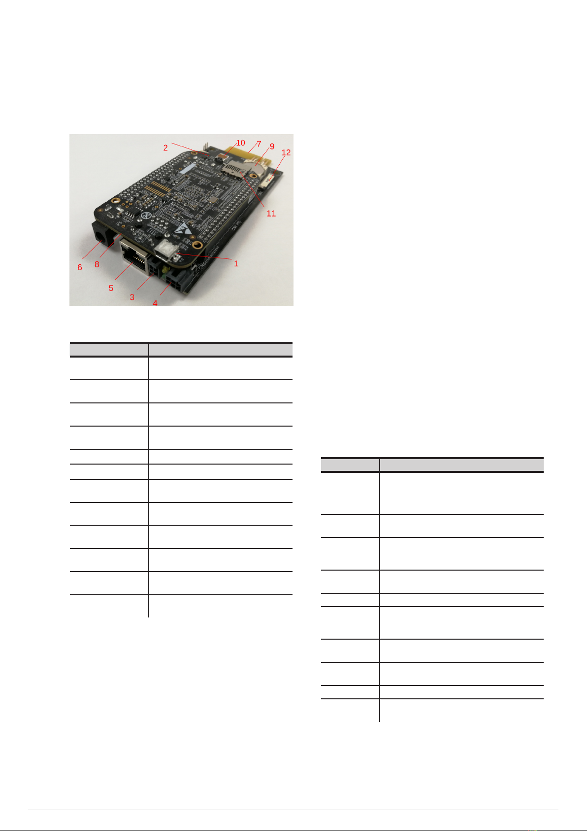
Fig. 1. View of the NIMBUS card
Description Function
1COM1 port Serial interface to connect the card to other
devices using a mini USB cable.
2COM2 port Serial interface to connect the card to other
devices using a USB cable.
3RS-232 port Serial interface to connect the card using the
RS-232 protocol.
4RS-485 port Serial interface to connect the card using the
RS-485 protocol.
5RJ-45 port 10/100Mbit Ethernet interface.
6External DC input Powered by a 5V adapter.
7Modbus port Serial interface for modbus communication
with the device. Powers the card internally.
8Power LEDs Turned on when the card is powered with the
DC input (internal or external).
9RTC Real-time clock to keep the time of the card
updated in case of mains failure.
10 HDMI port HDMI interface to connect the card using an
HDMI micro cable.
11 MicroSD connector Enables the NIMBUS card version to be
updated using a MicroSD.
12 Display connector Connector for flat bus cable to connect the card
to an LCD.
Tab. 1. Description of the constituent parts
1.2. DESCRIPTION OF THE SYSTEM
1.2.1. Introduction
The SALICRU devices are usually installed in locations far away
from the area of production, which means that information pro-
vided by the device about its status can often be overlooked.
The NIMBUS card solves this problem by offering a remote
maintenance service that provides real-time information about
the current status of the device.
Remote communication with the device enables maintenance
and repair work to be carried out without the need to travel to
the installation site to find out about its status.
The functionalities of the NIMBUS card are specially designed
to work with SALICRU devices, making it currently compatible
with the following series:
•DC POWER-S
•DC POWER-L
•SLS CUBE3 / CUBE3+
•SLC CUBE4
•EMI3
•SLC ADAPT/X
•SLC ADAPT2
•SLC X-PERT
1.2.2. Features of the system
The NIMBUS card features various basic integrated services to
enable basic connection to the device.
Basic service Description
Onboard panel Web panel that enables remote monitoring of the
device. As it is dependent on the NIMBUS card, if it
is not connected, it will not be possible to access the
panel.
Communication
through MODBUS
Reading data through MODBUS.
Communication
through MODBUS
TCP
Reading data through MODBUS TCP.
Communication
through SNMP
Reading data and reception of alarms through SNMP.
RTC The card’s internal real-time clock.
Auto-
configuration of
the device
When installing the card in any of the compatible
devices, it will automatically detect which device it is.
Alarm
notification
Notification alert through the onboard panel in real
time.
DNS server Possibility of assigning domain names to the device.
IP address Choice of DHCP or static web address.
RCCMD Enables remote shutdown of the designated clients
and servers under certain conditions.
Tab. 2. Basic integrated services