Salora XLE 8901 User manual

STEREO
.SATELLITE RECEIVER
XLE 8901
•BRUKSANVISNING
•OWNERS MANUAL
•BEDIENUNGSANLEITUNG
•BRUKSANVISNING
•MANUALE UTENTE
TECHNICAL SPECIFICATION
.!
I
J
1

-
Owners Manual
7
[

READ THIS FIRST!!
The owner's manualdoes notcoverthe installationof the parabolic antenna and its alignmentwith the satellite orbit
orthe satellite; it assumes thatthis work is complete. The owner's manual describes howto operatethe satellite
receiver.
It
is
in
two parts:
PART 1: INTRODUCTION -OPERATION -CONTROL FUNCTIONS
PART 2: CONNECTIONS -INSTALLATION -SETIINGAND ADJUSTMENT-TROUBLE
SHOOTING GUIDE-GLOSSARY
GUIDANCE
HOW
TO
OPERATEYOUR SATELLITE RECEIVER
XLE
with
antenna
motor
control
(Polar Mount).
1.
Basic adjustment (at the installation site)
pages
24
-26.
2.
Operation: "WATCHING SATELLITETV" (normal use)
page
8.
3.
Otheroperation (adjustment, satellite radio, parental lock)
pages
9 -
11.
4.
Setting (reprogramming)
pages
27
-
31.
XLE
without
antenna
motor
control
(fixed antenna
position)
1.
Polarizeradjustments,when polarizer
is
included (atthe installation)
page
25.
2.
Operation:" WATCHING SATELLITE TV" (normal use)
page
8.
3.
Otheroperation (adjustment, satellite radio, parental lock) pages9 -
11.
4.
Setting (reprogramming) pages
27
-
31.
GB-2

PART 1
GB-3

INTRODUCTION
Satellit TV reception........... 4
Satellit TV equipment............................... 5
Satellite receiver...................................... 6
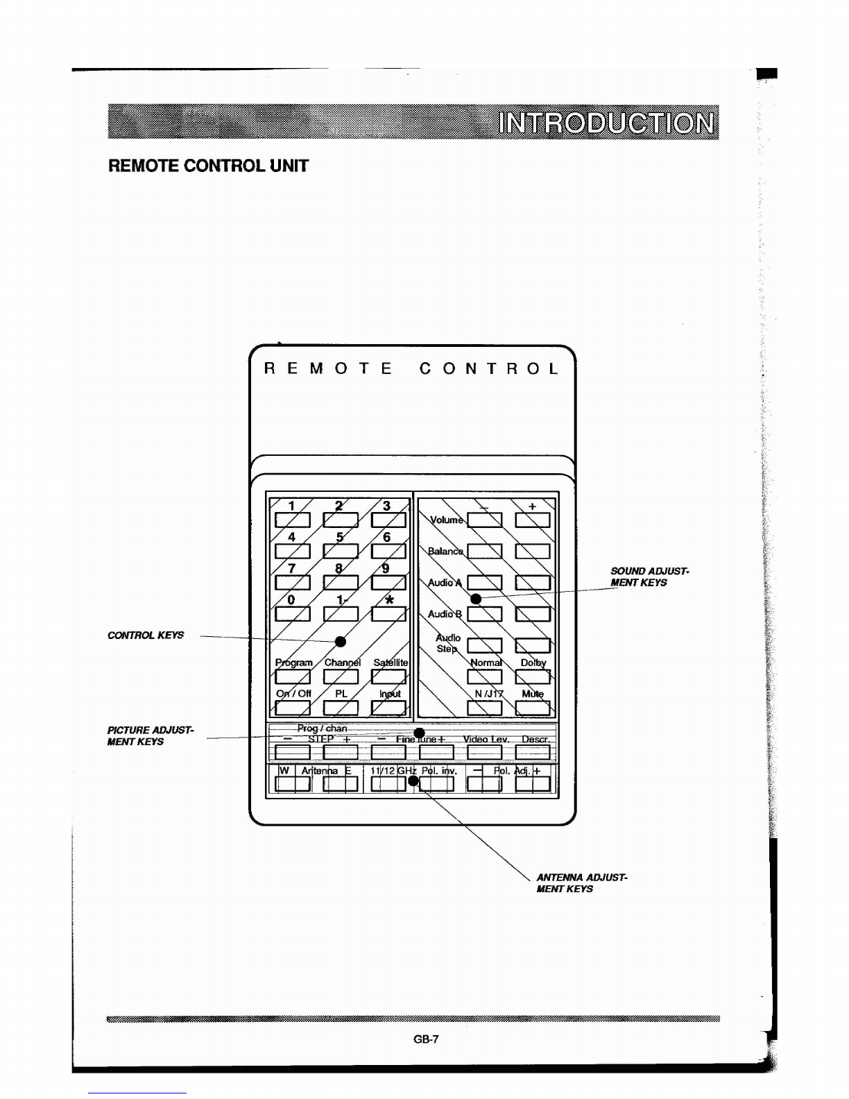
Remote control unit.................. 7
OPERATION
Watching satellite TV................................ 8
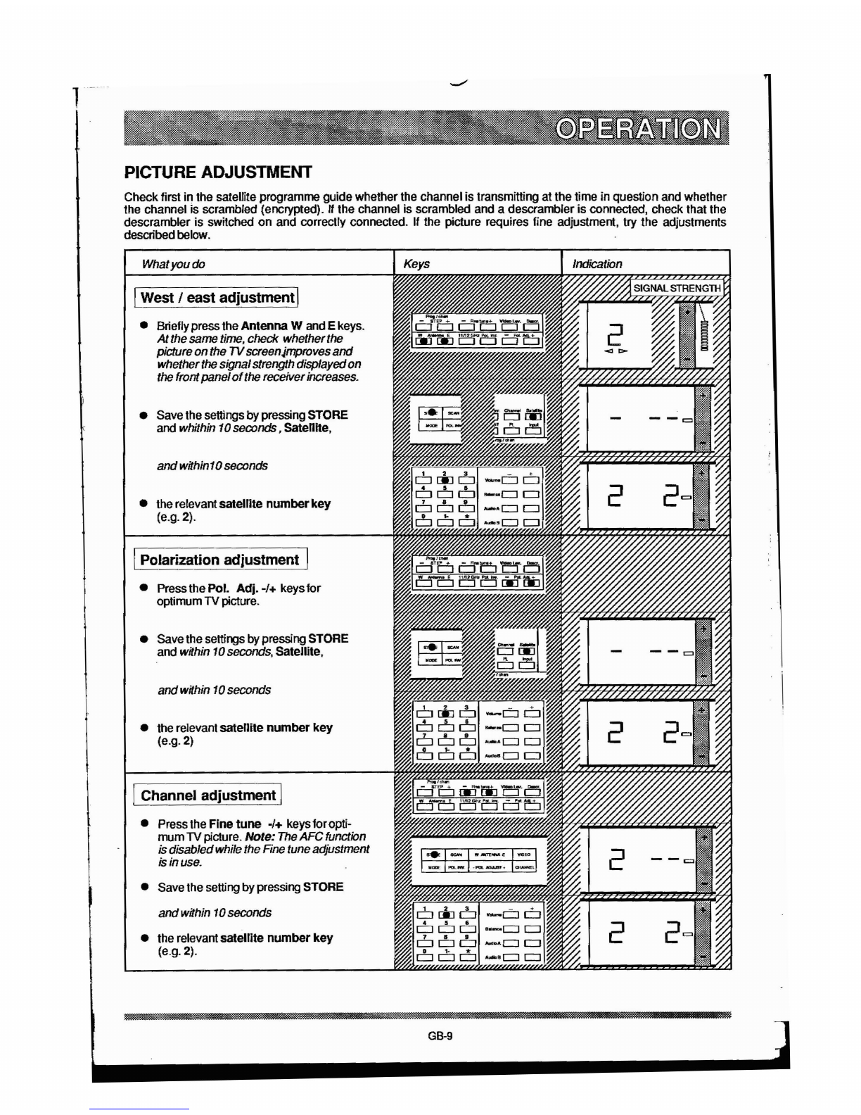
Picture adjustment..... 9
Sound adjustment................................. 10
Satellite radio.........................................
11
Parental lock.
11
CONTROL FUNCTIONS
Remote control unit................................
12
Satellite receiver...................................... 13
SATELLITE TV RECEPTION
To
many people, satellite TV reception is something
completely new and, in some ways, strange. Some pe-
ople find it complicated, whilst other people consider it
the most exiting event
in
television for many years.
Satellite reception is not complicated, although the
equipment required differs from the set you already
have for the reception of ordinary TV programmes. Pro-
bably the most striking feature is the parabolic antenna
or dish, which is quite different from aconventional TV
antenna. Indoors there will
be
an extra unit (two if you
have apowered antenna) alongside the video
and
the
TV
set.
General
High up
in
space above the equator there are many
satellites orbiting the earth in what is known as the geo-
stationary orbit: this means that they appear to hover
directly above the equator over agiven point. Some of
these satellites retransmit TV signals for reception on
earth. These signals are weak and are transmitted
at
a
very high frequency; they need aspecial parabolic
antenna to ensure that the transmitted TV signal can
be converted into
an
acceptable picture. The antenna
needs
to
be
of acertain size
and
must
be
accurate-
ly
aligned
on
(aimed at) the satellite
to
give a
picture ofgood quality.
Each TV satellitetransmits several programmes on sepa-
rate satellite channels.
To
make optimum use of the
available frequency spectrum without the signals inter-
fering with each other, they are transmitted with verti-
calor
horizontal polarization.
To
ensure agood
picture, the LNB (low-noise block converter) of the
satellite dish must
be
turned to suit the polarization
of
the required channel. There are two ways of switching
rapidly from one TV satellite channel to another: the
antenna can be fitted with two LNB's, one for each
polarization, or asingle LNB can be
Htted
with amotor-
driven polarization changer known
as
apolarizer.
In
the latter case the polarizer is controlled
by
the satellite
receiver to switch automatically to the correct polariza-
tion when asatellite channel is selected.
To receive TV signals from several
TV
satellites, the an-
tenna will need to
be
re-aligned. This can be done by
hand, although it is atroublesome and time-consuming
operation. The preferred method is to use
an
antenna
motor
that tums the dish to aim it exactly
at
the
desired
satellite.
Acomplete installation package for satellite
TV
recep-
tion consists ofthe following:
osatellite receiver. This unit picks upthe desired
TV channel from the signal arriving
at
the
LNB
in
the
antenna.
The
unit also generates control signals
to
select the correct satellite and polarization.
oantenna power drive
for
antenna
motor
and polarizer. This is aseparate unit. The anten-
na powerdrive communicates with the satellite
re-
ceivervia acable link.
oantenna
with
motor,
LNB and polarizer (or a
double
LNB,
known
as
an ortho modetransduceror
OMT).
About the manual
Parabolic antenna.
The
assembly and alignment
of
the parabolic antenna are described
in
separate in-
stallation instructions supplied with the equipment.
The
manual goes to considerable lengths to point out the
importance
of
careful assembly and alignment to en-
sure the best possible picture and minimize snow.
This
advice
is
particularly important for the installation
of
a
dish antenna with antenna motorand apolar mount.
Installation.
The
installation of adish antenna
with
motor and polarizer or ortho mode transducer involves
running and connecting several cables between the
antenna and the TV set.
It
is, in fact, afairly complicated
installation. Study the wiring diagram carefully and
double-check
to
make sure that all the wires
run
to the
correct connections. We
don't
want
to
harp on
the point,
but
if
an item
of
equipment
is
in-
correctly
connected and receives
too
much
power It
will
be
damaged.
The
section entitled SETTING AND ADJUST-
MENTS describes
in
detail the many steps involved
in
setting up adjusting the satellite receiver. There is
no
need to carry out all these steps when the equipment
is
installed; the main thing is to carry out the basic
operations. The rest of the instructions
in
the chapter
are used when the time comes to reprogram or to load
new programme informationinto the receiver.
GB-4

SATELLIT
TV
EQUIPMENT
REMOTE CONTROL UNIT
LNB
(LOW-NOISE BLOCK CONVERTER)
BRACKET
SA
TELLlTE
RECBVER
ANTENNA POWER DRIVE
POLAR
MOUNT
GB-5

SATELLITE RECEIVER
We
hope that the XLE satellite receiver will give
you
a
new outlook on television viewing.
You
will have afar
greater choice of TV programmes when you can scan
through agenerous range of progranvnes without
stopping until you see something really interesting. It is
agood idea to have asatellite programme guide handy
to helpyoufind yourway aroundthe satellitechannels.
To make things aseasy as possible for you, the installer
and
user, when you receive your XLE satellite receiver,
it is already programmed for several satellite channels.
What you will have to program
is
the alignment of the
antenna on different satellites, whether it is amotor-
driven antenna, and the setting of the polarizer, if there
is one. "the antenna is aligned manually (to fixed
positions) instead of by amotor, all you have to do is
select the
satelUte
(the one on which the antenna is
aligned) and the programme
as
shown in the satellite
programme guide supplied with the satellite receiver. "
apolarizer is included, it must
be
set correctly first. A
table in the guide shows how the receiver has been
preprogrammed.
In
al"
some 60 satelflte channels (some of which
are
radio channels) distributed via
six
satellites are
preprogrammed in XLE, butthe receiver has even
more
memory space: the positions of upto nine satellites
can
be programmed in, and there is achoice of 16
programmes for each satellite position
(9
x
16
satellite
channels). An explanatory programming model for
XLE
is shown
on
page 23.
When the satellite receiver is ready for use,
Le.
when it
is set up in accordance with the SETTING AND
ADJUSTMENTS section in the ONners Manual, the
simplest way to control it is to use the remote control
unit. Many of the functions on the remote control unit
arealso available onthe receiveritse" (most of them are
concealed behind the front panel); see the diagrams
below and the detailed description of the receiver on
page 13. The illustration on the next page shows the
lauout of the function keys. There is adetailed
descriptionofthe remotecontrol
urit
on page
12.
/"
~+
/
/
FLAP
/
/
~
--
..
..
IIETEJl
AWWT
GB-6
\
I
~
....
I
....,
I •_
.....
E
I"DEO
I
I
"DE
I
PIlL.;,.
[.
PIlLADJ.....
[..-1
\\

REMOTE CONTROL UNIT
J!II
REMOTE
CONTROL
KEYS
PICTURE ADJUST-
MENTKEYS
CONTROL
SOUNDADJUST·
MENTKEYS
ANTENNA ADJUST·
IfENTKEYS
GB-7

WATCHING SATELLITE
TV
What
youdo
11.
Starting I
•Switch
on
the
switches
at
the
rear
of
the
satellite receiver
and
antenna powerdrive.
•PressPOWERor
On
JOff
to
switchon
the
units.
12.
select satellite I
•
Press
Satellite.
•
Wrthin
10
seconds, select satellite
number,
(e.g.
2=
Intelsat5).
The
antenna
turns automatically
to
Intelsat
5.
l3.
select programme I
•
Press
the required key
(e.g.
2)
Check
in
the satelliteprogrammeguide
which
satellitechannelisstoredunder
the
relevantprogramme
number.
For
two-oJgit
numbers, firstpress
1-
followed
by
the
second
digit.
•
You
can alsoselectprogrammes
by
pressing the steppingkeys.
'4.
Switching
off
I
•Ifthe receiver
is
switched offwith the
POWER or
On
JOff
keys,
it
goes into
standbymode.
•
To
switchoff
the
satellite receiver
and
antennapowerdrivecompletely.
use
the
switcheson
the
rearofthe units.
GB-8
.1
I
k

1
PICTURE ADJUSTMENT
Checkfirst in the satellite programme guide whether the channel is transmitting at the time in question and whether
the channel is scrambled (encrypted).
If
the channel is scrambled and adescrambler is connected, check that the
descrambler is switched
on
and correctly connected. If the picture requires fine adjustment, try the adjustments
describedbelow.
What
you
do
IWest Ieast adjustmentI
•Brieflypressthe
Antenna
Wand Ekeys.
Atthe
same
time,
check whetherthe
pictureonthe
TV
screenjmprovesand
whether
the
signalstrength displayedon
the
frontpanel
of
the
receiverincreases.
•Save the settingsbypressing STORE
and whithin
10
seconds, Satellhe,
and
within
10
seconds
•therelevant
satellite
number
key
(e.g. 2).
IPolarization adjustment I
•PressthePol.
Adj.
-/+ keys
for
optimum
TV
picture.
•Savethesettings bypressingSTORE
and within
10
seconds,
Satellite,
andwithin
10
seconds
•the relevant
satellite
number
key
(e.g. 2)
IChannel adjustmentI
•Press the Fine tune -/+ keysforopti-
mum
TV
picture. Note:
The
AFCfunction
isdisabledwhile the
Fine
tuneadjustment
is
in
use.
•Save the settingby pressing STORE
and
within
10
seconds
•the relevant
satellite
number
key
(e.g. 2).
GB-9

f
SOUND ADJUSTMENT
Volume
and
stereo balance
can
be preset
to
suit your preference
and
the settings
can
be
saved.
If
you
make
a
temporary
change
with the
volumeJbalance
keys,
all
you
have
to
do
is
to
press the Nonnal key
to
restore
the
original settings.
Whatyou do
(volume (stereo) I
•Setthe volume withthe Volume -/+
keys.
This appliesonlyto
$peakers-
and
line outputsfor
stereo.
Note!
mono
and
RF outputs
have
afixed
sound
level.
"the
soundis connected
to
an
amplifier,
the
volume mayonly
be
adjusted
with
the
volume
control
of
the
amplifier. Otherwise,
the
amplifierinputstage canbe over-
driven.
IBalance (stereo)I
•
Use
the
Balance
keys
to
selthe
sound
balance between left
and
rightloud-
speakers.
ISave as normal settingsI
•
Press
STORE
andwithin
10
seconds,
•press Normal.
IDolby
NR
(Noise reduction)I
•
Press
Dolbyto selectthe Dolbyfunction.
Press
againtodeselectthe
Dolby
function.
•
Press
Mute
10
silence
lhe
sound.
Press
again
to restore
the
sound.
GB-10

SATELLITE RADIO
The
settings
10r
several radio programmes are stored in
the
satellite receiver; these include Voice
01
America, which
istransmitted via Eutelsat
1.
Seethe satellite programmeguidefor otherradio programmes.
Whatyou
do
IVoice
of
America (Eutelsat 1) I
•Press
satellfte
andwithin
10
seconds
press
key
1to select Eutelsat
1.
•select programme 10.
PARENTAL
LOCK
One or more programme
nurmers
can
be
locked with the
PL
function in the receiver. All controls
on
the
front panel
are then locked except for
programme
stepping
and the POWER key; the receiver is also locked to one
satellite. The remotecontrol unitisthe key, and musttherefore
be
putawayafterprogrammelocking.
Whatyoudo
•Selectasatellite
with
programmesyou
wish
to
lock..
•Selectaprogramme
nurmer
on
which
you wanttopreventviewing.
•Pressthe
PL
key.
•Repeatthe aboveprocedure foreachpro-
grammenumberforwhichyou want
to
pre-
vent
viewing.
Putawaythe remote control
unit.
IUnlock]
•Selectalockedprogramme
nurmerwith
theremote control unit.
The
frontpanel
displaystillshowsPL.
•Pressthe
PL
key.
•Repeatthe aboveprocedureforeach
programmenumberthatyou wantto
unlock.
G8-11

REMOTE CONTROL
UNIT
REMOTE
CONTROL
1 2 3 +
CJ CJ
CJ
4 5 6
CJ
c=J
c=J
..
.-------+--1
7 8 9
CJ
c=J
c:::J
o
1-
*
CJ
CJ
c:::J
.-----+-~---
0NUMBER
SELECllON
KEYS. Usedto selectpro- •
POL
ADJ.
-/
+.
Forfine adjustment ofthe
gramme, channel, satellite position or mode numbers. polarizersetting.
•SATELLITE. Puts the receiver in satellite modefor e
DESCR
Toselectachannel that goes viaa
programming
or
satellite selection. connected descramblerunit.
eCHANNEL. Putsthe receiver
in
channel mode for
CD
VIDEO LEV. Increases
and
decreasesthe video
channel selection. level.
0PROGRAM. Putsthe receiver
in
program modefor •FINE TUNE -I
+.
Forfine tuning ofthe picture.
programme selection (normal mode).
CD
•MUTE. Silence the sound. Pressing the key again
PL. Programme lockfunction to preventthe selection restores the sound.
ofcertain programmes. Programme
lock
also prevents
..
the antennafrom being turned by means ofthe keys NI
J17.
Selects narrow-band
(NS)
orbroad-band
on thefrontpanelof the satellite receiver. sound with de-emphasis J17or 62
us.
e
ON
IOFF.
WOn-
afterthe switch on the rear ofthe •DOLBY. Dolby NR noise reduction.
satellite receiverhasbeen switched on. After"Off- the
G)
receivergoestostandby mode.
NORMAL
Restores preset sound volume and
•balance.
INPUT. To select RF input 1or 2on the receiver. If •
input2
is
selected, IN-2 appears
on
the displayon the AUDIO STEP. To select audio system.
front panel.
..
•AUDIO B. Setting of sound frequency tothe stereo
PROG
I.
CHAN -STEP
-/
+.
Forstepping up and systems (leftchannel). The frequency
is
displayed
by
downthrough programmes and channels. the programme/channel display. i
0eI
ANTENNA WI
E.
Turns the antennatowards the AUDIO
A.
Setting ofthe sound frequency for mono l
west(W) oreast{E). systems and the right channel ofstereo systems. The t
frequency
is
displayed
by
the programme/channel
G)
11/12
GHz.
Toselecta12GHzsystem,
if
display.
installed. •BALANCE. Used duringstereo reception to ,
.-
POL
INY. Changes the setting ofthe polarizerfrom balancethe sound ofthe left
and
right channels.
vertical to horizontal orfrom horizontal tovertical. •VOLUME.
G8-12

SATELLITE RECEIVER
•POWER. On/off. "On" afterthe switch on the rear of •DOLBY. Dolby
NR
noise reduction.
the satellite receiver has been switchedon.After 'Off" G
the receivergoes
to
standby mode. AUDIO BANDWIDTH. NB =narrowband; when
NB
eis notlit, broadband.
IR
SENSOR. Infrared
sensorto
~eceive
signalsfrom •
the remote control unit.
DE·
EMPHASIS. Sound correction.
J17
when
fa
indicated, otherwise 62us.
WEST/EAST
INDICAllON.
Blinkwhenthe e
antenna isturning towardsthewest (left LED)
or
AUDIO
STEPPING +1-.
To
selectaudio system.
towards theeast (right LED).
..
•
SIGNAL
LEVEL.
Displays relative
stren.
of
MODE
INDICA
l1ON.
Litwhenthesatellite receiver incomming signal. Can
be
adjusted with
is
setto
MODE.
G)
G)
TEST. Testfunction. (See page. 32)
SA
TELUTE
INDICA
llON.
Anumeral (1-9) •
indicates which satellitetheantenna is aimed at. INSTRUMENTADJUSTMENT. To adjust signal
G>
ACllVE.
Alwaysblinks when akey
on
thefront level indication
CD
(see
page 18).
panel
or
onthe remote control unit
is
pressed. 0AFC.
AFC
adjustmentforoptimum picture quality
..
(see page 18).
PROGRAM
1
CHANNEL
/
AUDIO
INDICAllON.
G
Displays selected programme/channel number
or
VIDEO. Fine adjustment
of
the video level.
audiofrequency.
CD
..
STORE. Storesthe settingsthat have been made.
CHANNEL
INDICAllON.
Lit when the satellite
G)
receiver is
in
channel mode. MODE. Used for preliminary settingsofthe antenna.
eINPUT INDICATION. Displays IN-2when input 2
I)
SCAN. Starts!stops automaticchannelscanning.
has been selected with the input keyon the remote
8)
control unit. POL. INY. Changes the setting of the polarizerfrom
..
vertical
to
horizontal orfrom horizontal
to
vertical.
POLARlZAllON
INDICATION 1
VERTlCAL
I)
Lit whenavertically polarized channel
has
been
ANTENNA
W1E. Turnsthe antennatowardsthe
selected. west (W)
or
east (E).
•
POLARIZAllON
INDICATION /
HORlZONTAL
'9
POL
ADJUST
-I
+.
Forfine
adjustment ofthe
lit
when ahorizontallypolarized channel hasbeen polarizer setting.
selected.
ED
VIDEO. Same function as
41)
.
•
CHANNEL
STEPPING +I
-.
Steps programs!
tD
channels
up
(+)
or
down(-).
CHANNEL.
Putsthe receiver in channel
modefor
Gchannel selection.
AUDIO
AlB.
Indicateswhich sound channel
(A
orB) •
has been selected. VIDEO
LEVEL
AND
11/12
GHz
INDICATION
•The dot lights
up
lor
asecond
or
iWhen
the video
AUDIO
INDICAllON.
Indicates which type of audio level israised with VIDEO LEV.
The
dlSO
system
is
in
use:
MONO
or STEREO. When STEREO lights up on 11/12
GHz
switching
With
key •when
has been selected,
STEREO
is lit on the front panel. the
11
GHz
system is selected. See page 21.

1
K>
1
31
PART 2
GB-15
_________
.~.
-
~_~_.~-_-
.....
-
~-_~-.-
_iliiiliiiii3

CONNECTIONS
Antennapowerdrive..............................
16
Satellite receiver..
17
INSTALLATION
Hints
on
installation................ 18
Basicsystem..
19
Dual LNB (ortOO).................................... 20
Signal alT1JliflCation................................. 20
Signalsplitting... 20
Dual
systems
(fixed)...............................
21
Video recorderIextraloudspeakers........
21
Stereo...................................................
21
SETTING AND ADJUSTMENT
Introduction........................................... 22
Programming modeL............................ 23
Basicadjustment........
24
-
26
Programmes...
27
-
28
Soundfrequency...................................
28
Satellite descrambler.
29
Dual systemprogramming.................. 29 -
31
TROUBLESHOOTINGGUIDE
Testfunclion......................................... 32
Trouble/Cause/Remedy.......... 32-33
GLOSSARy.................................................... 34
ANTENNA
POWER
DRIVE
MOTOR POWER.Antenna motorconnections.
POLARIZER. Polarizerconnections.
GROUND~RTHSCREW
CONTROL INPUT.Forconnecting lead
to
satellite
receiver.
FUSE. Antenna motorfuse. 3.15 AT.
POWER. Mains switch.
220
V.
Mains connection.
GB-16

>
..
!1.
SA
TELllTE
RECEIVER
CD
RF-INPUT 1. Connection for satellite signal cable
..
from LNB. Thesame cable is also used to supply
11
I12. Control voltageforswitching between
11
powertothe LNB. The voltage can beeither 18 or 15V and 12GHz systems.
to
controlthe polarizer. fa
.f
(I
RF-INPUT 2. Same as
CD
MONO. Mono sound outputforconnection to
TV
monitor, video recorder
or
amplifier.
•VIDEO OUTPUT: NORM. Forconnecting leadto fa SPEAKER: RIGND. Loudspeakeroutput, right
TV
monitoror video recorder. channel.
•VIDEO
OUTPlIT:
DESCRAMBLER. For fa
SPEAKER:
L / GND.
loudspeaker
output, left
connecting lead
to
descrambler unitwhen receiving channel.
scrambled (encrypted) programmes. •
(I
ANTENNA
DRIVE. Forconnecting lead to antenna
VlDEOPOLARITY: INV. /NORM. powerdrive.
Switch
to
invertthe video signal. •TEST. Testoutput
to
checksignal level. Avoltmeter
~
..
RF
OUT. Forconnection
to
the antenna Inputofthe set
to
DCis connected to TESTand
GND
(ground/
TV
receiver. earth) to measurethe
AGC
voltage that is used when
•adjusting the antennadish. For agoodpicture, the
TV-ANT. IN. Connectionfor
TV
antenna. voltyage must
be
between 2.0and 6.5V.
fD
TEST. Facility
to
assist
in
settingthe channel •POLARIZER: PULSE. To connect pulse signal
selector
of
the
TV
receiverto theoutputchannel of lead
to
the polarizer.
the
satellite receiver. •
•POLARIZER: 5V. Toconnect
the
5 V lead
to
the
CHANNEL
30 -39. RFchannel setting. Any polarizer.
channelfrom 30to
39
may beselected. Setto channel •
33
atthefactory. POLARIZER: GND. Polarizerground/earth
•connection.
VIDEO /AUDIO IN. Inputforvideo/audio signal •
from descrambler, video recorder
or
other external
ON
/OFF. Mains switch.
video suorce and connection forfast programmer. •
..
GROUNDIEARTH
SCREW
R • LStereo outputs
for
sound signalsforconnec-
(I
tionto
TV
monitor, video recorderorstereo amplifier.
MAINS
CONNECnON:
220V
/50
Hz
GB-17

DIL& ;.
HINTS ON INSTALLATION
Use screened cables
When installing the satellite receiver, refer to the
connection examples on pages 19-21. Please read the
following advice before starting.
Connecting the motor and polarizer
II,
instead
of
using special cables, you use separate
cables for the antenna motor and polarizer, make the
connectionsasfollows:
On the rear panel of the satellite receiver there
is
atest
terminal (TEST). A
DC
voltmeter can be connected
between TEST and GND (ground/earth) to measure the
AGC voltage when adjusting the antenna. The voltage
must be between 2.0 and 6.5
V.
The antenna setting is
optimalwhenthe test voltage is lowest.
Signal strength meter
On the satellite receiver there is an instrument to
indicate the signal strength. The meter can be adjusted
with potentiometers (45) behind the front panel of the
satellite receiver.
II the antenna has two LNBs with an ortho mode
transducer, the LNB with vertical polarization may be
connected to input
1,
for example, and the horizontally
polarized LNB to input
2.
The receiver is not
preprogrammed for this arrangement; see SETTING
AND ADJUSTMENT, page 31.
Test terminal
Setting the channel selector
of
tlie
1V.
If the satellite receiver is connected to the antenna
input of the TV, the channel selectorof the TV must be
adjusted for the output channel of the satellite receiver.
To make it easy to find the right channel with the
channel selector the satellite receiver has abuilt-in
TEST function, which gives atest image (black and
white bars) when the channel is correctly set. Set the
switch to TEST during the adjustment and to the other
settingwhenthechannel selectortheTV hasbeen set.
3-CORE
CABLE
FOR POLARIZER
EARTHlGROUND
SCREW
FOR
CABLE
SCREEN
POLARIZER
~
PULSE
.SIIl,5A
7'
//
//
//
/
MOTOIf'OWER
BG"-Il
PULSE
A
Use screened cables to connect the polarizer and
antenna motor if the distance between the antenna and
the satellite receiver
are
more than 50
m.
Make sure that
one end (not both) of the screen braid is connected to
the ground/earth screw at the antenna powerdrive or
at
the satellite receiver. See basic connection diagram on
next page. You do
n't
need to connect to aground
point atthe antenna.
S-CORE
CABLE
FOR
ANTENNA MOTOR
A. Selectasatellitechannel with alowchannel
numberand adjust the AFC potentiometer(46)
forbest picture.
AFC
adjustment
If
there is alot of black
or
white "snow" on the picture,
the AFC may be wrongly adjusted. Check whether the
picture can be improved with the Fine tune keys on the
remote control unit.
II
so, the AFC needs adjusting;
proceedasfollows:
Polarizer Iantenna motor
Before fitting the polarizer and antenna motor to the
antenna, check first indoors that they work properly in
conjunction with the satellite receiver and antenna
power drive. See the separate instructions "Installation
preparations"supplied withthe satellite receiver.
RF-Input
(1
and
2)
Be sure to connect the cable from the LNB to the cor-
rect input. If this connection
is
wrongly made, the pre-
programming of the receiver may turn out to be in-
correct when you come to select satellite programmes.
This means that you must check in the satellite
programme·guide that you have connected the cable
Irom the LNB to the input that is preprogrammed for the
satellite orsatellites onwhich yourantenna
is
aligned.
B.
c.
Select asatellite channel with ahigh channel
numberand checkthe picture.
Ifyou cannotgetagoodpicture on both high
and low channel numbers, checkoobles and
connectors.
GB-18

BLACK
POlARIZER
PULSE.
+510,5
II.
WHITE
GREY
o
....
0
CONNECT
CABLE
SCREENS
TO
GROUNll'EARTH
SCREW
--Tr
I I I
I I I
I I I
MOTOIt'OVIIER
A B
ON>
PU.SE
BLACK
THE
DIAGRAM INTHE BOXABOVE
SHOWS SCHEMATICALLYHOW TO
MAKE THE CONNECnoNS BETWEEN
ANTENNA. TERMINAL BLOCK AND
ANTENNA POWER
DRIVE.
THE
COLOURS
OF
THE
WIRES
APPLY
BOTH FOR
THE
RIBBON CABLEAND
FOR
THE
WIRES
FROM
THE
ANTENNA
AIOTOR
AND POLARIZER. IF
THE
CAB-
LES
ARE
WRONGLY
CONNECTED,
EXPENSWE DAMAGEMAY
BE
DONE.
WHEN
QlECKNG
THE
SIGNAL
STRENGTH,
CONNECT
A
VOLTMETER
(DC)
BETWEEN
THESE
POINTS.
FOR
GOOD
SIGNAL
STRENGTH
(GOOD
PICWRE)
THE
VOLTMETER
READING
MUST
BE
BETWEEN
2.0
AND
6.5
V.
THE
LOWER
THE
BETTER.
7-WAY DIN
CABlE,
SUPPUEDWffil81llll
AlDlO/VlDEO
CONNECTONTO
TVSCART
CONNECTOR
I
~WAY
I
RIB80H
CABLE
12
GHz
SYSTEM
WITH
POLARIZER
;,
/\
'J:i:r/ ,
r-
Jl
:,
J
II
\\
,
I
I~'
I -
II
IL _
I
I
I
NORMAL
CONNECTlON
TO
ANTENNA
INPUT
I .
~Tt]
01
IBASIC SYSTEM I

IDUAL
LNB
(ORTHO) I
HORIZONTAL LNB
WHEN
AN
ORTHO
MODE
TRANSDUCER
WITH
TWO
LNB's
IS
USED.
CONNECT
THE
VERTICAL
LNB
TO
INPUT
1
AND
THE
HORIZONTAL
LNB
TO
INPUT
2.
VERTICAL LNB
1SIGNAL AMPLIFICATION
UNEDRIVER
(Jtl
tnn-i-----~
__
~I----,
IN
SONE
INSTAlLATIONS.
THE
SGNAL.
LEVEL
MAY
BE
WEAK
NORMALLY
THIS
WLl
OCOJR
WHEN
THE
ANTENNA
AND
THE
SATELLITE
1V
RECEIVER
ARE
TOO
FAR
APART.
IT
MAY
ALSO
ARISE
WHEN
SEVERAL
RECEIVERS
ARE
CONNECTED
m
THE
SAME
LNB
AND
THE
SGNAL
IS
SPLIT.
AS
SHOWN
IN
THE
DIAGRAM
BElOW.
TO
MAlNrAIN
THE SIGNAL
AT
SUFRaENT
STRENGTH, A
I.JNE
DRrVER (AMPURE1l)
CAN
BE
CONNECTED IN
TIE
CABLE. YOU
MU
NORIlAUY
NEED
TO
USE
A
UNE
DRrIBl
WHEN
UORE
THAN 30
"OF
RG
"U
CABLE
ARE
USED.
IF
YOU USE
RG
n3U
CABu;.
YOU
WlU
BE
ABLE
TO
RUN THE
CABLE
FROM
TIE
ANTENNA ATALEHU1H
OF
UP
TO
5011 WfTHOUT NEEDING A
LlNEDRVER.
1El.
4-WAY
SPUTTER
1
HORIZONTAL
4-WAYSPUTTER
USIIIG SGNAL
SPLITTERS
THAT
CAN
HANDLE
SGNALS
AT
FREQUENCIES
AS
HIGH
AS
1
GHz
WIll
AlLOW
YOU
TO
SPLIT
Tf£
SIGNAL.
FROM
A
SINGLE
ANTENNA
AND
FEED
ITTO
SEVERAL
SATELLITE
RECEIVERS.
THE
EXAMPLE
I-£FE
SHOWS
HOW
TWO
SGNALS
(VERTICAL
AND
HORIZONTAL
POLARIZATION)
CAN
BE
SPlIT
USING
TW04-WAY
SPLITTERS
AND
FED
TO
FOUR
SATElliTE
RECEIVERS.
ISIGNAL
Sp(mING
I
GB-20
Table of contents
Other Salora Receiver manuals