Blankom IRD-6100 User manual

BLANKOM IRD-6100 HD IRD
User Manual

------------------------------------------------------------------------User Manual and Datasheet IRD-6100 Family
BLANKOM_IRD-6100_User_Manual_RR-V1.1-03-2018.doc - 2 -
Table of Content
Chapter 1 Product Outline........................................................................................................ 4
Outline .................................................................................................................................... 4
Application Example ................................................................................................................ 5
Features .................................................................................................................................. 6
Block diagram.......................................................................................................................... 6
Specifications:.......................................................................................................................... 7
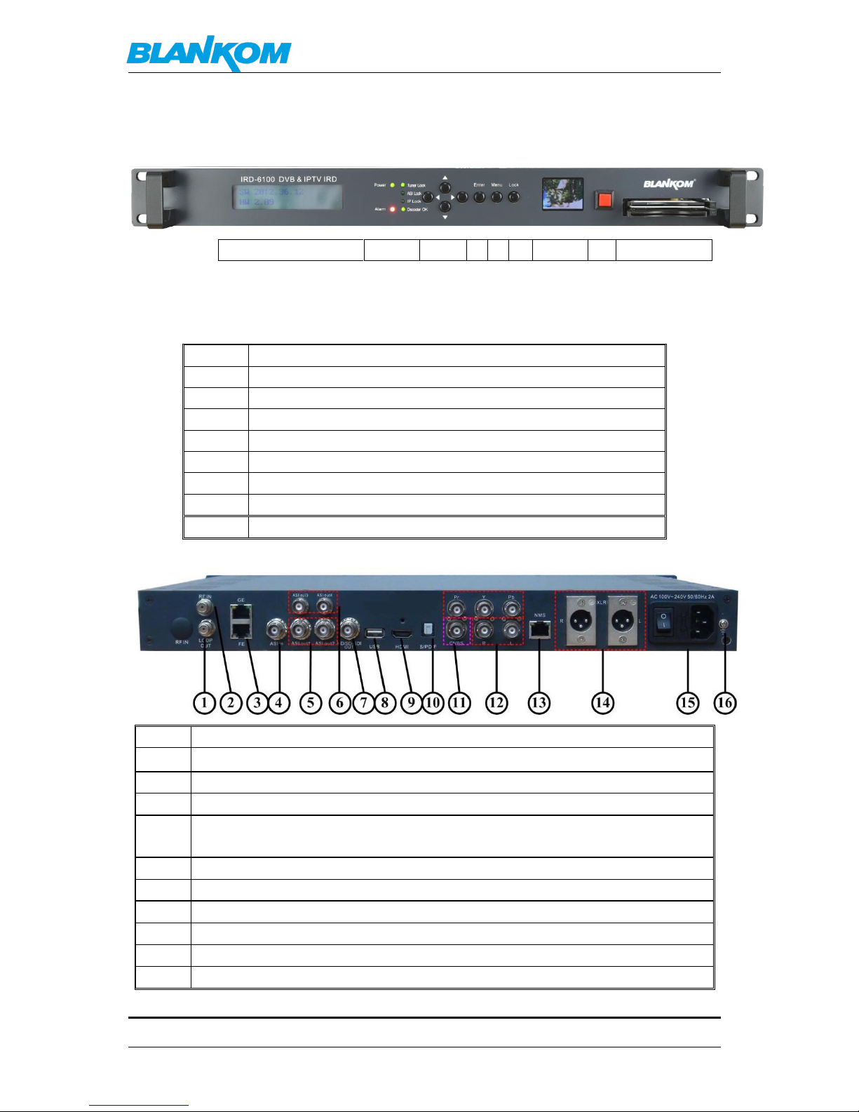
Appearance and description..................................................................................................... 8
Chapter 2 Installation Guide..................................................................................................... 9
Accessories.............................................................................................................................. 9
Installation Preparation ........................................................................................................... 9
Environment Requirement ....................................................................................................... 9
Grounding Requirement......................................................................................................... 10
Wire Connection.................................................................................................................... 10
Signal Cable Connection ......................................................................................................... 11
IRD-6100 HD IRD Satellite Receiver Signal Cable Connections:................................................. 11
Chapter 3 Operation .............................................................................................................. 13
Keypad Function Description:................................................................................................. 13
Main Interface ....................................................................................................................... 14
General Setting...................................................................................................................... 14
Input Setting.......................................................................................................................... 14
Tuner In................................................................................................................................. 14
ASI IN .................................................................................................................................... 15
IP IN ...................................................................................................................................... 15
Output Setting ....................................................................................................................... 16
Multiplex Setting ................................................................................................................... 16
Output Bit rate ...................................................................................................................... 16
Transportstream ID................................................................................................................ 17
Original Network ID ............................................................................................................... 17
IP Output............................................................................................................................... 17
Decoder Setting ..................................................................................................................... 17
Video Setting ......................................................................................................................... 18
Audio Setting......................................................................................................................... 18
Program Selecting.................................................................................................................. 19
Searching............................................................................................................................... 19
Decoder Selecting .................................................................................................................. 19
Descramble Setting................................................................................................................ 20
Card Setting........................................................................................................................... 20
BISS....................................................................................................................................... 20
Network Setting..................................................................................................................... 20
IP Address.............................................................................................................................. 20
Subnet Mask.......................................................................................................................... 20
Gateway................................................................................................................................ 21

------------------------------------------------------------------------User Manual and Datasheet IRD-6100 Family
BLANKOM_IRD-6100_User_Manual_RR-V1.1-03-2018.doc - 3 -
MAC Address ......................................................................................................................... 21
Service IP............................................................................................................................... 21
SPTS Net Configuration .......................................................................................................... 21
SPTS Configuration................................................................................................................. 21
SPTS IP Address ..................................................................................................................... 21
SPTS Gateway........................................................................................................................ 22
SPTS Enable ........................................................................................................................... 22
SPTS Parse Program ............................................................................................................... 22
Saving Configuration.............................................................................................................. 22
Loading Configuration............................................................................................................ 22
Version.................................................................................................................................. 22
Chapter 4 Web Browser configuration.................................................................................... 23
We recommend to use the latest Firefox browser on your PC/Laptop for this operation.......... 23
Login Interface....................................................................................................................... 23
Main Interface ....................................................................................................................... 23
System config: ....................................................................................................................... 25
General Settings for the DECODER & Output values: ............................................................... 26
MPTS-Output:........................................................................................................................ 29
MUX-Mode:........................................................................................................................... 30
SPTS-Outputs:........................................................................................................................ 32
Transmit:............................................................................................................................... 34
Now we crosscheck what we are getting out of the box: ......................................................... 34
BISS Descrambling (Basic Interoperable Scrambling System) ................................................... 37
Mode 1.................................................................................................................................. 38
Mode E.................................................................................................................................. 38
Mode E (Buried Key option unselected).................................................................................. 39
Mode E (Buried Key option selected)...................................................................................... 39
Chapter 5 Troubleshooting..................................................................................................... 39
Chapter 6 Packing List ............................................................................................................ 40
General notes about Streams: ................................................................................................ 41
Multicast streams: ................................................................................................................. 41
Registered port...................................................................................................................... 42
Range for Ephemeral port ...................................................................................................... 43
Packet structure..................................................................................................................... 43
RTP:....................................................................................................................................... 44
Note: Regarding SAP (Session Announcement Protocol).......................................................... 45
Contact:................................................................................................................................. 45

BLANKOM IRD-6100 HD IRD User Manual
BLANKOM_IRD-6100_User_Manual_RR-V1.1-03-2018.doc - 4 -
Chapter 1 Product Outline
Outline
This BLANKOM IRD-6100 HD IRD receives Transponder RF-signals from the installed tuner
(DVB-S/S2 /C/ T/T2 /ISDB-T/ATSC optional), ASI and IP-Input sources and multiplexed signals out to
ASI, IP as well as various video/audio interface outputs at the same time after multiplexing and
de-encryption with a CA module. It is featured with a LCD video monitor on the front panel. Its
video/audio outputs support professional HD/SD-SDI, YPbPr, HDMI, XLR balanced audio, and S/PDIF
digital audio as well as CVBS. With the CAM slot (CI/CI+) support, The BLANKOM IRD-6100 HD IRD
can support one channel (Tuner, ASI or IP) de-scrambling and output a transparent signal. The user
can operate the device with the front panel keypad or by Web-Interface based. Additional, the user
can choose to use an optional ASI output interface which can pass through the Frontend Input TS
directly. Optional available with modules for DVB-T/2 SFN network 10MHz Sync / MIP.
Statement:
Text and pictures herein are subject to changes w/o notifications.
The user manual will be updated in real time without special notice.
This user manual is provided only as a reference guide for technicians as examples.
Default Values
The factory default administrator account: admin
The factory-default user password: admin
The factory default IP address: 192.168.0.136 NM 255.255.255 GW 192.168.0.1
Set the administrator’s computer IP as: 192.168.0.* to avoid IP conflicting with the units own IP address
192.168.0.136.
192.168.0.*: use an IP setting “*” in the number range 2-254 and except the units default IP.
Remark: .0 is often the network router, .1 often the Gateway of the used router, .255 might be a network
broadcasting address.
Please change these account settings according to your local policy and network. -> Do not forget to safe and
backup the configuration by Web-Interface and its related system-sub-menu.

BLANKOM IRD-6100 HD IRD User Manual
BLANKOM_IRD-6100_User_Manual_RR-V1.1-03-2018.doc - 5 -
Application Example
Of course, instead of the HDMI-Encoder a usage of the HD-SDI-encoder SDE-264/265 is possible
too. IP MPTS Inputs can be used as well as ASI-Inputs to multiplex a new MPTS output from
different sources.

BLANKOM IRD-6100 HD IRD User Manual
BLANKOM_IRD-6100_User_Manual_RR-V1.1-03-2018.doc - 6 -
Features
Available Frontends: DVB-C/DVB-S/S2 DMB-T/DVB-T/ISDB-T/ATSC-T external RF Input (T2 under
development –please ask)
Various tuner versions available with RF demodulation range:
1) DVB-C: 47 MHz...860 MHz, 16/32/64/128/256 QAM
2) DVB-S: 950 MHz...2150 MHz, symbol rate: 2...45Mbauds
3) DVB-S2: 950 MHz...2150 MHz, symbol rate: QPSK 1...45Mbauds, 8PSK 2...30Mbauds
4) DMB-T: 146MHz ...862 MHz, 6/7/8 MHz bandwidth
5) DVB-T: 146MHz ...862 MHz, 6/7/8 MHz bandwidth
6) ISDB-T: 153 MHz ...862 MHz, 6/7/8 MHz bandwidth
7) ATSC-T: 54MHz...858MHz, 6MHz bandwidth
Extra LCD display for control of the selected decoded life video
Supporting MPEG-2 & MPEG-4 video decoding
Re-multiplexer embedded
Tuner, IP, ASI Input at the same time
IP, ASI, Decoding output at the same time
CAM card insert (CI/CI+)
Front Panel Keypad and Web-based NMS and SNMP network management
10x SPTS / 32x SPTS (opt.) and 1x MPTS IP output
Embedded BISS decryption
Block diagram

BLANKOM IRD-6100 HD IRD User Manual
BLANKOM_IRD-6100_User_Manual_RR-V1.1-03-2018.doc - 7 -
Specifications:
Input Interface
Tuner
1 Tuner (DVB-C, DVB-S/S2, DMB-T/DVB-T/T2,
ISDB-T/ATSC-T optional)
ASI
1 ASI IN(support 188/204 package format)
IP
1 IP(100M, RJ45 Port)
Output
ASI Output
2 ASI output (with internal multiplexer)
2 ASI output (tuner input pass through)
IP output
1 MPTS output
10 SPTS output
Video Output
1x CVBS(BNC): 576i@25fps, [email protected]s
1x YPbPr(BNC): 1080i@25, 29.97, 30fps; 720p@50,
59.94fps
1x HD/SD-SDI(BNC): 1080i@25, 29.97, 30fps; 720p@50,
1x HDMI: 1080i@25, 29.97, 30fps; 720p@50, 59.94fps
Audio Output
Stereo unbalanced audio: BNC interface
Stereo balanced audio: XLR interface
Digital audio: S/PDIF
Video Decoding
MPEG-2, MPEG-4
Audio Decoding
MPEG1 layer 2, AC3, HE-AAC(v2), LC-AAC
NMS Port
Ethernet Port
10/100M
Protocols
TS Over IP : UDP
NMS : TCP/IP
System
Front panel Keypad/LCD and WEB-based management (NMS/SNMP)
English interface
Ethernet web based software upgrade
LCD decoding display for the actual selected video service
Miscellaneous
Dimensions
482mm*455mm*44.5mm( L×W×H)
Approx. weight
3.2kg
Power consumt.
< 20W(Max)
Temperature
0...45°C (Operating), -20...80°C (Storage)

BLANKOM IRD-6100 HD IRD User Manual
BLANKOM_IRD-6100_User_Manual_RR-V1.1-03-2018.doc - 8 -
Appearance and description
Front Panel Illustration:
1
2
3
4
5
6
7
8
9
Indicators area (2):
All the LEDs will be on if the BLANKOM IRD-6100 HD IRD works in its current configured mode.
1
LCD operation display
2
LED Indicators
3
Up/Down/Left/Right Buttons - Keypad
4
Enter Key
5
Menu Key
6
Lock Key
7
LCD Monitor
8
Switch Button
9
PCMCIA CAM interface
Rear Panel Illustration
1
Loop Out Interface F-connector
2
RF IN Interface F-connector
3
IP IN/OUT Interface RJ45: FE is working, GE is not in use!
4
ASI IN Interface
5
ASI Out1 and ASI Out2 Interface: Output multiplexed or separated TS Stream from
tuner, ASI and IP.
6
ASI Out3 and ASI Out4 Interface: Output Single TS Stream from tuner.
7
HD-SDI-OUT Interface: HD/SD digital decoded output interface
8
USB interface: Software updating option
9
HDMI Output Interface
10
S/PDIF: Digital audio output interface
11
CVBS: Composite video output interface

BLANKOM IRD-6100 HD IRD User Manual
BLANKOM_IRD-6100_User_Manual_RR-V1.1-03-2018.doc - 9 -
12
Audio (L/R channel) output interface
YPbPr: Audio and Video component output interface
13
Web-Interface NMS Ethernet Port (10-100Mbps)
14
Balanced audio output interface
15
Integrated power switch and socket
16
Grounding Wire connection
Chapter 2 Installation Guide
Accessories
When you open the package of the device, it is recommended to check delivered items
according to the packing list. Normally it should include the following items:
BLANKOM IRD-6100 HD IRD 1 pcs
User’s Manual (optional as download PDF) 1 pcs
ASI Cable BNC-BNC 1 pcs
Power Cord depending on country 1 pcs
If any item is missing or mismatching with the list above, please contact our sales rep.
Installation Preparation
When users install device, please follow the below steps. The details of installation will be
described at the rest part of this chapter. Users can also refer rear panel chart during the
installation.
The main content of this chapter including:
Checking the possible device missing or damage during the transportation
Preparing relevant environment for installation
Installing modulator
Connecting signal cables
Connecting communication port (if it is necessary)
Environment Requirement
Item
Requirement
Machine Hall
Space
When user installs machine frame array in one machine hall, the distance
between 2 rows of machine frames should be 1.2...1.5m and the distance
against wall should be no less than 0.8m.
Machine Hall
Floor
Electric Isolation, Dust Free
Volume resistivity of ground anti-static material: 1x10⁷...1x1010,
Grounding current limiting resistance: 1M(Floor bearing should be
greater than 450Kg/㎡)
Environment
Temperature
5...40°C (sustainable ),0...45°C(short time),
installing air-conditioning is recommended

BLANKOM IRD-6100 HD IRD User Manual
BLANKOM_IRD-6100_User_Manual_RR-V1.1-03-2018.doc - 10 -
Relative
Humidity
20%...80% sustainable 10%...90% short time
Pressure
86...105kpa
Door & Window
Installing rubber strip for sealing door-gaps and dual level glasses for
window
Wall
It can be covered with wallpaper, or brightness less paint.
Fire Protection
Fire alarm system and extinguisher
Power
Requiring device power, air-conditioning power and lighting power are
independent to each other. Device power requires AC power 100-240V
50-60Hz. Please carefully check before running.
Grounding Requirement
All function modules’ good grounding is the basis of reliability and stability of devices. Also,
they are the most important guarantee of lightning arresting and interference rejection.
Therefore, this system must follow this rule.
Coaxial cables outer conductor and isolation layer should keep proper electric conducting with
the metal housing of device.
Grounding conductor must adopt copper conductor in order to reduce high frequency
impedance, and the grounding wire must be as thick and short as possible.
Users should make sure the 2 ends of grounding wire well electric conducted and be antirust.
It is prohibited to use any other device as part of grounding electric circuit
The area of the conduction between grounding wire and device’s frame should be no less than
25mm2.
Frame / Rack Grounding
All the machine frames should be connected with protective copper strip. The grounding wire
should be as short as possible and avoid circling. The area of the conduction between grounding
wire and grounding strip should be no less than 25mm2.
Device Grounding
Connecting the device’s grounding rod to frame’s grounding pole with copper wire.
Wire Connection
The grounding wire conductive screw is located at the right end of rear panel, and the power switch, fuse,
power supply socket is just beside ,whose order goes like this, power switch is on the left ,power supply
socket is on the right and the fuse is just between them.
Connecting Power Cord
The user can insert one end into the power supply socket, while insert the other end to AC power.
Connecting Grounding Wire
When the device solely connects to protective ground, it should adopt independent way, say, share the
same ground with other devices. When the device adopts united way, the grounding resistance should
be less than 1Ω.

BLANKOM IRD-6100 HD IRD User Manual
BLANKOM_IRD-6100_User_Manual_RR-V1.1-03-2018.doc - 11 -
Caution:
Before connecting the power cord to the BLANKOM IRD-6100 HD IRD, the user should set the
power switch to “OFF”.
Signal Cable Connection
We assume, that the installation will be done by an experienced technician and all to be installed
connection cables are used according to their specifications.
Example: XLR Interface Cable (unbalanced Audio)
IRD-6100 HD IRD Satellite Receiver Signal Cable Connections:
RF IN and LOOP OUT Connection:
The User can find the RF IN and LOOP OUT interface on the device according to the connectors
marked and described on the rear panel illustration, and connect the right cables. One end is
connected to the RF IN interface of satellite receiver (or DVB T/T2/C/…) while the other end is
connected to the satellite signal source equipment or LOOP OUT interface of the previous satellite
receiver when several satellite receivers are in serial connection (See remark below).
We recommend to avoid using the
loop RF-output in particular for the
SAT Input because of 13/18Volt
vertical/horizontal and 22KHz /
highband signals for multiswitch and
LNB signalizing. Attenuation takes
affect too.

BLANKOM IRD-6100 HD IRD User Manual
BLANKOM_IRD-6100_User_Manual_RR-V1.1-03-2018.doc - 12 -
ASI IN and ASI OUT Connection:
Users can find the ASI IN and ASI OUT interface on the device according to the connectors marked
and described on the rear panel illustration. One end is connected to ASI IN interface of the
BLANKOM IRD-6100 HD IRD, the other end is connected to any device that has ASI output. If
connecting the ASI OUT interface, the other end of the connection is mostly used for encoders and
multiplexers:
Component Output, CVBS and Audio Output Connection:
The User can connect the YPbPr, CVBS and Left/Right sound channel interfaces on the device
according to the connectors described on the rear panel illustration. The other end of the wire
is connected to encoders or other equipment.
HDMI Output Connection:
The User can find the HDMI interface on the device according to the connector described on
the rear panel illustration, and then connect the wire. One end of the wire should be
connected to the HDMI output interface of the BLANKOM IRD-6100 HD IRD, while the other
end can be connected to an encoder or other equipment like a TV set:
IP Input and Output Connection:

BLANKOM IRD-6100 HD IRD User Manual
BLANKOM_IRD-6100_User_Manual_RR-V1.1-03-2018.doc - 13 -
The user can find the IP IN/OUTPUT interface on rear of the device according to the connector
described on the rear panel illustration. One end of the wire is connected to the RJ45 Ethernet
IP output interface of the BLANKOM IRD-6100 HD IRD, the other end should go to a streaming
switch:
XLR Output Connection Illustration:
The User can find the XLR interface on the device according to the connector described on the rear
panel illustration. One end of the wire is connected to the XLR output interface of the BLANKOM
IRD-6100 HD IRD, the other end of the wire is connected to i.e. an IP encoder or a studio mixing
device / amplifier, …:
Chapter 3 Operation
The front panel of the BLANKOM IRD-6100 HD IRD is one of the user-operating interfaces and the
equipment can be conveniently operated and used by the user according to the procedures
displayed on the LCD; the simple using method for the machine is as follows:
Keypad Function Description:
MENU: Cancel current entered value, resume previous setting; Return to previous menu.
ENTER: Activate the parameters which need modifications, or confirm the change after
modification.
LEFT/RIGHT: Choose and set the parameters.
UP/DOWN: Modify activated parameter or paging up/down when parameter is inactivated.
LOCK: Lock the screen/cancel the lock state. After pressing the lock key, the LCD will display
the current configuring state.
GE is not in use. FE
–Port is for the IP-IN
and -Out Streams.

BLANKOM IRD-6100 HD IRD User Manual
BLANKOM_IRD-6100_User_Manual_RR-V1.1-03-2018.doc - 14 -
Main Interface
After switching on the IRD and pressing the “LOCK” key on the front panel to enter to the main
menu, the LCD will display the following pages:
General Setting
User could do all the settings according to the 8 directions displayed on the LCD.
Input Setting
User can press “Enter” key to enter into the menu of the input setting.
Tuner In (taking DVB-S2 HD IRD module as an example)
The menu from 1.1 to 1.3 represents the tuner, ASI and IP input ports of the IRD. User can multiplex
the input programs from any port to output any program or all the programs at the same time. By
pressing the “Enter” key, the device will take a while to analyze the input TS or signal and then
display the program list at the submenu, say, 1.1.1-1.1.6
By pressing the “Enter” key to enter the submenu of 1.1.1
1. Input Setting
2. Output Setting
3. Decoder Setting
4. Descramble Set
5. Network Setting
6. Saving Config
7. Loading Config
8. Version
1.1 Tuner (DVB-S2)
1.2 ASI
1.3 IP
1.1.1 Prog Parse
1.1.2 Sat freq Set
1.1.3 LNB freq Set
1.1.4 Symbol rate
1.1.5 LNB Voltage
1.1.6 22KHZ Switch
1.1.1 Prog Parse
Prog:00 Mux:00

BLANKOM IRD-6100 HD IRD User Manual
BLANKOM_IRD-6100_User_Manual_RR-V1.1-03-2018.doc - 15 -
At the submenu 1.1.1, it displays the quantity of total parsed programs and multiplexed programs.
User also could check and set the Satellite frequency, LNB frequency, Symbol rate and LNB voltage
in its corresponding submenu “1.1.2”, “1.1.3”, “1.1.4”, “1.1.5”.
At the submenu 1.1.6, user can decide whether to turn on/off the 22 KHZ Switch.
ASI IN
By pressing the “Enter” key to enter into the submenu of 1.2.1
IP IN
By pressing the “Enter” key, it displays below page:
1.1.2 Sat freq Set
3150MHZ
1.1.3 LNB freq Set
5150MHZ
1.1.4 Symbol rate
17500KHZ
1.1.5 LNB Voltage
Horizonta(18v)
1.1.6 22KHZ Switch
OFF ON
1.2.1 Prog Parse
Prog:00 Mux:00
1.3.1 Prog Parse
1.3.2 Input Ip Addr
1.3.3 Input Port

BLANKOM IRD-6100 HD IRD User Manual
BLANKOM_IRD-6100_User_Manual_RR-V1.1-03-2018.doc - 16 -
By pressing the “Enter” key to enter the submenu of 1.3.1, 1.3.2 and 1.3.3 respectively, it will
display below pages:
Output Setting
User can press “Enter” key to enter into below menu of the output setting.
Multiplex Setting
User can enter to the menu 2.1 and select the modes of outputting. By pressing UP/DOWN key
after pressing Enter key, user can see the four modes of outputting the Signals in turn: ASI, IP,
Tuner passthrough and Mux.
Output Bit rate
By pressing the “Enter” key to enter into the menu of 2.2
1.3.1 Prog Parse
Prog:00 Mux:00
1.3.2 Input Ip Addr
224.002.002.002
1.3.3 Input Port
1234
2.1 Multiplex Set
2.2 Output Bitrate
2.3 Transtream ID
2.4 Original NetID
2.5 IP Output
2.1 Multiplex Set
Tuner Passthrough
2.1 Multiplex Set
ASI
2.1 Multiplex Set
IP
2.1 Multiplex Set
Mux

BLANKOM IRD-6100 HD IRD User Manual
BLANKOM_IRD-6100_User_Manual_RR-V1.1-03-2018.doc - 17 -
Transportstream ID
By pressing the “Enter” key to enter into the menu of 2.3
Original Network ID
By pressing the “Enter” key to enter into the menu of 2.4
IP Output
By pressing the “Enter” key to enter into the submenu of 2.5, it will display below pages. User can
set the output IP address, output port and decide whether to output the signals from IP port.
Decoder Setting
User can press “Enter” key to enter into below menu of the decoder setting and execute video
setting, audio setting, program selecting, searching and decoder selecting.
2.2 Output Bitrate
060Mbps
2.3 Transtream ID
00000
2.4 Original NetID
00000
2.5.1 IP Out Enable
2.5.2 Out IP Addr
2.5.3 Out Port
2.5.1 IP Out Enable
ON OFF
2.5.2 Out IP Addr
224.002.002.002
2.5.2 Out Port
1001
3.1 Video Setting
3.2 Audio Setting
3.3 Program Select
3.4 Search
3.5 Decoder Select

BLANKOM IRD-6100 HD IRD User Manual
BLANKOM_IRD-6100_User_Manual_RR-V1.1-03-2018.doc - 18 -
Video Setting
After pressing enter key, user can enter into the submenus: 3.1.1, 3.1.2, 3.1.3, 3.1.4, 3.1.5, 3.1.6.
By pressing UP/DOWN after entering into above menu, user can see all the options of the
resolution: 1080I@50, 1080I@60, 720P, 576P, 576I, 480I, 480P, [email protected], [email protected]4.
By pressing UP/DOWN after entering into above menu, user can see all the options of standard.
Audio Setting
User can enter into below submenu by pressing the “Enter” key. Then select the audio, choose the
ES mode (consists of stereo, left channel, right channel), adjust the volume, select modes of Audio
SPDIF and Audio channel.
3.1.1 Resolution
Auto
3.1.2 Standard
PALBDGHI
3.1.3 Subtitle
OFF ON
3.1.4 CC Switch
OFF
ELA608
ELA708
3.1.5 Finger Switch
OFF
3.1.6 Aspect Ratio
16:9 FULL
3.2.1 Audio Select
3.2.2 ES Mode
3.2.3 Volume
3.2.4 Audio SPDIF
3.2.5 Audio Channel
3.2.1 Audio Select
eng
3.2.2 ES Mode
Stereo

BLANKOM IRD-6100 HD IRD User Manual
BLANKOM_IRD-6100_User_Manual_RR-V1.1-03-2018.doc - 19 -
Program Selecting
Before entering into below menu to select the programs, user should enter the menu 3.5 and 3.4 in
turn to find the programs.
By pressing UP/DOWN after entering into above menu, all the searched programs will be displayed
individually as below:
Searching
The device will start searching the programs automatically after user select the mode of decoding
in the menu 3.5.
Decoder Selecting
There are three ways of decoding: Tuner, ASI and IP. User can press UP/DOWN to see the way
individually after entering below menu.
3.2.3 Volume
12
3.2.4 Audio SPDIF
Auto
3.2.4 Audio Channel
Auto
3.3 Program Select
1 Das Erste HD
3.3 Program Select
2 ZDF HD
3.4 Search
Start Searching
3.5 Decoder Select
1 Tuner

BLANKOM IRD-6100 HD IRD User Manual
BLANKOM_IRD-6100_User_Manual_RR-V1.1-03-2018.doc - 20 -
Descramble Setting
User can press “Enter” key to enter into below menu of the descramble setting. The detailed
operations about the descramble functions will be explained in the NMS operation part.
Card Setting
After enter into the submenu of 4.1, it will display the following page:
BISS
BISS is one of the descrambling functions which support two modes: mode 1 and mode E. And the
application needs to be matched with BISS scrambler. User can select the mode based on the kind
of BISS scrambler.
Network Setting
User can press “Enter” key to enter into below menu of the network setting.
IP Address
After entering into the menu 5.1, it will display the following page:
Subnet Mask
After entering into the menu 5.2, it will display the following page:
4.1 Card Setting
4.2 Biss
Two functions of descrambling,
each option works alone.
4.1.1 Input Select
4.1.2 A Card Info
4.1.3 B Card Info
4.1.4 Pro Select
4.1.5 CI Bitrate
User can set the input signals here.
If users don’t insert any card, after
entering into the menu of 4.1.2 and 4.1.3,
it will show “Empty”to indicate there is no
card information.
4.2.1 Select Mode
4.2.2 Mode 1
4.2.3 Mode E
5.1 IP Address
5.2 Subnet Mask
5.3 Gateway
5.4 MAC Address
5.5 Service IP
5.6 SPTS Net Config
5.1 IP Address
192.168.000.136
5.2 Subnet Mask
255.255.255.000
Other manuals for IRD-6100
1
Table of contents
Other Blankom Receiver manuals