CONTENTS
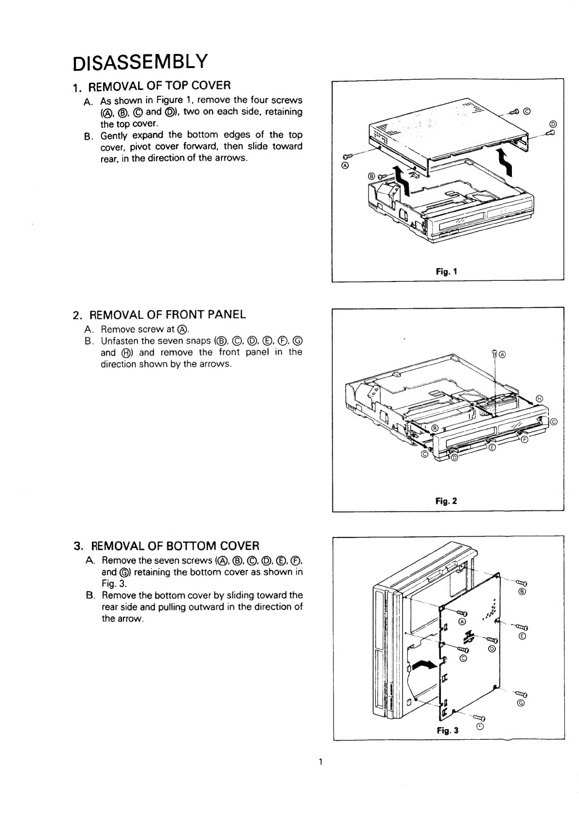
Disassembly
...............0::::ccccecsceereettteetnneeees
1
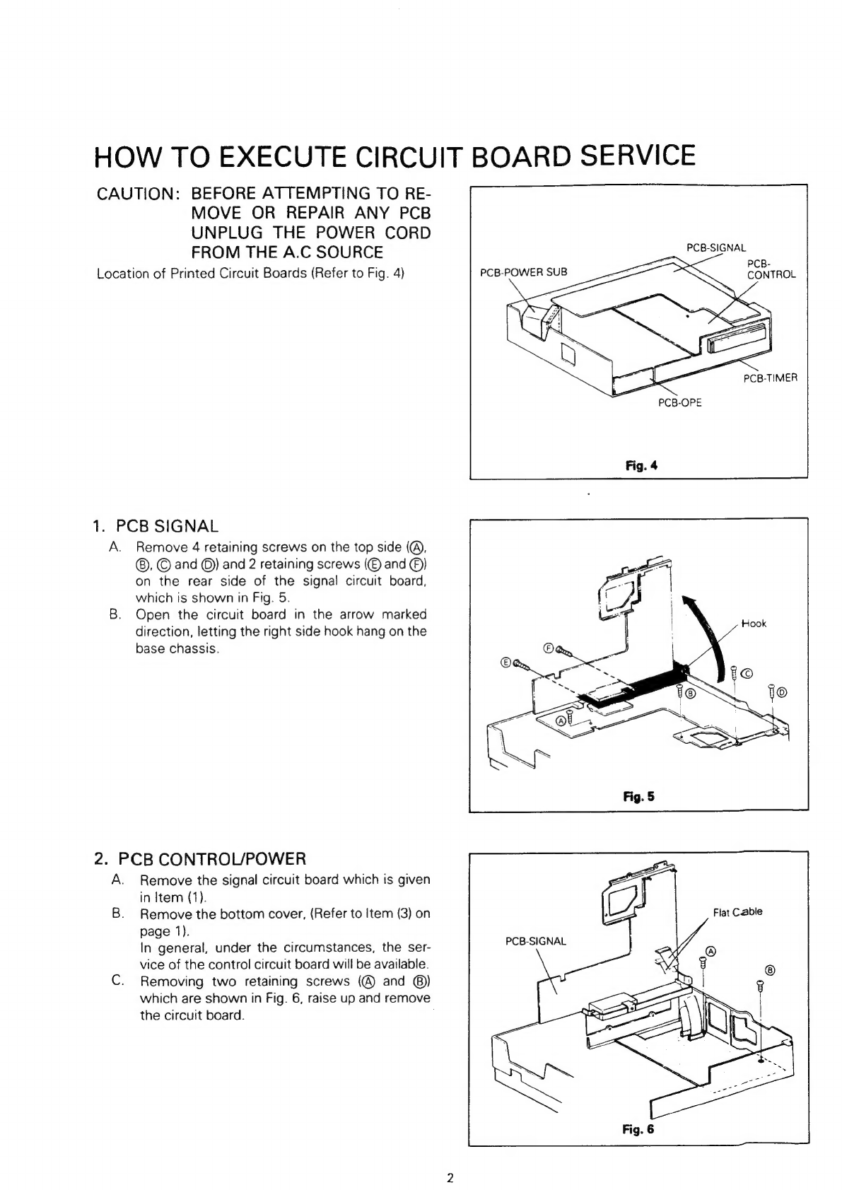
How
to
execute
Circuit
Board
service
..........
2
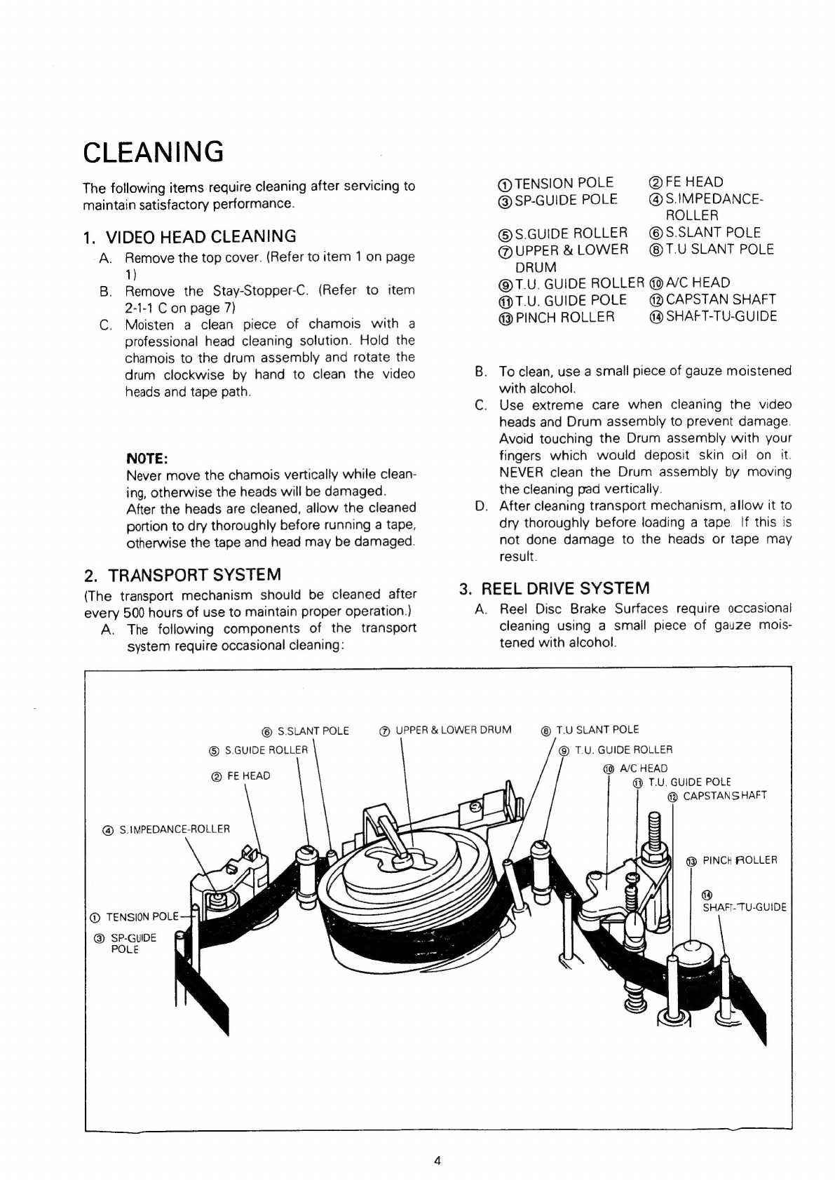
Cleaning
oo...
ec
eecee
eter
ere
tee
eee
eteertettaes
4
Mechanical
&
Electrical
Adjustment
TOOISS
oo
efxkcehiie
ee
eee
5
Major
component
removal
and
installation
...................00-:c
eee
f)
4-1
Picture
Control
Adjustment
...................55
7
1-2
Still
Adjustment
20...
ee
7
2.
Removal/Replacement
of
Primary
Parts
..0.0...0..0000
cee
eee
7
2-1
Replacement
of
Cassette
Housing
............
7
2-2
Replacement
of
Drum
Motor/Video
Head
ASSEMDIY
........eccceceeeceeeteteteettees
8
2-3
Replacement
of
Upper
Drum
.............
Ss)
2-4
Replacement
of
Capstan
Motor
..............5
9
2-5
Replacement
of
Belt
Ro...
ee
10
2-6
Replacement
of
Loading
Motor
..............-5
10
2-7
Replacement
of
Pinch
Roller
..............
10
.
Electrical
Adjustments
.................
ee
11
3-1
Servo
Circuit
Adjustments
............
ee
12
3-2
Y/C
Signal
Circuit
Adjustments
..............-
12
3-3.
Audio
Circuit
Adjustments
...............
ee
14
ne
4.
Mechanical
Adjustments
................0.....:.:05
15
4-1
Tension
Pole
Position
Adjustments
............
15
4-2
Installation
of
Master
Plane
Jig
.............0.
15
4-3.
Supply
Impedance
Roller
and
Take-up
Guide
Pole
Height
Check
and
ACJUSTMENE
...c
sed
seetinnnea
taney
aes
15
4-4
Reel
Disc
Height
Check
and
AGJUStMONT
cas
cise
anaes
sas
16
4-5
Arm
Take-up
Guide
Pole
Height
AdjUStMENE
oo...
eee
ee
eee
rete
eres
16
4-6
Back
Tension
Check
and
ACjUStMENt
oo...
eee
cette
teeter
16
4-7
Positioning
of
Gears
and
their
Installation
SEQUENCE
.......
ee
cee
17
4-8
Mode
Switch
Attachment
and
AdjUStMENE
oo...
eee
cece
eect
eeteeteeneees
17
4-9
Half
Loading
Unit
Adjustment
..............05
18
4-10
Tape
Path
Check
and
Adjustmen:
.
............
me)
4-11
Interchangeability
Adjustments
...
0.0.0...
.,
KEY
TO
ABBREVIATIONS
.................
-.005
25
Parts:
List
.
3c
canes
seoniec
eels
26
1.
CABINET
ASSEMBLY
..........c
ce
crete
26
2.
DECK
ASSEMBLY
0.0...
cceeecceeee
eee
etteeenees
27
3.
ELECTRICAL
PARTS
.0.....
ccc
eccceccuce
ceteris
31
4.
PACKING
PARTS.
.......ccccccceeeeeeeeenee
tetreeetenes
34
Circuit
Diagrams
cee