sEcTtoN
3
ADJUSTMENTS
Nqtes UUhen Maklng Adjustments
l. Adjusunents should beperformed in the order listed-
2. Use the following testtapes:
TY-71
II (8-909-81
2-00).....................................
Lævel
TY
-7
252
(E-909-822-00)
... Tracking
TY-7551 (8-909-81400) .............Funcrions
TY-308 (E-892-35E-00)
......................................
Blank
Usethe following torque meten
TW-7131
(E-909-708-71) ............FwD
3. Swirches
andcontrolsshould
besetasfollows unlessotherwise
specified.
5. Cleaning
of theRevolving Drum
(1) Foldachamois
(2-034-697-00)
or aknir clothinto4 or more
files,
slightlyimpregnate
it wirhacleaning
liquid (9-919-573-
00),andsoftly touch thedrum with it andmanually roratethe
drum slowly counærclockwise by 2 to 3 turns for cleaning.
(2) At thatdme, becarefrrl not to movethechamoisvertically ro
the
headtip.
Otherwise,
theheadtipmayprobably
bedamaged.
6. Becarefulnot tomoveRV I andRV2 onrhe
RFAMP boardin the
mechanism
assembly.
7. To adjustthe tapepath andguides,remove the holder
as
shown
inthediagram
andusetheDATholderjig
A). Thiswill makeit easier
to performadjusrments.
. Firstturning
the
pulley
counterclockwise
toput
itin
out stâtuswill. make removal and reattachment
of
holder
assemblyeasier.
. To performadjustmenE, turn the pulley clockwiseto put
in loading in status, load the cassette
tape and set the
switchto the ON position.
TIMERswitch
REC
MODEswitch
IMUT switch
REC
LEVELconnol
PHONES
LEVEL conrol
OFF
LONG
COAXIAL
Min.
Min.
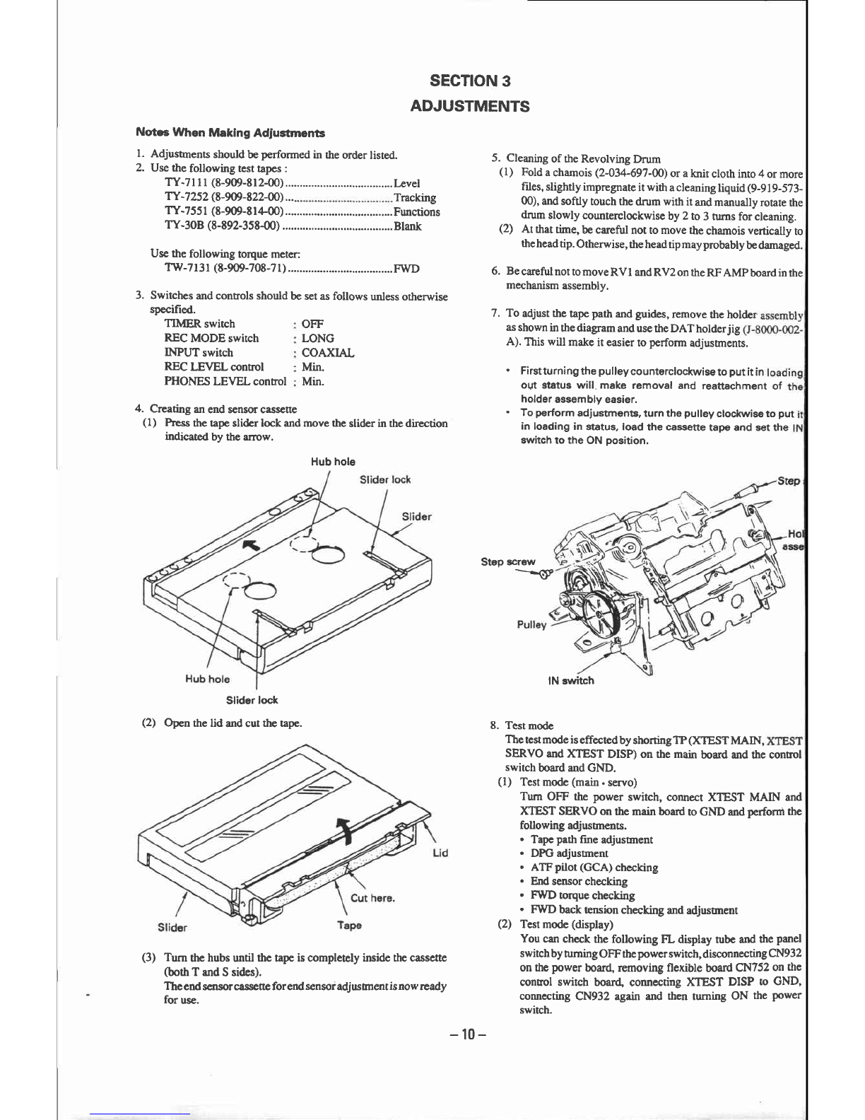
4. Creating anend sensorcassene
(l) Press
ûretapeslider lock andmove the slider in thedirection
indicated by the arrow.
Slider lock
(2) Opcn the lid andcut the tape.
Turnthe
hubs
untilthetapeiscompleælyinsidethecassette
(bothTandSsides).
The
ed sensorcassetteforend
sensoradjusrnentisnow
ready
for use.
IN3lrvitch
8. Testmode
Thetesmode iseffecædby shoningTP CXTESTMAIN,
SERVO
andXTESTDISP)onthemain
boardandthecontrot
switch
boardandGND.
(l) Testmode
(main.
sewo)
Tum OFF thepowerswitch,connecrXTEST MAIN and
XTEST
SERVOonthemainboard
toGNDand
perfonn
the
following
adjusunents.
. Tape
path
ftneadjustment
. DPGadjussnent
. ATFpilot(GCA)
checking
. Endsensorchecking
. F'WDrorquechecking
. FWD
backænsion
checking
andadjusrment
(2) Test
mode
(display)
Youcan
checkthefollowingFL displaytubeand
ttre
panel
switch
bytuming
OFFthe
power
switch,
disconnecting
CN932
onthe
power
board,removingfleûble board
CN752
onthe
controlswitch boand,
connecting
XTEST DISP to GND,
connccting
CN932againandthenturningON thepower
switch.
Step screw
---(P
Hubhole
(3)
-10-