Page 1 - 1
CHAPTER 1: INTRODUCTION TO THE 400ES SERIES DIGITAL INDICATORS
The 400ES Series Digital Indicator is a general purpose, industrial grade weight indicator
featuring keyboard tare and stainless steel enclosure. It can readout up to 50,000 display
divisions on its 0.56” tall LED display and can supply enough current for up to 4-350load cells.
All setup parameters may be entered via the front panel keys, including calibration.
If your Model 400ES Series Digital Indicator is part of a complete floor scale or has been installed
for you, you may skip to Chapter 7 for operating instructions. Prior to using the indicator, please
read this chapter carefully and completely. Store the manual in a safe and convenient place so it
will be available if you have questions concerning the operation of the scale.
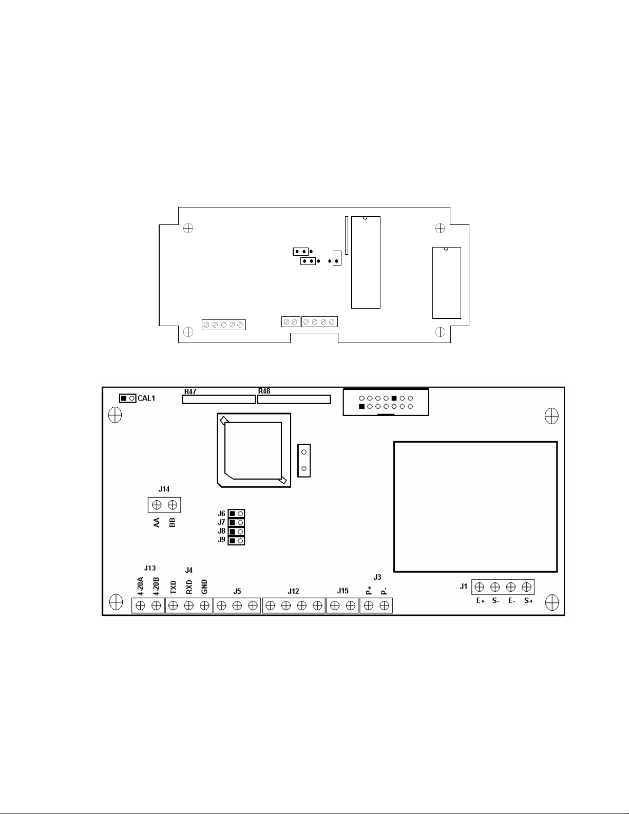
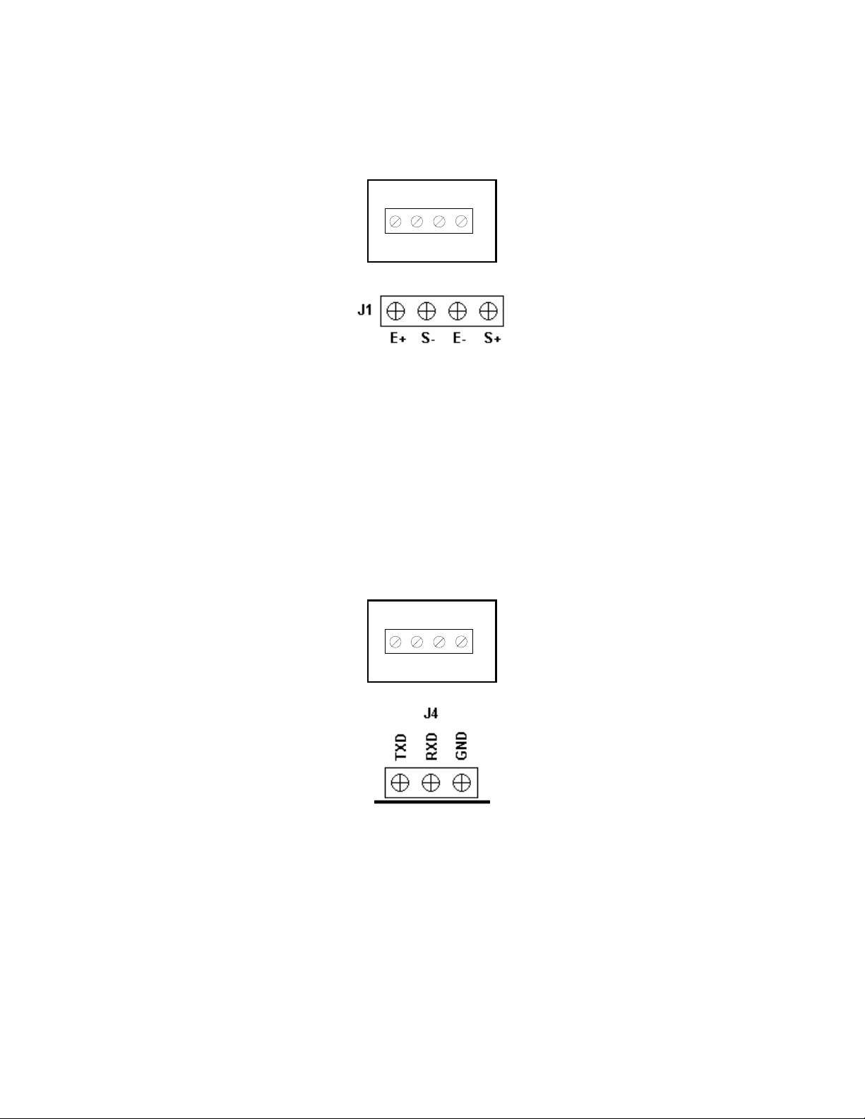
If you are an installer, the indicator's installation and wiring instructions are found in Chapter 2.
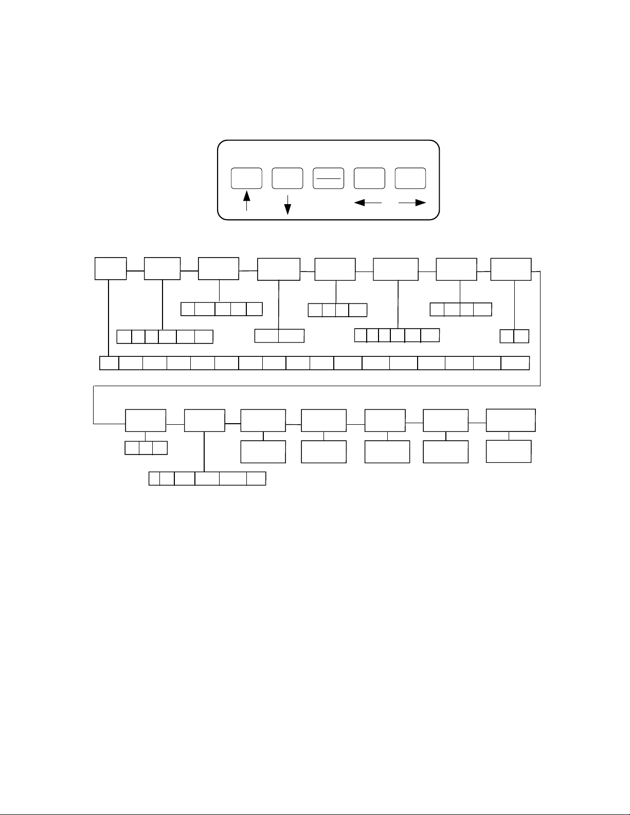
The indicator contains two main setup menus: The Setup (“F”) menu, which configures the
indicator to your weigh platform and the User (“A”) menu, which configures the serial
communication port and enables some user options. Chapter 3 gives an overview and explains
how to use the five front panel keys to maneuver and save settings in both menus. Chapters 4
and 5 explain the Setup and User Menu options, respectively. Chapter 6 covers system
calibration. Prior to installing the indicator, please read this manual carefully and completely.
Store the manual in a safe and convenient place so it will be available if you have questions
concerning the setup and operation of the scale.
DISP T
CLASS III = 5,000nmax
ZERO
NET
GROSS
TARE
lb
kg
MOTION
2 3 4 5
7 8 9 0
ZERO NE T 1
UNITS TARE 6
GROSS
CAPACITY 400ES
T
SAVE
DISP T PRINT
FIGURE 1-1: 400ES Front Panel
Your Model 400ES Digital Indicator contains a feature that allows you to print the current date on
the print ticket. This date is not stored or updated by the instrument and must be re-entered each
day.
To enter the date to be printed using the Date Entry procedure:
1. Ensure that A6 is set to Gross/Net/Tare print mode. See Chapter 3 for more information.
2. Remove power from the indicator, then re-apply power without holding down any keys.
3. The indicator will count down from all 6’s to all 1’s then will start to display dashes across the
screen one at a time from right to left.
4. BEFORE ALL SIX DASHES ARE DISPLAYED, use the front panel numeric keys to key-in the
desired date as you want it to appear in the printout. If you do not enter the first digit of the
date in time, simply start over from Step # 2. If you make a mistake entering the date, you may
use the ZERO key as a backspace key.
5. After entering the desired date, press the NET/GROSS key to save the value. The indicator
does not check for a valid date and resumes Normal Operating Mode.