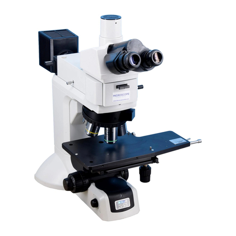
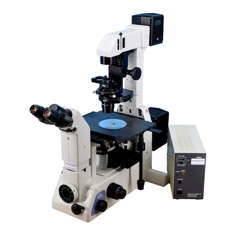
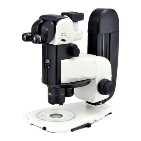
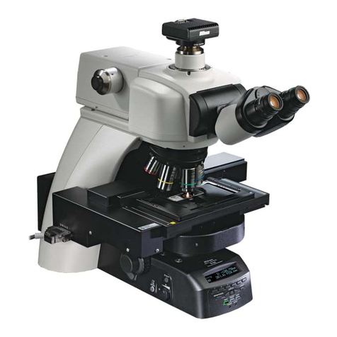
Nikon Eclipse E600 User manual

Nikon
Microscope
ECLIPSE
E600
Instructions

Thank
you
for
purchasing
the
Nikon
products.
This
instruction
manual
is
written
for
the
users
of
the
Nikon
Microscope
ECLIPSE
E600.
To
ensure
correct
usage,
read
this
manual
carefully
before
operating
the
instrument.
*
It
is
prohibited
to
reproduce
or
transmit
this
manual
in
part
or
whole
without
Nikon's
ex-
pressed
permission.
*
The
contents
of
this
manual
are
subject
to
change
without
notice.
+
Although
every
effort
has
been
made
to
ensure
the
accuracy
of
this
manual,
if
you
note
any
points
that
are
unclear
or
incorrect,
contact
your
nearest
Nikon
representative.
Warning/Caution
Symbols
Used
in
This
Manual
Although
Nikon
products
are
designed
to
provide
you
with
the
utmost
safety
during
use,
incorrect
usage
or
disregard
of
the
instructions
can
cause
personal
injury
or
property
damage.
For
your
safety,
read
the
instruction
manual
carefully
and
thoroughly
before
using
the
instru-
ment.
Do
not
discard
this
manual
but
keep
it
near
the
product
for
easy
reference.
In
this
manual,
safety
instructions
are
indicated
with
the
symbols
shown
below.
Be
sure
to
follow
the
instructions
indicated
with
these
symbols
to
ensure
correct
and
safe
operation.
Symbol
Meaning
AN
ARNING
Disregarding
instructions
marked
with
this
symbol
may
lead
to
death
or
serious
injury.
CAUTION
Disregarding
instructions
marked
with
this
symbol
may
lead
to
injury
/
\
or
property
damage.

Anne
1.
Intended
product
use
This
microscope
should
only
be
used
for
microscopic
observation.
Do
not
use
it
for
any
other
purpose.
Do
not
disassemble
Disassembling
may
cause
malfunction
and/or
electrical
shock.
Do
not
disassemble
any
paris
other
than
those
mentioned
in
this
manual.
If
you
notice
any
malfunction,
notify
your
nearest
Nikon
representative.
Input
voltage
Make
sure
that
the
input
voltage
indicated
on
the
back
panel
of
the
microscope
is
the
same
as
your
regional
voltage.
If
not
the
same,
do
not
use
the
microscope;
instead,
notify
your
nearest
Nikon
representative
immediately.
If
the
microscope
is
used
with
the
wrong
input
voltage,
a
short
circuit
or
fire
may
result,
causing
the
damage
of
the
microscope.
Power
cord
To
prevent
electrical
shock,
always
turn
off
the
power
switch
(flip
it
to
the
“
*"
side)
before
connecting
or
disconnecting
the
power
cord.
Use
only
the
following
power
supply
cord
set.
Using
the
wrong
power
cord
could
result
in
damage
or
fire.
*
For
100-120V
area
UL
Listed,
detachable
cord
set,
3
conductor
grounding
type
SVT,
No.
18
AWG
rated
at
125V,7A
minimum.
In
case
of
using
the
extension
cord,
use
only
the
power
supply
cord
with
the
PE
(protective
earth)
wire.
+
For
220-
240V
area
3
pole
power
supply
cord
set,
which
must
be
approved
according
to
EU/EN
standards.
Class
I
equipment
should
be
connected
to
PE
(protective
earth)
terminal.
In
case
of
using
the
extension
cord,
use
only
the
power
supply
cord
with
the
PE
(protective
earth)
wire.
Heat
from
the
light
source
The
lamp
and
the
lamphouse
become
extremely
hot.
To
avoid
burns,
do
not
touch
the
lamphouse
while
the
lamp
is
lit
or
for
thirty
minutes
after
it
has
been
turned
off.
Furthermore,
in
order
to
avoid
the
risk
of
fire,
do
not
place
fabric,
paper
or
highly
flammable
materials
such
as
gasoline,
petroleum
benzine,
paint
thinner
or
alcohol
near
the
lamphouse
while
it
is
lit
or
for
about
thirty
minutes
after
it
has
been
turned
off.
The
back
of
the
microscope
also
becomes
hot
during
use.
Although
this
is
not
a
malfunction,
be
careful
not
to
touch
the
back
of
the
microscope
when
it
is
hot.
Nikon
MODEL
ECLIPSE
E600
120V~
24A
50/60HZ
MADE
IN
JAPAN

[Nana
1.
Only
use
the
specified
halogen
lamp
The
power
supply
unit
in
the
microscope
provides
the
power
for
the
halogen
lamp
that
serves
as
the
microscope
light
source.
This
unit
can
supply
power
for
a
halogen
lamp
of
up
to
12
V-100
W.
The
specified
lamp
and
lamphouse
must
be
used,
otherwise,
the
microscope
could
be
damaged.
Specified
lamphouse:
Nikon
C-LP
HALOGEN
12V100W
model
Specified
lamp:
12V-100W
LONGLIFE
halogen
lamp
(OSRAM
HLX64623
or
PHILIPS
7724)
Precautions
for
replacing
the
lamp
To
prevent
burns,
allow
the
lamp
to
cool
for
at
least
thirty
minutes
after
turning
off
the
power
switch
before
replacing
it.
Furthermore,
to
prevent
electrical
shock
and
damage
to
the
microscope,
always
turn
off the
power
switch
(flip
it
to
the
“
>
side)
and
unplug
the
power
cord
before
connecting
or
disconnecting
the
lamphouse.
After
replacing
the
lamp,
be
sure
to
attach
the
lamphouse
cover
securely.
Never
use
the
lamphouse
without
its
cover.
Precautions
for
operating
the
stage
The
stage
rack
protrudes
when
the
stage
is
moved.
When
operating
the
focus
knobs
or
condenser
focus
knob,
be
careful
not
to
graze
your
hand
on
the
end
of the
rack.
Do
not
wet
the
microscope
If
the
microscope
gets
wet,
a
short
circuit
may
result
that
could
damage
it
or
make
it
extremely
hot.
If
you
accidentally
spill
a
liquid
on
the
microscope,
immediately
turn
off
the
power
switch
(flip
it
to
the
“
+”
side)
and
unplug
the
power
cord.
Then
use
a
dry
cloth
to
wipe
away
the
moisture.
If
any
liquid
gets
inside
the
microscope,
do
not
use
it;
instead,
notify
your
nearest
Nikon
representative.
Weak
electromagnetic
waves
This
microscope
emits
weak
electromagnetic
waves.
The
accuracy
of
any
precision
electronic
equipment
may
be
adversely
affected
if
positioned
too
close.
If
the
microscope
affects
TV
or
radio
reception,
move
the
radio
or
TV
further
away
from
the
microscope.
Precautions
for
installation
Be
careful
not
to
pinch
your
hands
or
fingers
when
installing
the
microscope.
This
microscope
is
a
precision
optical
instrument,
and
using
or
storing
it
under
unsuitable
conditions
may
damage
it
or
may
have
an
adverse
effect
on
its
accuracy.
See
“Installation
location”
on
p.
24
and
always
use
the
microscope
in
a
suitable
environment.

A
cures
7.
Precautions
for
moving
the
microscope
First
detach
the
lamphouse,
and
then
securely
hold
the
microscope
by
the
base
of
the
arm
from
the
back.
This
microscope
is
a
precision
optical
instrument,
so
handle
it
carefully
and
do
not
subject
it
to
a
strong
physical
shock.
(The
accuracy
of
the
objective
in
particular
may
be
adversely
affected
by
even
a
weak
physical
shock.)
In
addition,
do
not
grasp
the
focus
knobs,
eyepiece
tube,
stage,
etc.
when
carrying
the
microscope.
This
could
cause
the
part
to
come
off,
resulting
in
damage
to
the
microscope.

CONTENTS
Warning/Caution
Symbols
Used
in
This
Manual
ezine
see
ieenionionia
1
PAN
SA
2
LS
CAUTION
ccoo
errores
3
il
Names
of
Component
Parts
and
Operational
PartS...........................-srerrercenerienicane:
6
H
Microscobp
ツ
tirrenia
rioni
rien
rioniie nie
iene
페미
8
El
OperationofEachPart..............................................
0.0000
aneen
aaa
enne
oro
rro
riores
13
Coarse
and
fine
focus
knobs
ii
13
1.
Rotation
of
the
coarse
and
fine
focus
knobs
and
vertical
movement
of
the
stage
..................
i
13
2.
Adjusting
the
torque
of
the
coarse
focus
knob
nn...
13
3.
Coarse
focus
stoDDeT
e
eee
14
Eyepiece
tube
optical
path
selection
(T
eyepiece
tube,
F
eyepiece
tube)
...............
15
1.
Vertical
tube
adapter
i
15
2.
TandF
eyepiece
tubes
lever
clickind
上
…
せ
ドー
トー
タート
ーー
15
Diopter
adjustment
en
16
EJ
Interpupillary
distance
adjustment
nn
16
Condenser
μμ
----,,,,
17
1.
Focusing
and
Centering
ss
e
Pen
17
2.
Condenser
aperture
diaphragm
eee
nene
een
ena
0
18
3.
Objectiveandceondensercombinations....................................
19
E
Field
diaphragm
nın
19
Filters...
ИИНИ
20
EJ]
Stage
ОА
20
1.
Adjusting
the
torgue
ofthestagemotioncontrolknobs.....................................
20
2.
Stage
rotation...............
issues
K
K
RKK
21
E]
Auto-photo
switch
(for
photomicrography)
ーーoooeeeeeeeeeww
21
Oil-immersion
operation
.............
sise
22
Water-immersion
operation
sers
23
ASSEMDIY
............e
renne
nie
rerian
reni
can
aenienera
nec
eee
nie
nieonanienisanienice
seneca
niaenicniene
zen eve
nienienina
24
1.
Confirming
the
input
voltage
eee
eee
nn
nee
nen
n
tn
25
2.
Lamp
and
lamphouse
installation
and
removal
(lamp
replacement)
...................
26
NS
EA
27
4.
Revolving
nosepiece
assembly
nr
nn
na
nan
once
28
5.
Eyepiece
tube
assembly
ii
28
6.
Connecting
the
power
cord...
si
1.11
29
7.
Installing
separately
sold
accessories
i
29
Troubleshooting
Tables
.…........................................
nn
n
Kne
30
Viewing
and
control
Systems
.ps
30
Electrical
system
see
33
[3
Care
and
Maintenance
μμ
μμ”
---ϱ------ϱϱ-ϱ--ρ---
34
Electrical
Specifications
osse
serene
seeren
renee
En
Eee
renerne
35
ASS
36

Names
of
Component
Parts
and
Operational
Parts
If
the
microscope
has
not
yet
been
assembled,
see
chapter
“4.
Assembly”
first.
Photomicrographic
vertical
tube
adapter
Trinocular
eyepiece
tube
Diopter
adjustment
ring
Eyepiece
Specimen
holder
(AS.
|
Condenser
clamp
ロン
タジク
Q
(O
screw
SS
AS
——
>
>
Condenser
focus
knob
+
Revolving
nosepiece
Coarse
torque
adjustment
ring
(TORQUE)
Objective
Coarse
focus
knob
Fine focus
knob
N
J
X
DN
N
|
Stage
Brightness
adjuster
DN
Stage
rotation
(LAMP)
clamp
screw
|
Auto-photo
switch
AT
|
Auto-photo
voltage
selection
switch

1.
Names
of
Component
Parts
and
Operational
Parts
Condenser
aperture
scale
Condenser
aperture
diaphragm
ring
Condenser
Photomicrographic
equipment
clamp
screw
selection
lever
cm
Eyepiece
tube
clamp
screw
Revolving
nosepiece
clamp
screw
Substage
clamp
screw
Filter
release
lever
7
>
Filter
insertion
lever
Y-axis
stage
motion
control
knob
Fine
focus
knob
Field
diaphragm
ring
TŽ
TT
a
Power
switch
Field
lens
X-axis
stage
motion
a
control
knob
Coarse
focus
stopper
ring
(CLAMP)
=
|
AA
ON
X
Curse
Nikon
6600
Diffuser
insertion/
removal
screw
Tool
holder
Rating
label
Lamphouse
AC
input
connector
Power
cord

Microscopy
The
general
procedure
for
microscopy
is
described
below.
For
details
on
each
step,
refer
to
the
corresponding
item
in
chapter
“3.
Operation
of
Each
Part.”
If
the
microscope
has
not yet
been
assembled,
see
chapter
“4.
Assembly”
first.
Turn
on
the
power.
(Flip
the
switch
to
the
«
|
”
side.)
As
soon
as
the
power
comes
on,
the
switch
lights.
Flip
the
switch
to
the
“
|
"side.
Set
the
brightness
adjuster
to
give
the
desired
brightness.
Pressing
the
auto-photo
switch
will
set
the
voltage
for
the
brightness
that
provides
the
best
color
reproduction.
(p.
21)
Adjust
the
Insert
filters
ND
16
or
4
Insert
filters.
—
brightness.
and
NCBII
into
the
Auto-photo
switch
optical
path.
can
be
pressed.
ND
16
or
4
reduces
glare
in
the
binocular
eyepiece.
NCB11
improves
color
reproduction.
(p.
20)
Move
the
10x
objective
into
the
optical
path.
Rotate
the
revolving
nosepiece
until
the
10x
objective
clicks
into
place.
El
Set
the
10x
objective.
Set
the
specimen
in
place
with
the
cover
glass
facing
up.

2.
Microscopic
Procedure
Raise
the
condenser
as
high
as
it
will
go.
Fully
open
the
field
diaphragm
and
condenser
|
aperture
diaphragm.
Move
the
specimen
until
the
portion
to
be
viewed
is
in
the
optical
path.
(p.
20)
Loosen
the
coarse
focus
stopper
ring.
Rotate
it
in
the
direction
opposite
the
arrow
on
the
base
as
far
as
it
will
go.
(p.
14)
I
Raise
the
—
condenser.
Fully
open
the
condenser
Fully
open
the
aperture
diaphragm.
field
diaphragm.
El
Set
the
portion
El
Loosen
the
coarse
to
be
viewed
in
focus
stopper.
the
optical
path.
+

Set
the
optical
path
to
100%
of
the
binocular
||
eyepiece
when
using
a
|
triocular
eyepiece
tube.
2
(p.15)
Focus
on
the
specimen.
(p.
13)
Adjust
the
diopter
rings
of
both
eyepieces.
(p.
16)
Adjust
the
interpupillary
distance.
(p.
16)
Focus
on
the
specimen.
o
ins
li
Set
the
optical
path
to
100%
of
the
binocular
eyepiece.
Adjust
the
diopter
rings.
Adjust
the
interpupillary
distance.
10

2.
Microscopic
Procedure
Focus
and
center
the
condenser.
(p.
17)
Switch
to
any
desired
objective
and
view
the
|
specimen.
Rotate
the
revolving
nosepiece
to
its
click-stop
©
position.
Readjust
the
focus.
Use
ND
filters
to
adjust
the
brightness.
[i
Focus
the
LU
|
condenser.
Center
the
e600
condenser.
{7A
Adjust
the
brightness
with
回
Swi
回
Switch
the
ND
filters.
objective.
A
IB
Readjust
the
=
focus.
11

2.
Microscopic
Procedure
Close
the
field
diaphragm
so
that
it
is
just
outside
the
lose
th
denser
field
of
view.
(p.
19)
EC
e
conden
aperture
diaphragm.
Close
the
condenser
aperture
diaphragm
to
¿about
70
—
80%
of
the
numerical
aperture
of
the
objective.
(p.
18)
I]
Close
the
field
diaphragm.
Cura
portion
of
the
field
of
view
is
dark,
adjust
the
condenser
centering
screws.
If
that
does
not
resolve
the
problem,
check
the
following
items:
*
Filter
insertion/removal
(p.
20)
¢
Optical
path
selection
for
the
eyepiece
tube
(p.
15)
*
Position
of
the
revolving
nosepiece
(p.
11)
*
Revolving
nosepiece
installation
(p.
28)
+
Lamp
installation
(p.
26)
*
Condenser
focusing
and
centering
(p.
17)
+
Field
and
aperture
diaphragms
(p.
18
and
19)
¢
Condenser
installation
(p.
27)
M
If
it
is
not
possible
to
focus
on
the
specimen,
check
the
following
items:
*
Mounting
of
the
specimen
(p.
31
and
32)
*
Release
of
the
coarse
focus
stopper
(p.
14)
¢
Thickness
of
the
cover
glass
(0.17
mm
is
standard)
(p.
31
and
32)
12

Operation
of
Each
Part
1
Coarse
and
fine
focus
knobs
|
1.
Rotation
of
the
coarse
and
fine
focus
knobs
and
vertical
movement
of
the
stage
NS
Rotating
the
fine
focus
knob
one
step
moves
the
stage
1
um.
Rotating
the
fine
focus
knob
one
complete
turn
moves
the
stage
0.1
mm.
Rotating
the
coarse
focus
knob
one
complete
turn
moves
the
stage
12
mm.
The
coarse/fine
focus
stroke
(range
of
vertical
motion)
for
the
stage
is
2
mm
up
and
23
mm
down
from
the
reference
(focused)
position.
Never
attempt
either
of
the
following
actions
These
actions
will
damage
the
microscope.
¢
Rotating
the
left
and
right
knobs
in
opposite
directions
at
the
same
time.
«
Continuing
to
rotate
the
coarse
focus
knob
after
the
stage
has
reached
the
limit
of
its
mo-
tion.
|
2.
Adjusting
the
torque
of
the
coarse
focus
knob
BE
It is
possible
to
adjust
the
torque
of
the
coarse
focus
knob.
\ \ \ \
\
To
increase
the
torque,
turn
the
torque
adjustment
ring
(TORQUE)
located
behind
the
coarse
focus
knob
in
the
\
\ \
\
\
direction
of
the
arrow
on
the
microscope
base
(i.e.,
the
\ \ \ \
counter-clockwise
direction).
To
reduce
the
torque,
turn
\
い
VA
the
ring
in
the
direction
opposite
to
the
arrow
(i.e.,
the
\
clockwise
direction).
To
increase
the
torque
13

3.
Coarse
focus
stopper
NS
Clamp
the
coarse
focus
stopper
Purpose
of
the
coarse
focus
stopper
The
coarse
focus
stopper
marks
the
stage
position
at
which
the
specimen
is
in
focus
by
restrict-
ing
the
movement
of
the
coarse
focus
knob.
(Movement
of
the
stage
by
the
fine
focus
knob
is
not
restricted.)
Once
the
coarse
focus
stopper
has
been
clamped
in
position,
the
coarse
focus
knob
cannot
be
used
to
move
the
stage
any higher.
In
effect,
once
the
coarse
focus
knob
has
been
clamped
in
place
at
the
focus
position,
a
rough
focus
can
be
attained
the
next
time
simply
by
turning
the
coarse
focus
knob
as
far
as
it
will
go.
This
feature
is
convenient
when
viewing
similar
speci-
mens
one
after
another.
Using
the
coarse
focus
stopper
With
the
specimen
in
focus,
turn
the
coarse
focus
stopper
ring
as
far
as
it
will
go
in
the
direction
of
the
arrow
on
the
base
of
the
microscope
(about
3/4
revolution).
The
coarse
focus
stopper
is
now
clamped
in
position.
When
changing
the
specimen,
lower
the
stage
by
turning
only
the
coarse
focus knob.
After
changing
the
specimen,
gently
raise
the
stage
by
turning
only
the
coarse
focus
knob
as
far
as
it
will
go.
The
specimen
should
be
roughly
in
focus
when
the
stage
has
been
raised
as
far
as
it
will
go;
use
the
fine
focus
knob
to
bring
the
specimen
into
perfect
focus.
If
the
coarse
focus
stopper
is
not
being
used,
be
sure
to
turn
the
coarse
focus
stopper
ring
in
the
direction
opposite
to
the
arrow
on
the
microscope
base
as
far
as
it
will
go.
14

3.
Operation
of
Each
Part
2
Eyepiece
tube
optical
path
selection
=
(T
eyepiece
tube,
F
eyepiece
tube)
The
optical
path
selection
lever
can
be
used
to
select
the
way
to
divide
the
amount
of
light
between
the
binocular
part
and
the
vertical
tube.
Light
proportion
Light
proportion
Lever
binocular
vertical
Lever
binocular
vertical
position
part
tube
position
part
tube
Ш
100
:
ο
FAT]
sino—-
1]
100
:
0
/
„a
0
:
100
BINO&
F-
PHOTOT
[2] 20
:
80
o
em
00
FEI
PHOTO-
0
:
100
BINO
PHOTO
Tİ
13]
+
PS
T
eyepiece
tube
F
eyepiece
tube
Vi.
vertical
tube
adapter
A
photomicrographic
vertical
tube
adapter
is
pro-
vided
as
standard
equipment
that
allows
a
photomi-
crographic
equipment
to
be
installed.
To
install
the
adapter,
insert
it
into
the
vertical
tube
and
clamp
three
screws
with
the
provided
screwdriver.
Re-
place
this
adapter
with
the
optional
TV
vertical
tube
adapter
when
using
a
TV
camera.
2.
T
and
F
eyepiece
tubes
lever
clicking
There
is
a
switch
identified
by
“NO
CLICK”
on
the
bottom
surface
of
the
eyepiece
tube.
Turn
the
switch
in
the
direction
of
the
arrow
with
the
hexagonal
screwdriver
provided
to
disengage
the
clicking
ac-
tion
of
the
optical
path
selection
lever.
Disengag-
ing the
clicking
action
minimizes
small
vibrations
produced
by
operating
the
lever.
15

3
Diopter
adjustment
xd
Engraved
line
Diopter
adjustment
"0"
position
'
=
Diopter
adjustment
compensates
for
differences
in
eyesight
between
the
left
and
right
eyes.
In
addition
to
making
observation
through
both eyes
easier,
this
adjustment
also
reduces
the
difference
in
focus
when
changing
the
objectives.
Adjust
the
diopter
setting
for
both
eyepieces.
1
Turn
each
diopter
adjustment
ring
on
both
eyepieces
to
align
the
edge
of
the
ring
with
the
engraved
line.
This
is
the
“O”
position.
2
Perform
steps
MJ
to
IJ
in
chapter
“2.
Microscopic
Procedure”
so
that
the
specimen
is
in
focus
with
the
10x
objective.
3
Move
the
40x
objective
into
the
optical
path.
Turn
the
coarse
and
fine
focus
knobs
to
focus
on
the
specimen.
4
Move
the
4x
or
10x
objective
into
the
optical
path.
5
Turn
the
diopter
adjustment
ring
on
each eyepiece,
not
the
coarse
and
fine
focus
knobs,
to
bring
the
specimen
into
focus,
while
peering
through
the
right
eyepiece
with
your
right
eye
and
the
left
eyepiece
with
your
left
eye.
6
Repeat
steps
3 to 5
twice.
Interpupillary
distance
adjustment
Before
adjusting
the
interpupillary
distance,
performs
steps
MN
to
KE
in
chapter
“2.
Microscopic
Procedure”
so
that
the
specimen
is
in
focus
with
the
10x
objective.
Adjust
the
interpupillary
distance
so
that
the
view
field
for
each
eye
is
at
the
same
position
on
the
specimen.
Doing
so
will
make
observation
through
the
binocular
eyepiece
with both eyes
easier.
16

3.
Operation
of
Each
Part
っ
Condenser
N
一
1.
Focusing
and
centering
e
Eyepiece
view
field
yepiece
view
field
Focus
and
center
the
condenser
so
that
the
light
passing
through
the
condenser
forms
the
image
at
the
correct
position
on
the
specimen
(i.e.,
at
the
center
of
the
optical
path).
Before
focusing
and
centering
the
condenser,
perform
steps I
to
KE]
in
chapter
“2.
Microscopic
Procedure”
so
that
the
specimen
is
in
focus
with
the
10x
objective.
Close
the
field
diaphragm
to
its
minimum
setting.
Turn
the
condenser
focus
knob
so
that the
image
of
the
field
diaphragm
is
formed
on
the
specimen.
Make
rough
adjustments
with
the
condenser
centering
screws
so
that
the
image
of
the
field
diaphragm
appears
at
the
center
of
the
eyepiece
view
field.
Move
the
40x
objective
into
the
optical
path.
Turn
the
fine
focus
knob
to
focus
on
the
specimen.
Turn
the
condenser
focus
knob
so
that the
image
of
the
field
diaphragm
is
formed
on
the
specimen.
Adjust
the
condenser
centering
screws
so
that
the
image
of
the
field
diaphragm
appears
at
the
center
of
the
eyepiece
view
field.
This
adjustment
is
easier
to
make
if
you
adjust
the
size
of
the
field
diaphragm
to
be
slightly
smaller
than
the
eyepiece
view
field.
17

§
2.
Condenser
aperture
diaphragm
Numerical
Plan
40X
_
Aperture
40x
/:0.75°
RE
©
-WD
22
0.75X0.7~0.8=0.525~0.6
The
aperture
diaphragm
is
important
because
it
is
related
to
the
resolution,
contrast,
depth
of
focus
and
brightness
of
the
optical
image.
Turning
the
condenser
aperture
diaphragm
ring
changes
the
size
of
the
aperture
diaphragm.
As
the
aperture
diaphragm
is
stopped
down,
resolution
and
brightness
are
reduced
while
contrast
and
depth
of
focus
are
increased.
Conversely,
as
the
aperture
diaphragm
is
opened,
resolution
and
brightness
are
increased
while
contrast and
depth
of
focus
are
reduced.
It is
not
possible
to
adjust
one
pair
of
characteristics
without
affecting
the
other.
Generally,
a
satisfactory
image
with
appro-
priate
contrast
can
be
obtained
with
an
aperture
setting
that
is
70%
to
80%
of
the
numerical
aperture
of
the
objective.
The
numerical
aperture
is
indicated
on
the
barrel
of
each objective.
An
indication
of
40x/0.75
means
that
the
magnification
is
40x
and
the
numerical
aperture
is
0.75.
If
the
aperture
diaphragm
is
stopped
down
too
far,
the
resolution
is
reduced;
therefore,
except
when
viewing
a
nearly
transparent
specimen,
we
do
not
recommend
stopping
down
the
aperture
to
less
than
60%
of
the
numerical
aperture
of
the
objective.
Adjusting
the
size
of
the
aperture
diaphragm
according
to
the
condenser
scale
Since
the
condenser
scale
indicates
the
numerical
aperture,
adjust
the
aperture
diaphragm
ring
according
to
the
scale.
(Normally,
the
index
on
the
aperture
diaphragm
ring
should
be
aligned
with
the
scale
line
corresponding
to
70%
to
80%
of
the
numerical
aperture
of
the
objective.)
Adjusting
the size
of
the
aperture
diaphragm
by
using
a
centering
telescope
(sold
separately)
Remove
one
of
the
eyepieces
and,
by
using
a
special
adapter
(sold
separately),
mount
a
centering
telescope
in
its
place.
Turn
the
aperture
diaphragm
ring
to
stop
down
the
aperture
diaphragm
as
far
as
possible.
While
holding
down
the
flange
of
the
telescope,
turn
the
eyepiece
of
the
center-
ing
telescope
and
focus
on
the
aperture
diaphragm.
Turn
the
aperture
diaphragm
ring
to
adjust
the
size
of
the
aperture
diaphragm.
(Normally,
the
aperture
diaphragm
should
be
adjusted
so
that
it
is
about
70%
to
80%
of
the
size
of
the
field
being
viewed.)
Remove
the
centering
telescope
and
adapter,
and
then
re-fit
the
eyepiece.
18

3.
Operation
of
Each
Part
3.
Objective
and
condenser
combinations
|
C
-
ondenser
та
Swing-out
Achromat
Abbe
00
.
Objective
aplana
condenser condenser
condenser
magnification
magnification
condenser
condenser
1x
x
x x x
2x
x
x
x
©
(Note
2)
©
(Note
3)
4x
x
O
(Note
1)
|
O
(Note
1)
10x
to
100x
©
O O
O
x
©
:Optimum
©:
Appropriate
—
X:
Inappropriate
Note
1:
The
entire
view
field
may
not be
satisfactory
when
a
UW
eyepiece
is
used.
Note
2:
Indoor
lighting
and
similar
light
sources
may
be
reflected
from
the
surface
of
the
condenser
lens
and
be
visible
within
the
view
field.
When
this
happens,
either
dim
the
indoor
lighting
or
prevent
strong
outside
light
from
entering
the
stage.
Note
3:
Swing
out
the
top
lens
before
usage.
¢
Depending
on
the
type
of
objective,
the
whole
numerical
aperture
of
the
objective
may
not
be
covered.
For
example,
when
an
objective
with
an
N.A.
of
1.4
is
used,
the
aperture
size
of
the
swing-out
condenser
or
the
abbe
condenser
will
only
be
about
65%
of
the
objective's
N.A.
even
when
it
is
fully
opened.
*
Refer
to
the
condenser
instruction
manual
for
details
of
universal
and
phase
contrast
condensers.
6
Field
diaphragm
The
field
diaphragm
restricts
illumination
to
the
area on
the
specimen
being
viewed.
Turning
the
field
diaphragm
ring
changes
the
size
of
the
field
diaphragm.
For
normal
observation,
the
size
of
the
diaphragm
should
be
slightly
larger
than
the
boundary
of
the
view
field.
If
a
broader
area
than
necessary
is
illuminated,
stray
light
will
enter
the
view
field,
creating
flaring
and
reducing
the
con-
trast
of
the
optical
image.
The
correct
setting
of
the
field
diaphragm
is
especially
important
in
photomicrography;
generally,
good
results
are
obtained
by
stopping
down
the
field
diaphragm
to
just
slightly
larger
than
the
area
that
will
be
reproduced
on
the
film,
i.e.,
the
size
of
the
photo
frame.
19
Other manuals for Eclipse E600
2
Table of contents
Other Nikon Microscope manuals

Nikon
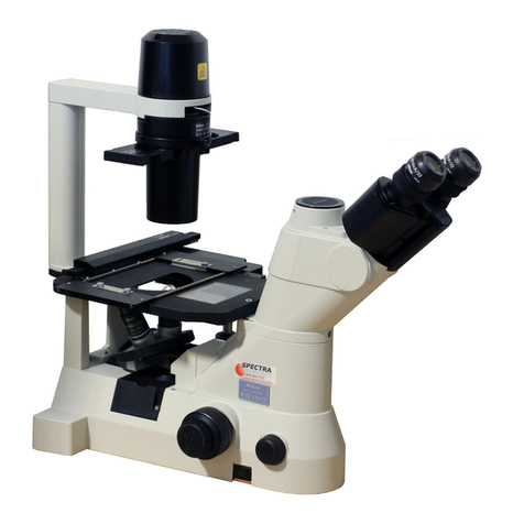
Nikon ECLIPSE Ni-E User manual

Nikon
Nikon SMZ-U User manual

Nikon
Nikon SMZ1000 User manual

Nikon
Nikon Eclipse TS100 User manual

Nikon
Nikon 50i User manual

Nikon
Nikon eclipse fn1 User manual

Nikon
Nikon Elcipse TE2000 User manual

Nikon
Nikon ECLIPSE Si User manual

Nikon
Nikon Eclipse E400 POL User manual

Nikon
Nikon Eclipse TE200 User manual

Nikon
Nikon Eclipse Ti TIFT 1454 User manual

Nikon
Nikon Eclipse Ni-U User manual

Nikon
Nikon SMZ-U Manual

Nikon
Nikon eclipse e100 User manual

Nikon
Nikon ECLIPSE Ei User manual

Nikon
Nikon T1-FM User manual

Nikon
Nikon LABOPHOT2-POL User manual

Nikon
Nikon ECLIPSE 80i User manual

Nikon
Nikon Eclipse L150 User manual

Nikon
Nikon SMZ1500 User manual