Salus SR600 User manual

SR600 - FULL USER MANUAL

TABLE OF CONTENTS
1. Introduction...............................................................................................................................................................4
1.1 Product Compliance ......................................................................................................................................................................4
1.2 Safety Informations.......................................................................................................................................................................4
2. Product Overview .......................................................................................................................................................5
2.1 Package content............................................................................................................................................................................6
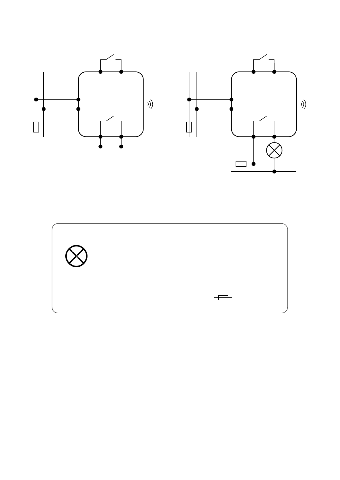
3. Connection description ...............................................................................................................................................7
4. About ZigBee network ................................................................................................................................................8
4.1 ZigBee network - creation and work..............................................................................................................................................8
5. Before you start (rst power up) ..................................................................................................................................9
5.1 Button operation...........................................................................................................................................................................9
5.2 LED Indication ...............................................................................................................................................................................9
6. Installation by SALUS Smart Home application (ONLINE MODE).....................................................................................10
6.1 General informations about SALUS Smart Home application.......................................................................................................10
6.2 Pairing with UGE600 universal gateway......................................................................................................................................11
7. OPERATING in ONLINE MODE (by app) ..........................................................................................................................13
7.1 General informations...................................................................................................................................................................13
7.2 App icons description ..................................................................................................................................................................13
7.3 Change device’s name (pencil icon).............................................................................................................................................14
7.4 Switching ON / OFF smart relay using Salus Smart Home app (manual mode)............................................................................15
7.5 Schedule mode............................................................................................................................................................................16
7.6 Temporary override mode ...........................................................................................................................................................19
7.7 Identication mode.....................................................................................................................................................................20
7.8 Pinning/unpinning SR600 to/from application dashboard..........................................................................................................21
7.9 Advanced settings.......................................................................................................................................................................22
7.10 OneTouch rules (add/edit) ........................................................................................................................................................24
7.11 Error codes (exclamation mark in app) ......................................................................................................................................33
7.12 Wireless signal strength test......................................................................................................................................................34
7.13 Factory reset (removing device from the app and ZigBee network)...........................................................................................35
8. Cleaning and Maintenance ........................................................................................................................................37
9. Technical Informations..............................................................................................................................................37
10. Warranty ................................................................................................................................................................38


4
This product complies with the essential requirements and other relevant provisions of Directives 2014/53/EU and 2011/65/EU. The full text of the EU
Declaration of Conformity is available at the following internet address: www.saluslegal.com.
• Before starting installation work and before using the product, read the entire manual.
• The information contained in the instructions is essential for proper functioning.
• To avoid accidents resulting in personal injury and material damage, please follow all safety precautions, specied in this manual.
• The device should not be used by people with limited mental, sensory or mental abilities, without experience, of insucient knowledge as well as
children.
• Do not use an unassembled device (eg without a cover).
• The device may only be opened by a qualied person.
• Keep electrical devices out of the reach of children and ensure that they do not play with it. Children should not be left unattended. If necessary,
disconnect the control system for the entire room.
• Do not leave the packaging, cabinet, or any loose parts of the device unattended, as they pose a risk to children.
WARNING!
• Installation must be carried out by a qualied person with appropriate electrical qualications in accordance with standards and regulations in force in
the given country and in the EU.
• Never try to connect the device other than as described in the manual.
• Before assembly, repair or maintenance as well as during any connection works it is absolutely necessary disconnect the mains supply and make sure
that the terminals and electric wires are not live.
• The device may not be exposed to extreme temperatures, strong vibrations or subjected to mechanical shock.
• The device should not be used in unfavorable environmental conditions or in rooms where there is a concentration of ammable gases, fumes or dust.
WARNING!
• There may be additional protection requirements for the entire installation that the installer is responsible for maintaining.
1. Introduction
1.1 Product Compliance
1.2 Safety Informations
Care for the natural environment is of paramount importance to us.The awareness that we manufacture electronic devices obliges us
to dispose of used electronic components and devices safely. Therefore the company has received a registration number issued by the
Chief Inspector for Environmental Protection.The crossed out symbol the trash can on the product means that the product must not be
disposed of with ordinary waste containers. Sorting waste for recycling helps to protect the environment. It is the user’s responsibility
to surrender used equipment to a designated collection point for recycling waste from electrical and electronic equipment.

5
Smart Relay SR600 is a remotely controlled device, designed to work in a switch box or wall socket, or wherever there is a need to control a receiver with
a maximum load of 16A. This product must be used with the UGE600 internet gateway (purchased separately) as the relay is programmed via the Salus
Smart Home internet application. The UGE600 internet gateway also enables communication with other iT600RF system products using the Salus Smart
Home Application.
In its simplest form, the SALUS Smart Home system cleverly allows you to control and manage your heating from anywhere using an app from your
Smartphone,Tablet or PC. Heating control is at the heart of an eective Smart Home system and in terms of eciency will have the largest positive eect
in reducing energy bills. A simple connected thermostat with smart heating controls can ensure your home is always at a comfortable temperature and
reduce waste by only heating specic rooms when and where you need them.
SALUS Smart Home oers three types of heating solutions. Choose between electric, hydronic and underoor systems. All can be scheduled and controlled
from anywhere via your Smartphone, Tablet or PC. You no longer need to heat an empty home and you can return to a warm one. Giving comfort and
saving money on expensive heating bills.
Starting with heating controls as a base, it is easy to unlock the true power of the SALUS Smart Home system just by adding a few very simple and easy to
install devices. Linked wirelessly to the SALUS Universal Connection Gateway and controlled remotely from the clear intuitive SALUS Smart Home app, the
system operation can then be tailored precisely to your needs.The clear but powerful software then allows you to create the exact functions you want to
add comfort, safety, security and convenience to your home.
Control:
• Online - using the SALUS Smart Home application and the UGE600 universal gateway
Product advantages:
• remote relay for voltage devices (boilers, pumps, valves, actuators, lighting and other 230V devices)
• remote relay for voltage free devices
• (alarm control panels, gate controllers, opening sensors and others)
• works as a repeater for ZigBee network
• can be used as a„smart input”to the system (you can activate OneTouch rules)
• has a programmable schedule in the application SALUS Smart Home
2. Product Overview

6
2.1 Package content
1) SR600
2) Short instruction
Please note:
Because of re and explosion risk there is not allowed to use device in atmosphere of explosive gases and ammable liquids (eg coal dust). In case if
any of listed dangers occur you have to use additional protection measures – anti-dust and explosive gases (tight cover) or prevent their formation.
Furthermore, device can’t be used in condensation of water vapor conditions and be exposed to water action.
1 2
SR600
Manual
V 2020 [ENG]

7
3. Connection description
N
L
COM
Wejściowe styki
sterujące
Beznapięciowe
styki wyjściowe
NO
S1 S2
SR600
L
AC 230V
N
N
L
COM
Wejściowe styki
sterujące
Max 16A
NO
S1 S2
SR600
L
AC 230V
N
L
AC 230V
N
L, N - power supply 230V
COM, NO - voltage-free output
S1, S2 - input terminals
- fuse
Legend: Symbols explanation:
Controlled device
Shutter
power
Volt-free input Volt-free input
Max load 16A
Volt-free output

8
4. About ZigBee network
4.1 ZigBee network - creation and work
ZigBee is a wireless network based on IEEE 802.15.4 standard and it’s communication takes place in the 2.4 GHz band. The network is based on a mesh
topology, which allows for a very large range and high reliability. The maximum range of direct communication between two network nodes (devices) is
about 100m in open space.
The devices included in the ZigBee network are divided into three types:
- coordinator - there can only be one such device in each network. It acts as a connection node for all devices;
- router (repeater) - this device is powered by 230VAC, with functionality similar to classic network routers, and it’s task is to forward data packets and
increase the range of the network;
- terminal device - battery powered, sends data to the coordinator (also through the router) to which it is connected. It is usually put to sleep tempora-
rily, which helps reduce energy consumption.
Built-in security in the ZigBee protocol (ISO-27001 and SSAE16 / ISAE 3402 Type II - SOC 2 certication) ensure high transmission reliability, detection and
removal of transmission errors, as well as connectivity between established priority devices.
Security measures include:
- devices authenticated using a unique key pair;
- encrypted communication between the mobile application and the device;
- data encryption - HTTPS encrypted usingTLS, UDP channel with AES-128 encryption;
- layered access control to prevent tampering with one device threatening the entire system.
The ability to work many devices at a short distance from each other was achieved through the use of radio transmission of the spread spectrum signal.
The main advantages of devices working in the ZigBee system are two-way communication and minimization of energy consumption, which in many
cases allows them to be powered from chemical cells (alkaline batteries).
Four Simple steps to create ZigBee network:
1. Coordinator Installation - Universal Gateway for
ONLINE and OFFLINE systems with internet application
or CO10RF for only OFFLINE systems without application.
2. Now - add any device you want powered 230VAC.
Note to locate it as near coordinator as possible.
3. Now you can increase range of ZigBee network
by adding more devices powered 230 VAC.
4. To extend your network you can add more battery
devices and accesories.

9
5. Before you start (rst power up)
Description LED State
Joining Network automatically RED LED ashing
Joining Network trigger by button press ORANGE LED turn on for 1s
Device is within Network - Relay ON GREEN LED ON
Device is within Network - Relay OFF RED LED ON
Device is out of the Network - Relay OFF RED LED ashing
Device is out of the Network - Relay ON ORANGE LED ashing
Identify function enabled GREEN LED ashing for up to 10 minutes
NOCOM L N S1 S2
To identify the device, short press the button.
To enter pair mode, press and hold the button for 3 seconds.
To do a factory reset, press and hold the button until LED ashes red (max 15 sec).
What the button is for:
5.2 LED Indication
5.1 Button operation
1
2
3

10
SALUS
Smart Home
GET IT ON
Download on the
3
2
6. Installation by SALUS Smart Home application (ONLINE MODE)
6.1 General informations about SALUS Smart Home application
Thanks to UGE600 Universal Gateway and SALUS Smart Home app system allows you to remote control of your heating system in any place you are in the
moment by smartphone, tablet or computer with Internet connection. Then you have also access to advanced functions of SR600. You can also create
OneTouch rules to customize system to your needs.
1
First make sure that you have downloaded the Salus Smart Home App from the Google Play or App
Store. You will need to follow a few easy steps to create an account and then link your device to the
Universal Gateway and to the App.
You can also access the web version on:
http://eu.salusconnect.io/
To begin the pairing process the Gateway should be plugged into the power supply and connected to the
Internet. Also, make sure that the UGE600 is added to your Salus Smart Home App. For the installation of
the Universal Gateway, please refer to the UGE600 manual on salus-manuals.com
Make sure that your UGE600 Universal Gateway is added to the App.
The LED of the Gateway should be steady blue. Then go to SR600
and begin paring process with the UGE600 and add it to the App.

11
6.2 Pairing with UGE600 universal gateway
SR600 can work as a simple smart relay which you can control by SALUS smart home app and connected thermostats (please refer to previous page how
to download and install app). You can use it to create rules for devices paired with smart relay or to control directly eg. an electric heater. To pair SR600
with SALUS smart home app and UGE600 universal gateway please follow steps below:
Remember to download and install Salus Smart Home app rst. After that add UGE600 universal gateway. Then you can pair SR600 with
gateway and control it by the app.
NOCOM L N S1 S2
3 sec
1
4 5 6
2 3
Press and hold main button for 3
seconds. Red diode will start
ashing.
Go to the smart home app.There,
open main menu.
Select„Settings”.
Now enter to the„Setup Equipment”. Press„Scan for equipment”button. ...Gateway has started ashing red
and searching for the SR600...

12
NOCOM L N S1 S2
7 8 9
121110
13 14
When red diode lights up
constantly, then SR600 has been
added to your ZigBee network.
Select your SR600 smart relay and
press„Connect equipment”button.
Gateway stop ashing and turn to
steady blue color which means it has
found your device.
You can additionaly choose quick
OneTouch rule to set for your SR600.
Press gear icon.Name your device and go„Next”.
Pin thermostat to the main app
screen and complete set up. Pairing
process has been nished.
Select„Finish”to nish pairing
process. SR600 has been added to
the app and paired with UGE600.

13
7. OPERATING in ONLINE MODE (by app)
7.1 General informations
This section will show how to use your SR600 with the UGE600 Universal Gateway and the Salus Smart Home App. In order to do that, you will need
a Salus UG600/UGE600 Universal Gateway, the Salus Smart Home App and Internet connection. Controlling your thermostat via the App gives
you a lot of freedom and the possibilities to manage the temperature in your house/oce remotely (Smart Home app is available for Android/iOS mobile
devices or Internet browser).
7.2 App icons description
Menu view of SR600 in SALUS SmartHome application:
Device’s name change tool
Switch ON / OFF tool
Pin/Unpin SR600 to/from
main application dashboard
SR600 advanced settings
Identication tool
Device’s name

14
7.3 Change device’s name (pencil icon)
Name your device and
conrm it by„Save”button.
Click on the pencil icon.
Select the device in the
main app menu.
1 2
3 4
Press the device’s name.

15
7.4 Switching ON / OFF smart relay using Salus Smart Home app (manual mode)
You can switch ON / OFF smart relay by tapping button in the app. This action is permanent which means that user have to switch it manually again to
change device state. To see how it works please follow steps below:
Select the SR600 in the
main app menu.
1 2
3
Tap the button to switch ON / OFF
smart relay.
SR600 has been switched ON / OFF.
Repeat the action according to your
needs.

16
The SR600 gives you the possibility to programm schedule. You can choose from 3 dierent schedule congurations:
• Separate schedule for working days (Mo-Fri) and weekend (Sat-Sun)
• Individual schedules for each day of the week
• One schedule for whole week
7.5 Schedule mode
Select device in the main
app menu.
1 2 3
Scroll down and press pencil button.
Choose for which days you want to
program your schedule:
• Working Week / MON - FRI and SAT + SUN
• Home most of the time / MON - SUN
• Daily
After days period selection use
„Add interval”option to add your
intervals to the schedule.
Then select if you want SR600 be
turned ON or OFF, enter time value
and after all - conrm by pressing
„Add”button.
4 5 6
TO SET THE SCHEDULE IN THE APP:
Press device’s name.
Please note:
You can add as many intervals as you wish by repeating the procedure described from steps 3 to 6. The procedure is the same for all 3 schedule
congurations. You can customize the programs in the SR600 in any way you want.

17
After you’ve added all the intervals,
tap„Save”to save it. Your schedule
has been saved and set.
7
10
8 9
PLEASE NOTE: To delete any interval in the schedule just use
button next to selected interval.
ADDITIONALLY: You can
duplicate the same schedule for
other devices. Click on the
„Duplicate schedule”option.
Select device for which you want to
duplicate the schedule.
Now app is saving your choice
and after it you will have the
same schedule for device you’ve
selected.
Please note:
When device has no schedule (or it has been deleted) then it works in manual mode.

18
To set default schedule use„Default schedule”
button. It will remove all current intervals and
it will set default schedule.
4
Select device in the main
app menu.
1 2
3
Scroll down and press pencil icon.
TO SET DEFAULT SCHEDULE:
Press device’s name.
Please note:
You can make SR600 work in manual mode by ticking„Enable”option. When it is not ticked then SR600 works in manual mode without deleting schedule
set by user.

19
7.6 Temporary override mode
Temporary override mode means manually switched ON / OFF SR600 smart relay during active schedule mode:
Tap the button. When you have manually
switched ON / OFF SR600 during
active schedule then it will maintain
that status until next program forced
by schedule.
1 2

20
NOCOM L N S1 S2
NOCOM L N S1 S2
NOCOM L N S1 S2
7.7 Identication mode
Identication mode can be useful when we are pairing more than one device in one moment and we don’t know which device is which. Beyond, if our
system include more than one UGE600 Universal Gateway then we can easily identify which device is paired with which gateway.
In the Identication
mode device’s green diode
is ashing quickly.
You can also identify your device during device’s pairing
process:
4
Use the magnifying glass icon.
Click on the magnifying glass icon.
1 2
Select the device in the
main app menu.
3
Press device’s name.
The identication mode of all devices in the network
can be started on the Universal Gateway by clicking
a button on it. Identication mode is active when
the gateway is ashing green. Then all paired devices
signalthattheyareassignedtothenetwork.Toexitfrom
the identication mode, click gateway’s button once
again (gateway’s LED diode will be steady blue again).
Other manuals for SR600
1
Table of contents
Other Salus Relay manuals
Popular Relay manuals by other brands

KATEK
KATEK TeleAlarm NurseCall NC8 user manual

Gewiss
Gewiss Chorus P-Comfort GWA9916 Programming manual

VERIS INDUSTRIES, INC.
VERIS INDUSTRIES, INC. V100DC installation guide

Velleman
Velleman VMB4RY manual

Skuttle Indoor Air Quality Products
Skuttle Indoor Air Quality Products Current Sensing Relay A50 installation instructions

ENGO CONTROLS
ENGO CONTROLS ERM12A quick guide