Samlexpower RC-200 User manual

Remote
Control for
Inverter
RC-200
Please read this
manual BEFORE
operating your
RC-200 Remote
Control
Owner's
Manual

SECTION 1: SAFETY
Before using this Remote Control, please follow the Safety Instructions given in
the Owner’s Manual for the inverter.
SECTION 2 | DESCRIPTION
RC-200 is a wired Remote Control that is compatible with the following series
of Inverters: PST-1500-12, PST-1500-24; and PST-2000-12, PST-2000-24.
It is used to switch ON and switch OFF the inverter from a remote location. It
also displays the operational status using LCD display and colored LEDs. It is
provided with 5 Metres / 16.5 Feet of connecting cable set with RJ-50 Modular
Plugs (10P10C). The conductors of the cable set have crossed-over (rolled-over)
connections on the two RJ-50 plugs.
SECTION 3 | LAYOUT OF CONTROLS, INDICATIONS
& DIMENSIONAL DRAWING
Fig. 1 (page 4) shows the layout of controls and indications and dimensional
drawing.
ON/OFF Control
ON/OFF Push Button (1) is used to switch ON and switch OFF the inverter. Every
time the ON/OFF Push Button is pressed, a beep will be heard.
LCD Display
LCD screen (3) is used to display the following 6 output parameters in a se-
quential loop as given below.
The screen changes to show the successive parameter in a sequential
manner every time the “Display Push Button” (2) is pressed (Sequence is:
Screen1-2-3-4-5-6-1-2-3…)
1. AC output voltage in Volts, V
2. AC output current in Amps, A
3. AC output frequency in Hertz, Hz
4. Active AC output power in Watts, W - The display is limited to a
range of 2.5W - 3500W
5. Apparent Output Power in Volt Amps, VA
6. Power Factor, PF
When the inverter is switched ON using the ON/OFF Push Button (1), the LCD
screen displays information as follows:
• It takes 2 to 6 sec for booting / initialization. During this time, all the above
6 parameters will be displayed as “0”
• If the load is > 2.5W, all the above 6 parameters will be available for display after
end of booting / initialization period
• If the AC output power is less than 2.5W, parameters “AC output current in A”,
“Active AC output power in Watts, W”, “Apparent Output AC Power in Volt

Amps, VA” and “Power Factor, PF” will not be displayed (will be displayed as “0”).
This is necessary because at power output < 2.5W, the noise on the output side
may be comparable to the low value of the load and the logic may not be able
to differentiate noise from load and hence, may display wrong values for these
parameters
Power Saving / Sleep Mode in the LCD Display
To save power, the LCD display will remain ON for 3 minutes from the time the
Display Push Button (2) is pressed and will then switch OFF into Sleep Mode. To
wake up, press the Display Push Button (2).
Fig. 1 Remote Control RC-200 - Layout and Dimensional Drawing
4
32,5
32,5
65
110
OVER
LOAD OVER
TEMP POWER
DISPLAY
MODEL RC-200
Pure
Sine Wave
8,5
15
8,5
15
48
Overall Depth: 25.5
Front View
Back View
1
11
2
3
4
56
7
R2 R2
32,5
32,5
432,5
32,5
98
80
LEGEND
1. Power ON/OFF Push Button
2. Push Button to Change Display Screen
3. LCD Screen
4. LED - “Overload”
5. LED - “Over Temp”
6. LED - “Power”
7. RJ-50 Modular Jack
(NOTE: All dimensions in mm)

LED Display
The following LED displays are available:
• Green LED (6) marked POWER. This LED will be lighted when the inverter is in ON
condition. When the inverter is in OFF condition, this LED will not be lighted. This
LED shows that DC input is available to the inverter and that the input section of the
inverter is operating normally
• Red LED (4) marked OVER LOAD. When lighted, it indicates that the AC output of the
inverter has been shut down due to over load
• Red LED (5) marked OVER TEMP. When lighted, it indicates that the AC output of the
inverter has been shut down due to over temperature
Pinout of Rj-50 Modular jack
The pinout of the RJ-50 Modular Jack (7) at the back of the unit is given at Fig.
2 below:
Fig. 2 Remote Control RC-200 - Pinout of Modular Jack RJ-50
The standard numbering system of the pins of a Modular Jack, when looking into
the Jack, is from left to right. As the conductors of the cable are cross-connected
(rolled-over), the pinouts at the Modular Jack in the inverter will be a mirror image
of the pinout of the Modular Jack in the Remote Control as shown in table below:
Pinout of Modular jack on
the Remote Control1Signal
Pinout of Modular
jack on the inverter2
1Toggle 10
2Avcc 9
3Ground for LEDs 8
4Vcc 7
5LED - “POWER ON” 6
6LED - “OVER TEMP” 5
7LED - “OVER LOAD” 4
8LCD - Light 3
9LCD - Data 2
10 LCD - Ground 1
1 2 3 4 5 6 7 8 9 10
LEGEND
Toggle
Avcc
Ground for LEDs
Vcc
LED - “Power ON”
LED - “Over Temp”
LED - “Over Load”
LCD - Light
LCD - Data
LCD - Ground
1.
2.
3.
4.
5.
6.
7.
8.
9.
10.
Figure 2 Remote Control RC-200; Pintout of Modular Jack RJ-50
1. As shown in Figure 2
2. Mirror image of Remote Control Jack due to crossed-over /rolled over connection of conductors.

SECTION 4 | INSTALLATION
Please refer to Fig. 1. The Remote Control can be ush mounted on a wall or a
panel by making a suitable cut-out to accommodate the projection in the back.
Connect one end of the cable set to the RJ-50 Modular Jack (7) at the back and
the Remote and the other end to the RJ-50 Modular Jack on the inverter. Ensure
that the connection is rm and the tab on the plug securely locks in the jack.
SECTION 5 | OPERATION
Please refer to Fig 1. Please also refer to the Owner’s Manual of the inverter
for associated details. NOTE: For the Remote Control to operate, the ON/OFF Switch
on the inverter is required to be in ON condition to activate the control circuitry for the
Remote Control. Switch on the inverter rst with the help of the Power ON/OFF Switch on
the inverter. The output of the inverter can now be switched OFF/ON by pressing the ON/
OFF Push Button (1).
See under headings “LCD Display” and “LED Display” above for information
on the operating conditions. Read the Owner’s Manual of the inverter for
troubleshooting of abnormal conditions indicated by the LEDs.
No Load Current Draw
As stated above, the ON/OFF Switch on the inverter is required to be in ON
condition for the Remote to operate. When the ON/OFF switch on the Remote
Control is turned ON, all the circuitry inside the inverter becomes fully alive and
the AC output is made available. In this condition, even when no load is being
supplied (or, if a load is connected but has been switched OFF), the inverter
draws a small amount of current from the batteries to keep the circuitry alive
and is ready to deliver the required power on demand. This is called the “idle
current” or the “no load current draw”. When the inverter is turned OFF using
this Remote Control, some control circuitry is still alive in the inverter and will
require very small current draw. Hence, when the load is not required to be
operated, turn OFF the ON/OFF Switch on the inverter to prevent unnecessary
current drain from the battery.
SECTION 6 | SPECIFICATIONS
MODEL NUMBERS OF
COMPATIBLE INVERTERS
PST-1500-12, PST-1500-24
PST-2000-12, PST-2000-24
CABLE SET RJ-50 (10P10C) with crossed-over / rolled-
over connections. Length = 5 metres /16.5'
OPERATING TEMPERATURE RANGE 0 to 40°C / 32°F to 104°F
DIMENSIONS (L X W X D) 110 x 65 x 24.7 mm / 4.33 x 2.56 x 0.97 in
Weight (Without cable / with cable) 85 gm / 256 gm; 0.04 lb / 0.12 lb
NOTE: Specications are subject to change without notice
SAMLEX AMERICA BATTERY CAR BATTERIES
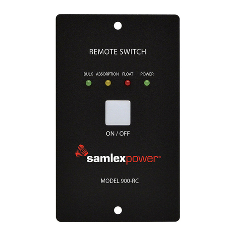
Table of contents
Other Samlexpower Remote Control manuals

Samlexpower
Samlexpower Evolution Series User manual

Samlexpower
Samlexpower EVO-RC-PLUS User manual

Samlexpower
Samlexpower 900-RC Operating and maintenance manual

Samlexpower
Samlexpower SAM-RC User manual

Samlexpower
Samlexpower 900-RC Operating and maintenance manual

Samlexpower
Samlexpower RC-300 User manual