Sammode HUYGENS SILO User manual

Sammode SA
24, rue des Amandiers –F 75020 Paris
HUYGENS SILO
Notice d'instructions
User’s guide
Gebrauchsanweisungen
II 2D Ex tD A21 IP6X TXXX

Sammode SA N° : 414 693 rév.F
24, rue des Amandiers –F 75020 Paris 2/11 Décembre 2015
Rappel des indications pour le marquage du matériel
Indications for the marking of the equipment
Angaben für die Markierung der Leuchte
-Sammode –24, rue des Amandiers –F 75020 PARIS.
-HUYGENS …W SHP
-Année de fabrication / Manufacturing year / Herstellungsjahr
-II 2D Ex tD A21 IP6X T XXX(T148°C à Ta max = 50°C)
-INERIS 01 ATEX 0021 X
-T. amb. : -20 °C / +40°C
-AVERTISSEMENTS :
« NE PAS OUVRIR SOUS TENSION »
« NE PAS OUVRIR SI UNE ATMOSPHERE EXPLOSIVE PEUT ETRE PRESENTE »
« DO NOT OPEN WHEN ENERGIZED »
« DO NOT OPEN IN CASE OF POTENTIAL EXPLOSIVE ATMOSPHERE »
« NICHT UNTER SPANNUNG ÖFFNEN »
« BEI EXPLOSIONSGEFÄHRDETER ATMOSPHÄRE NICHT ÖFFNEN »
-T° surface °C :
Projecteur
/Floodlight/
Projecktor
T. max surface
horizontale
45°
Verticale
150 W
96 °C
104 °C
106 °C
250 W
121 °C
124 °C
124 °C
400 W
125 °C
132 °C
136 °C
-Un : 230 V
-Fn : 50 Hz
-In :
Projecteur
/Floodlight/
Projecktor
In
150 W
0,80 A
250 W
1,35 A
400 W
2,00 A
-Pn :
Projecteur
/Floodlight/
Projecktor
Pn
150 W
175 W
250 W
280 W
400 W
440 W
-T câble (°C) :
Projecteur
/Floodlight/
Projecktor
T. amb. =
40 °C
T. amb. =
50 °C
150 W
/
80°C
250 W
74°C
80°C
400 W
77°C
86°C
Version Française……………………… Pages 3 à 5
English Version………………………… Pages 6 to 8
Deutsch Version………………………... Pages 9 - 11

Sammode SA N° : 414 693 rév.F
24, rue des Amandiers –F 75020 Paris 3/11 Décembre 2015
FR
Avant-propos
Les instructions qui suivent doivent être lues conjointement avec, entre autres, les normes EN 61241-14 et EN 61241-17
(Matériels électriques protégés par enveloppe - Sélection, installation et maintenance), NF C 15100, EN 60079-17
(inspection et entretien dans les emplacements dangereux), EN 60 079-19 (Réparation et révision du matériel utilisé en
atmosphères explosives), les règlements, les décrets, les arrêtés, les lois, les directives, les circulaires d’applications, les
autres normes concernées, les règles de l’art et tout autre document (édité par l’INRS ou l’INERIS, par exemple)
concernant le lieu d’installation concerné. Le non-respect de ceux-ci ne saurait engager la responsabilité de Sammode.
L’utilisateur devra avoir connaissance des risques induits par les courants électriques et des caractéristiques physiques
et chimiques des poussières présentes dans l’installation. Cela inclus, entre autres, la vérification de la compatibilité
entre les températures de surface du luminaire et les températures d’inflammation de ces poussières. Il en va de même
pour les gaz, vapeurs ou brouillards combustibles.
Ce luminaire est destiné aux zones où des atmosphères explosibles poussiéreuses peuvent être présentes :
zone 21, zone 22.
Les définitions des zones peuvent-être les suivantes :
-zone 21 : Emplacement dans lequel une atmosphère explosive sous forme d'un nuage de poussières combustibles
dans l'air est susceptible de se former occasionnellement en service normal (selon EN 61241-14).
-zone 22 : Emplacement dans lequel une atmosphère explosive sous forme d'un nuage de poussières combustibles
n'est pas susceptible de se former en service normal, et où une telle formation, si elle se produit, ne peut subsister
que pendant une courte période seulement.
La détermination et la délimitation de ces zones sont de la responsabilité et du ressort du responsable du site.
Instructions pour une mise en œuvre sans risques
(réalisée par du personnel compétent)
1 Installation
1.1 Montage du projecteur :
Après avoir préparé 3 éléments de fixation (vis par exemple).
Positionner la fourche du projecteur à l’emplacement choisi en
ayant pris soin de placer le corps du projecteur avec le PE sur le
dessous. Fixer la fourche.
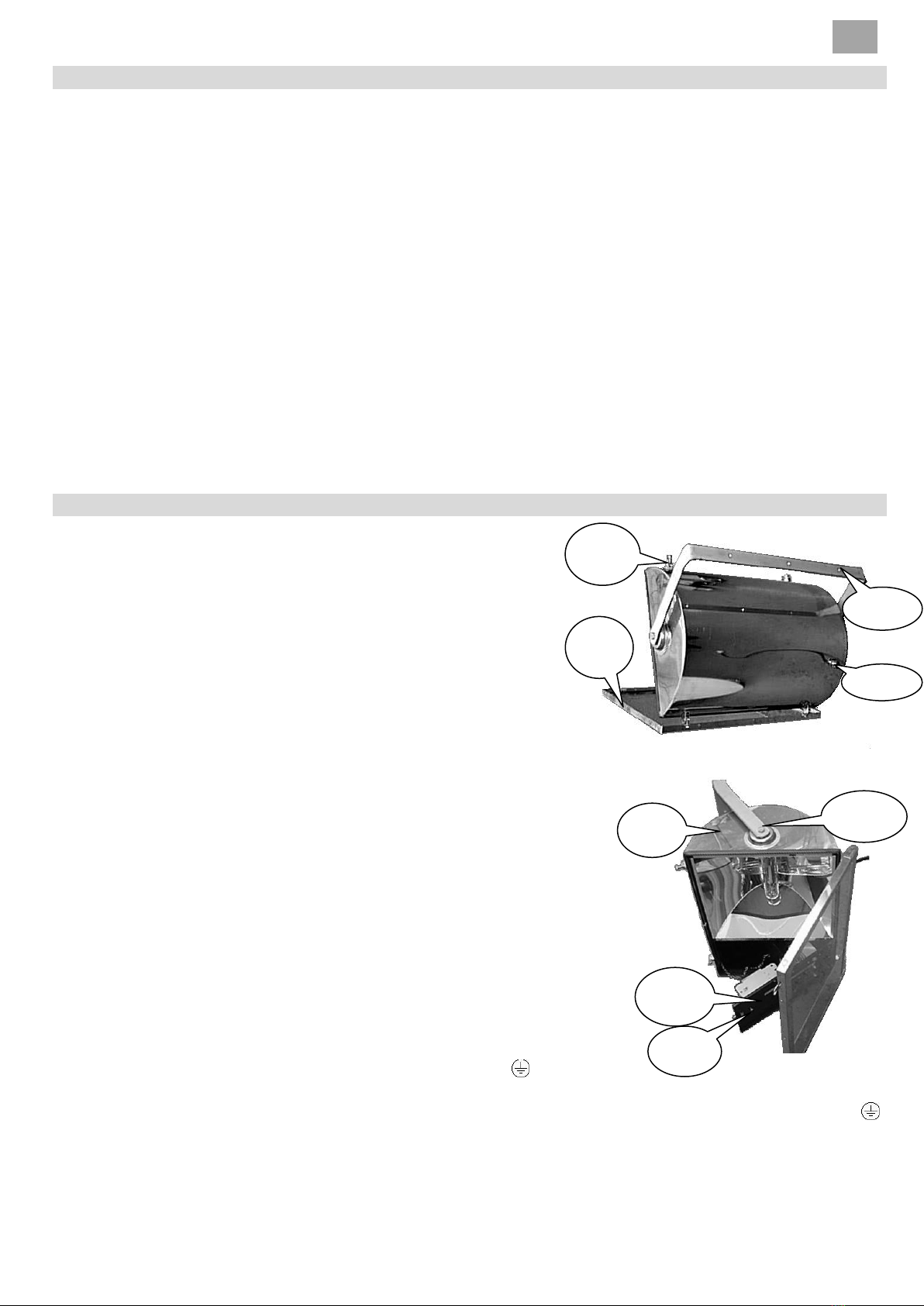
1.2 Ouverture du cadre (supportant la vitre du luminaire) :
a) dévisser les 4 vis tenant ce cadre sans les sortir de leurs axes de
fixation,
b) dégager les 2 vis en appui sur les supports ouverts,
c) faire basculer le cadre,
1.3 Ouverture de la platine appareillage :
a) à l’aide d’un tournevis plat dévisser la vis tenant la patte de verrouillage
de la platine,
b) faire basculer la platine,
c) raccorder (voir § 2),
1.4 Fermeture de la platine :
Se reporter au § 1.3 a) et au § 1.3 b) en procédant à l’inverse.
1.5 Fermeture du cadre :
Se reporter au § 1.2 en procédant à l’inverse. Les 4 vis seront serrées de
façon à assurer l’étanchéité du projecteur (les supports des vis seront en
appui sur les supports des axes de fixation de ces dernières).
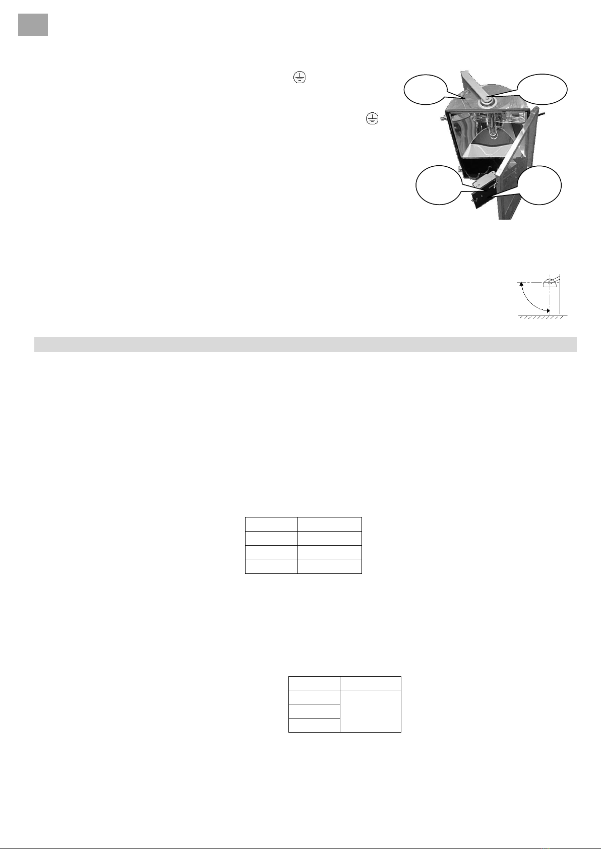
1.6 Serrer le PE (couple de 9 N.m ±1).
2. Raccordement (a effectuer hors tension)
2.1 passer le câble d'alimentation par le PE du corps sans le serrer.
2.2 raccorder la terre sur la borne de la platine prévue à cet effet .
2.3 raccorder la phase et le neutre sur les bornes du sectionneur porte-fusible prévues à cet effet (L et N).
2.4 raccorder à la terre la prise de masse (du corps à proximité du PE) prévue à cet effet (repérée par une étiquette ).
La section nominale du conducteur utilisé est définie dans les normes d’installation concernées (NF C 15-100, …).
Vis
Platine
Corps
2 vis
4 vis
Cadre
Fourche
PE

Sammode SA N° : 414 693 rév.F
24, rue des Amandiers –F 75020 Paris 4/11 Décembre 2015
FR
Rappels :
-L'alimentation secteur (230 V/50 Hz) de l'appareil doit être prise en aval du dispositif de protection du local où il
est installé.
NB :
-Compte tenu que le presse-étoupe (PE) fourni avec le luminaire est certifié ‘Ex e’ ou ‘Ex d’, il est formellement
interdit de le remplacer par un autre.
-Afin d'assurer l'herméticité prévue, le PE utilisé est prévu pour un câble rond et un seul dont le Ø extérieur est
compris entre 10 et 12 mm. Pour le choix du câble (type et section nominale), en toute situation, il faudra se
conformer aux documents d’installation concernés (NF C 15-100, …)
3. Orientation du luminaire
Afin de ne pas dépasser les températures de surface certifiées, le luminaire doit éclairer
dans une position précise telle que la face avant (vitre) est horizontale (éclairant vers le
bas) ou au plus verticale (90° de réglage), se reporter à la figure suivante :
Une fois le luminaire en position, serrer fermement (couple de 10 N.m +/- 1) les 2 vis
afin de l’y maintenir.
Cela est l’objet du § 17 (conditions spéciales pour une utilisation sûre) de l’attestation INERIS 01 ATEX 0021 X.
Maintenance (Réalisée par du personnel compétant et habitlité)
L’exploitant (l’utilisateur) doit s’assurer que les conditions d’utilisation et d’entretien sont respectées (nettoyage,
changement des lampes, remplacement des fusibles corrects, serrage des différents éléments, …).
Le non-respect de celles-ci ne saurait engager la responsabilité de Sammode.
1. Nettoyage:
Afin d’éviter les dépôts et accumulations de poussières en surface des luminaires, l’exploitant devra le nettoyer
régulièrement. Le meilleur nettoyant est une solution tiède d'eau légèrement savonneuse ou ajoutée d'un
détergent domestique doux, en utilisant un tissu doux ou une éponge pour enlever les saletés et les poussières.
Toutes les surfaces sont ensuite rincées à l'eau froide et séchées immédiatement avec un chiffon doux pour éviter
les traces de gouttes d'eau.
Ne pas utiliser d'agents nettoyants abrasifs ou à forte concentration alcaline.
2. Changement des lampes et des amorceurs :
Il doit être effectué au plus tard dès que les lampes sont défectueuses
Projecteur
Lampe SHP
150
150 W / E40
250
250 W / E40
400
400 W / E40
3. Changement de ballast:
Les ballasts ont une durée de vie de 10 ans. Au-delà de cette limite et au plus tard s’il s’avère défectueux
(brunissement, déclenchement des protections électriques, …), il devra être changé.
4. Réparation du matériel :
Elle ne peut être effectuée sans l’accord préalable écrit de Sammode.
5. Changement des fusibles
Selon le projecteur, si les fusibles déclenchent il faudra les remplacer par d’autres identiques : calibre (voir tableau
ci-contre), dimension (10 x 38) et type (gG). Auparavant, il faudra avoir déterminé l’origine du défaut et l’avoir
réparé.
Projecteur
Fusible
150
10A
250
400
orientation
+ 90 °
0 °

Sammode SA N° : 414 693 rév.F
24, rue des Amandiers –F 75020 Paris 5/11 Décembre 2015
FR
DECLARATION DE CONFORMITE
Je soussigné Rudy Bigand, Directeur technique de la société Sammode SA située au 24 rue des Amandiers 75020 PARIS
déclare que les luminaires suivants (groupe IIIC catégorie 2D) :
-HUYGENS 150 pour 1 lampe SHP 150 Watts / Classe 1 / 230 Volts - 50Hz
-HUYGENS 250 pour 1 lampe SHP 250 Watts / Classe 1 / 230 Volts - 50Hz
-HUYGENS 400 pour 1 lampe SHP 400 Watts / Classe 1 / 230 Volts - 50Hz
sont conformes aux exigences réglementaires suivantes :
Directive sur la compatibilité électromagnétique (CEM) 2014/30/UE
Pour garantir sa conformité le produit répond aux normes spécifiques aux appareils d'éclairages EN 55015 relatif aux
méthodes de mesures et EN61547 concernant l'immunité. Par ailleurs les composants actifs sont eux-mêmes
conforme à la directive CEM
Directive basse tension (DBT) 2006/95/CE du 12 décembre 2006
Pour garantir sa conformité le produit répond aux normes luminaires de la série EN 60598, les composants actifs
étant eux-mêmes conformes à la DBT.
Tous les appareils sortant de montage font l'objet d'essais de fonctionnement et de sécurité, en particulier la rigidité
diélectrique et la continuité de terre.
Décret N°2005-829 du 22 juillet 2005
La Directive 2011/65/CE (relative à la limitation de l’utilisation de certaines substances dangereuses dans les
équipements électriques et électroniques) et la directive 2012/19/UE (relative aux déchets d’équipements
électriques et électroniques).
Directive ATEX 94/9/EC du 23 mars 1994
Pour garantir sa conformité le produit répond aux normes suivantes :
-EN 60079-0:2012/A11 :2013 (Matériel électrique pour atmosphères explosives –Règles générales),
-EN 60079-31:2014 (Atmosphères explosives - Partie 31 : Protection du matériel contre l'inflammation des
poussières par enveloppe "t").
-Au type ayant fait l'objet de l'attestation d'examen CE de type n° INERIS 01 ATEX 0021X délivrée par l’INERIS,
n° 0080, F-60 550 Verneuil-en-Halatte.
Paris le 18 décembre 2015
RUDY BIGAND
Directeur technique
L’organisme, notifié intervenant dans la phase de contrôle de la production ou du produit est : INERIS, n° 0080, F-
60550 Verneuil-en-Halatte.

Sammode SA N° : 414 693 rév.F
24, rue des Amandiers –F 75020 Paris 6/11 Décembre 2015
EN
Foreword
The following instructions must be read, among others, together with the Standards EN 61241-14 and EN 61241-17
(Electrical apparatus protected by enclosures - Selection, installation and maintenance), EN 60079-17 (Inspection and
maintenance of electrical installations in hazardous areas), EN 60079-19 (Repair and overhaul for apparatus used in
explosive atmospheres), the by-laws, decrees, orders, laws, directives, implementation circulars, other relevant
standards, state of the art and any other document regarding the relevant installation site. Sammode cannot and will
not be liable if these standards are not complied with. The user shall be fully aware of the electrical hazards as well as
the physical and chemical characteristics of the dusts to be found in the installation. This shall include, among others,
the checking of the compatibility between the surface temperatures of the luminaire and the ignition temperatures of
these dusts in particular. The same applies to combustible gas, vapours or mists.
This luminaire is meant for areas where potentially explosive dust atmospheres may be present:
Area 21, Area 22
These area definitions may be as follows:
-Area 21: Location where an explosive atmosphere, taking the form of a combustible dust cloud in the air, is liable
to occasionally gather under normal operating conditions (according to EN 61241-14).
-Area 22: Location where an explosive atmosphere in the form of a cloud of combustible dust is not likely to occur
in normal operation, and where such training, if it occurs, can only exist for a short period only.
Determination and delimitation of these areas fall within the responsibility and competence of the person in charge of
the site.
Instructions for a hazard-free installation (to be carried out by trained staff)
1 Installation
Any work on the luminaire should be carried out when voltage is off.
1.1 Mounting the projector:
After preparing 3 fasteners (eg screws). Position the mounting
bracket of the projector at the location chosen with care taken to
place the projector body with the cable gland on the underside. Set
the mounting bracket.
1.2 Open frame (supporting the glass fitting):
a) Unscrew the 4 screws holding this part without leaving
their areas of attachment,
b) identify the 2 screws resting on supports open
c) connection,
1.3 Opening of the gear tray:
a) Using a screwdriver unscrew the screw holding the locking tab of the plate,
b) make the gear tray switch,
c) connect (see § 2),
1.4 Closing the gear tray:
Refer to § 1.3 a) and § 1.3 b) by doing the opposite.
1.5 Closing the connection:
Refer to § 1.2 by taking the inverse. The 4 screws are tightened to
ensure the tightness of the projector (the media screws are supported
on the supports of the axis of fixing them).
1.6 Tighten the cable gland (9 n.m torque ±1).
2. Connection
To be carried out when power is off
2.1 pass the power cable through the cable gland loosely.
2.2 connect the earth terminal on the gear tray ( ).
2.3 connect the live and neutral terminals of the connector fuse holder (L and N).
2.4 connect to earth connection on the metallic casing (identified by a label ). The nominal section of the wires used
is defined in the relevant installation standards
screws
Gear Tray
Casing
2 screws
4 screws
Frame
mounting
bracket
Cable gland

Sammode SA N° : 414 693 rév.F
24, rue des Amandiers –F 75020 Paris 7/11 Décembre 2015
EN
Reminder
The mains (230 V/50 Hz) of the device must be taken downstream of the protection of the premises where it is
installed.
NB:
- Given that the gland (PE) supplied with the luminaire is certified Ex e 'or Ex d', it is forbidden to replace it with
another.
- To ensure the tightness under the EP is expected to use a round cable and one whose outer diameter is between
10 and 12 mm. For the choice of cable (type and nominal section) in any situation, it must comply with installation
documents concerned.
3. Position of the luminaire
In order not to exceed the certified surface temperatures, the luminaire has to be
installed with precise positions (see the darwing)
Please refer to § 17 of attestation INERIS 01 ATEX 0021 X
Maintenance (To be carried out by trained and duly approved staff)
The user should make sure that the conditions of use and maintenance are complied with (cleaning, replacement of
lamps, replacement with appropriate fuses, tightening of the various components, etc.).
SAMMODE cannot be held responsible should these instructions not be complied with.
1. Cleaning :
In order to avoid deposits and accumulations of dust on the surface of the luminaires, the user should clean them
regularly. The most appropriate way to clean them is the use a lukewarm, soapy water solution or water with a soft
household cleaning product, using a soft cloth or sponge to remove the dirt and dust. All the surfaces must then be
rinsed with cold water and dried immediately with a soft cloth to avoid water drop traces.
Do not use any abrasive cleaning agents or cleaning products with high alkaline concentration.
2. Lamps replacement :
Lamps should be replaced as soon as they are faulty.
Floodlight
Lamp SHP
150
150 W / E40
250
250 W / E40
400
400 W / E40
3. Ballast replacement :
The ballasts have a lifespan of 10 years. Beyond this limit and not later if it proves faulty (browning, triggering electrical
protection...), it should be changed
4. Repair of the unit:
The repair of the unit cannot be undertaken without Sammode’s prior consent in writing
5. Change fuses
According to the projector, if it will trigger fuses replaced by other identical size (see table cons), size (10 x 38) and
type (gG). Previously, he must have determined the defect and be repaired.
Floodlight
Fuse
150
10 A
250
400
orientation
+ 90 °
0 °

Sammode SA N° : 414 693 rév.F
24, rue des Amandiers –F 75020 Paris 8/11 Décembre 2015
EN
CONFORMITY DECLARATION
I undersigned Rudy Bigand, Technical Director of the company Sammode SA, located at 24 rue des Amandiers 75020
PARIS, declares that following products (group IIIC category 2D) :
-HUYGENS 150 pour 1 lampe SHP 150 Watts / Classe 1 / 230 Volts - 50Hz
-HUYGENS 250 pour 1 lampe SHP 250 Watts / Classe 1 / 230 Volts - 50Hz
-HUYGENS 400 pour 1 lampe SHP 400 Watts / Classe 1 / 230 Volts - 50Hz
meet the following regulatory requirements:
ElectroMagnetic compatibility Directive (EMC) 201/30/UE
To ensure compliance the product meets specific standards lighting fixtures: EN 55015 relating to radio disturbance
and EN 61547 on immunity. Moreover, the active components are themselves in conformity with the EMC Directive
Low Voltage Directive (LVD) 2006/95/EC of 12 December 2006
To ensure compliance the product meets the standards of fixtures series EN 60598, the active components are
themselves consistent with the LVD.
All equipment leaving the assembly shall be test operation and safety, especially dielectric and earthing continuity.
Decree No. 2005-829 of 22 July 2005
Directives 2011/65/UE (on the restrictions on the use of certain hazardous substances in Electrical and Electronic
Equipment) Directive 2012/19/UE and (Known as WEEE, Waste Electrical and Electronic Equipment).
ATEX Directive 94/9/EC of 23 mars 1994
To ensure compliance the product meets the followings standards:
-EN 60079-0:2012/A11 :2013 (Explosive Atmospheres - Equipment –General requirements),
-EN 60079-31 : 2014 (Explosive atmospheres - Part 31: Equipment dust ignition protection by enclosure "t")
- The EC-type examination certificate INERIS 01 ATEX 0021X delivered by the notified body
INERIS, 0080, F-60 550 Verneuil-en-Halatte.
Paris 18 December 2015
RUDY BIGAND
Technical Director
The notified body involved in the production control stage, or the product itself is : INERIS, n° 0080, F-60550 Verneuil-
en-Halatte.

Sammode SA N° : 414 693 rév.F
24, rue des Amandiers –F 75020 Paris 9/11 Décembre 2015
DE
Vorwort
Folgende Gebrauchsanweisungen sollten mindestens zusammen mit den französischen Normen EN 61241-14 und
EN 61241-17 (Durch Gehäuse geschützte elektrische Betriebsmittel - Auswahl, Installation und Wartung), EN 60079-17
(Inspektion und Wartung an gefährlichen Aufstellorten), EN 60079-19 (Instandhaltung und Wartung der in
explosionsgefährdeten Atmosphären eingesetzten Leuchte), die Regelungen, Verordnungen, Erlasse, Gesetze,
Richtlinien, Anwendungsrundschreiben, weitere bezügliche Normen, die Regeln der Kunst sowie jede weitere
Unterlage dem Installationsort bezüglich. Bei Nichtbeachtung der hier oben angegebenen Unterlagen kann und wird
Sammode keine Haftung tragen. Der Benutzer sollte die elektrischen Gefahren sowie die physikalischen und
chemischen Eigenschaften des Staubs am Ort der Installation kennen. Das heißt unter anderem die Überprüfung der
Kompatibilität zwischen den Temperaturen an der Oberfläche der Leuchte und den Zündtemperaturen des Staubs.Dies
gilt auch für brennbare Stoffe wie Gas, Dampf oder Nebel.
Diese Leuchte ist für Atmosphären geeignet, die explosiven Staub enthalten können:
Zone 21, Zone 22
Die Zonen können wie folgt bestimmt werden:
-Zone 21: Ort, an dem sich eine explosionsgefährdete Atmosphäre, in der Form einer brennbaren Staubwolke in
der Luft, unter normalen Bedingungen eventuell ergeben kann (nach EN 61241-14).
-Zone 22 : Ort, an dem eine explosionsfähige Atmosphäre in Form einer Wolke aus brennbarem Staub sind
wahrscheinlich nicht im normalen Betrieb auftreten, und wenn eine solche Ausbildung, wenn sie auftritt, kann nur
für einen kurzen Zeitraum nur existieren.
Für die Bestimmung und Festlegung dieser Zonen trägt die für den Ort verantwortliche Person Haftung.
Anweisungen für eine gefahrlose Installation
(Die Installation sollte nur durch trainiertes Personal ausgeführt werden)
1 Installation
Vor Arbeitsanfang sollte die Leuchte ausser Spannung
gesetzt werden.
1. Installation :
1.1. Montagevorrichtung:
Nach der Herstellung von 3 Verbindungselemente (zB
Schrauben). Legen Sie die Montagehalterung aus den
Projektor auf die Lage mit Sorge getragen, den Projektor
mit Drüse an der Unterseite Ort gewählt. Befestigen Sie die
Halteklammer auf.
1.2 Open Frame (Unterstützung der Glas-Befestigung):
a) Lösen Sie die 4 Schrauben an diesem Teil, ohne ihren
Gebieten von Pfändung,
b) die 2 Schrauben ruht auf Stützen öffnen
c) Um die Einstellung zu wechseln,
1.3 Open Deckausrüstung:
a) Mit einem Schraubenzieher schrauben Sie die Schraube, mit der Die Verriegelung der Platte,
b) die-Platte,
c) in Verbindung zu treten (siehe § 2),
1,4 Schließen Sie die Platte:
Wenden Sie sich an § 1.3 a) und § 1.3 b), indem er das Gegenteil.
1,5 Schließen Sie die Verbindung:
Wenden Sie sich an § 1.2, indem man die inverse. Die 4 Schrauben werden festgezogen werden, um die Dichtheit
des Projektors zu gewährleisten (die Medien Schrauben sind auf den Trägern der wichtigsten
Befestigungsschrauben unterstützt wird).
1,6 Ziehen Sie die Kabelverschraubung (9 n.m Drehmoment ±1).
4
schraube
Rahmen
Montagew
inkel
Kabelverschr
aubung

Sammode SA N° : 414 693 rév.F
24, rue des Amandiers –F 75020 Paris 10/11 Décembre 2015
DE
2 Anschluss (Ohne Netzanschluß vornehmen)
2,1 ändern Sie das Kabel Feeding the Kabelverschraubung Körper locker.
2,2 Verbindung der Erde Terminal auf dem Plattenteller ( ).
2,3 Verbinden Sie den Phase und Nullleiter Terminals der Trennschalter-
Sicherungshalter (L und N).
2,4 Anschluss an Land machen Körper (durch ein Etikett gekennzeichnet ).
Die nominelle Nummer der verwendeten Treiber ist in den einschlägigen
Normen definiert Installation
Erinnert sich:
- Das Netz (230 V/50 Hz) des Gerätes muss darauf geachtet werden, hinter dem
Schutz der Räumlichkeiten, in denen es installiert ist.
NB:
- Da die Drüse (Kabelverschraubung) mit der Leuchte geliefert wird zertifiziert
Ex e oder Ex d, ist es verboten, ihn durch einen anderen ersetzen.
- Um die Dichtheit im Rahmen der Kabelverschraubung sicherzustellen, wird erwartet, dass ein rundes Kabel und ein,
deren Außendurchmesser Nutzung liegt zwischen 10 und 12 mm. Für die Wahl der Kabel (Typ und der nominalen
Absatz) in jeder Situation
3. Ausrichtung der Beleuchtung
Um nicht Oberflächentemperaturen zertifiziert überschreiten, muss die Beleuchtung eine
genaue Position zu beleuchten
Bitte beachten Sie § 17 der Bescheinigung INERIS 01 ATEX 0021 X
Wartung (Sollte nur durch trainiertes Personal ausgeführt warden.)
Der Benutzer sollte sichern, dass die Gebrauchs- und Wartungsbedingungen beachtet werden (Reinigung, Ersetzen der
Leuchtmittel, Ersetzen der durchgebrannten Sicherung mit geeigneten Sicherungen, Anziehen der verschiedenen
Komponente, usw.).
Bei Nichtbeachtung der hier oben angegebenen Unterlagen kann und wird Sammode keine Haftung tragen.
1. Reinigung :
Die Leuchte sollte regelmässig gereinigt werden, um Staubablagerung an der Oberfläche zu vermeiden. Am besten wird
die Leuchte mit einem Staubtuch oder einem Schwamm anhand einer seifenhaltigen Wasserlösung oder Wasser mit
einem üblichen sanften Reiniger. Allen Oberflächen sollten dann mit Kaltwasser nachgespült und sofort mit einem
sanften Tuch getrocknet werden, um Tropfenspuren zu vermeiden.
In keinem Fall dürfen scheuernde Reinigungsprodukte oder Reiniger mit alkalischer Lösung verwendet werden.
2 Ersetzen von Leuchtmitteln:
Die Leuchtmittel sind zu ersetzen, sobald sie fehlerhaft sind.
Projecktor
Lamp SHP
150
150 W / E40
250
250 W / E40
400
400 W / E40
3. Ersetzen von Leuchtmitteln :
Die Vorschaltgeräte haben eine Lebensdauer von 10 Jahren. Jenseits dieser Grenze und nicht später, wenn er
nachweist, fehlerhaft (Bräunung, ausgelöst elektrischen Schutz, ...), es sollte geändert werden.
4. Reparatur der Leuchte:
Die Reparatur der Leuchte kann nicht ohne die vorige schriftliche Genehmigung von Sammode vorgenommen werden.
5. Ändern Sicherungen :
Projecktor
Sicherung
150
10 A
250
400
schraube
Gerätesteg
Gehäuse
2 schraube
orientation
+ 90 °
0 °

Sammode SA N° : 414 693 rév.F
24, rue des Amandiers –F 75020 Paris 11/11 Décembre 2015
DE
EG-KONFORMITÄTSERKLÄRUNG
Der Unterzeichnende, Rudy Bigand, technischer Leiter von SAMMODE SA mit Firmensitz in der 24 rue des Amandiers
75020 PARIS, erklärt hiermit, dass die folgenden Leuchten (Gerätegruppe IIIC Kategorie 2D):
-HUYGENS 150 / 1 lampe SHP 150 Watts / SK I / 230 Volts - 50Hz
-HUYGENS 250 / 1 lampe SHP 250 Watts / SK I / 230 Volts - 50Hz
-HUYGENS 400 / 1 lampe SHP 400 Watts / SK I / 230 Volts - 50Hz
konform sind mit folgenden gesetzlichen Bestimmungen:
Richtlinie über die elektromagnetische Verträglichkeit (EMV) 2014/30/UE vom 15. Dezember 2004
Zur Gewährleistung der Konformität entspricht das Produkt den spezifischen Normen für
Beleuchtungseinrichtungen: EN 55015 über Messverfahren und EN 61547 über EMV-Störfestigkeits-anforderungen.
Darüber hinaus sind die aktiven Bauelemente ebenfalls konform mit der EMV-Richtlinie.
Niederspannungsrichtlinie 2006/95/EG vom 12. Dezember 2006
Zur Gewährleistung der Konformität entspricht das Produkt den Leuchtennormen der Serie EN 60 598, wobei die
aktiven Bauelemente der Niederspannungsrichtlinie entsprechen.
Sämtliche Geräte werden nach dem Zusammenbau Funktions- und Sicherheitstests unterzogen, insbesondere im
Hinblick auf die Durchschlagfestigkeit und die Erdung.
Erlass Nr. 2005-829 vom 22. Juli 2005
Umsetzung der Richtlinie 2011/65/UE (die sogenannte RoHS über die Beschränkung der Verwendung bestimmter
gefährlicher Stoffe in Elektro- und Elektronikgeräten) sowie der Richtlinie 2012/19/UE (die sogenannte WEEE über
Elektro- und Elektronikgeräte-Abfall).
ATEX-Produktrichtlinie 94/9/EG vom 23. März 1994
Zur Gewährleistung der Konformität entspricht das Produkt folgenden Normen:
-EN 60079-0:2012/A11 :2013 (Elektrische Betriebsmittel für explosionsfähige Atmosphäre –Allgemeine
Regeln),
-EN 60079-31 : 2014 (Explosionsfähige Atmosphäre Teil 31: Geräte-Staubexplosionsschutz durch Gehäuse "t“)
-Dem Typ, der Gegenstand der EG-Baumusterprüfbescheinigung Nr. INERIS 01 ATEX 0021X ist, ausgestellt von
INERIS, Nr. 0080, F-60 550 Verneuil-en-Halatte.
Paris, den 18 décembre 2015
RUDY BIGAND
Technischer Leiter
Benannte Stelle für die Produktions- oder Produktkontrolle: INERIS, Nr. 0080, F-60550 Verneuil-en-Halatte
Table of contents
Languages:
Other Sammode Lantern manuals