Chapter
1
Hardware Description
1.3
The
AM
9513
Counter Chip
The AM 9513 counter chip contains five high-speed counters
which can be programmed to perform various counting and
scaling functions. A general description for each of the 16-bit
registers that control these counters is given below.
1.3.1 Master Mode Register (AM 9513)
The MasterModeregister(MM) is usedto enableand perform
special functions which are common to each individual
counter.Thereisonemastermoderegisterforallfivecounters.
These functions include:
W
Definingandenablingtheinputs,outputs,andscalingfactor
for Scaler
2.
This is the main function of the MM register
W
Providing an enable bit for the output of Scaler 2. The
output of Scaler 2 will be referredto as FOUT
W
Providing enable bits for the two comparators that are
availablefor Counters1and
2
Providing a bit to select the operating mode of Scaler
2.
Either binaryscaling or BCD scaling is allowed
B
Providing two bits which are used to control and enable
the real-timeclockfunction
1.3.4 Hold Register (AM 9513)
There is one Hold register (H) for each of the five counters.
The Hold register is used as a storage buffer for the counter
value. The contents of the counter will be transferred to the
Holdregistervia a software command. Thisfeature allowsthe
user to check the current value of the counter without
interrupting the counting operation.,
The Hold register cannot be read directly; its data is first
transferred to the result of counter register. You must then
readthe result of counter register to retrieve the value stored
inthe Hold register.The resultof Counterregisterisdescribed
in Section 1.5.1.
1.3.5 Alarm Register (AM 9513)
There are two Alarm registers (A); one for Counter
1,
and one
for Counter 2. The Alarm register is used in conjunction with
the comparators available to Counters 1 and 2. The Alarm
register.is used to store the value which will be compared
with the counter value. If the comparator is enabled in the
Master Mode register, the output of the counter will become
active only when the Alarm-registervalue equals the counter
value. The Alarm register may also be referred to as the
Interruptregister.
1.3.2 Counter Mode Register (AM 9513)
There is one Counter Mode register (CM) for each of the five
1-4
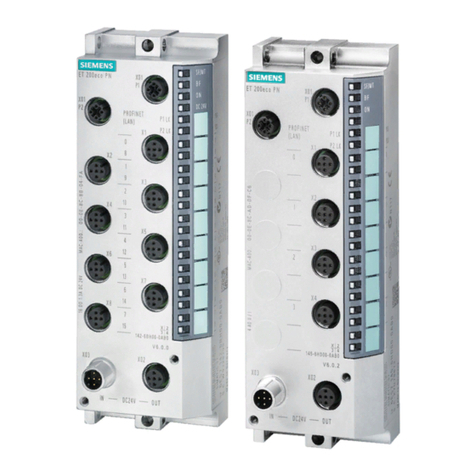
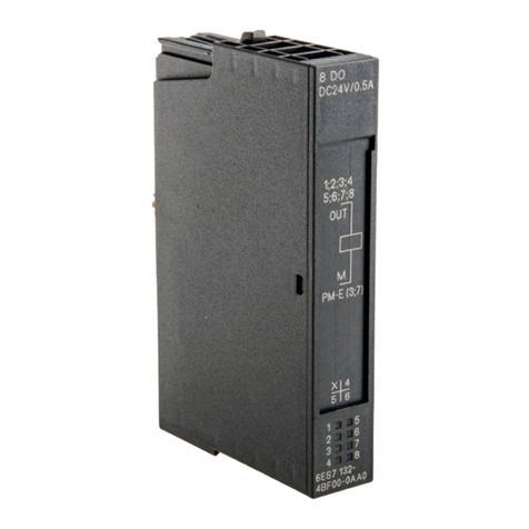
6ES5-242
Module Registers
counters. The counter mode registers are used to provide The 6~~5-242module has several registers which are not
control, setup, and operation of each individual counter. found in the AM 9513 or the AM 9519 chips. These registers
These functions include: are usedfor various functions which are not available on the
W
Providing four bits to select one of 16 available pulse AM 9513 or the AM 9519, but are necessaryfor the operation
sources to the counter of the AM 9519, but are necessary for the operation of the
W
Providingabittoenableordisablethegatecontrolfunctions module. A brief description of these registers is presented.
W
Providing three bits to select the operating mode of the
1-4.1mntrOl~~~i~t~~
aate controlfunction
-
TheControlregister(CTRL) isusedtocontrolvariousfunctions
Providing a bit to select the counting pulse edge, either
and
counter
selections
of
the
AM
9513. This
register
is
not
rising or falling edge
+@
normally addressed directly by the user; the function blocks
W
Providing a bit to select one of two registers from which used to communicate with the 6ES5-242 module will handle
the counter value can be loaded any data transfers to this register.These functions include:
W
Providinga bitto select one of two counting modes, either
W
Providingthree bits to select from one of eight possible
continuous or onecycle mode chip operations which include: parameter assignment,
W
Providingabittoselectthecounter's operatingmode,either counter manipulation,andselection of additionalfunctions.
binary or BCD counting
W
Providing five bits, one for each counter, which are used
Providing a bit to select the counting direction, either up
counting or down counting. to specify which counter or counters are to be involvedin
theoperationselected bytheotherthreebitsof theregister.
W
Providing three bits to select the output configuration of
the counter
1.4.2 Function Number Register
The Function Number Register (FNR) is used to identify the
1.3.3 Load Register (AM 9513)
user-stored functions. These functions can be stored on a
4K
byte EPROM.
There is one Load register (L) for each of the five counters.
The Load register is usedto providethe counter with a preset
count value which isset by the user.
