manuals.online logo
Brands
  1. Home
  2. •
  3. Brands
  4. •
  5. Samsung
  6. •
  7. LCD TV
  8. •
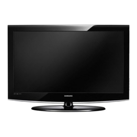
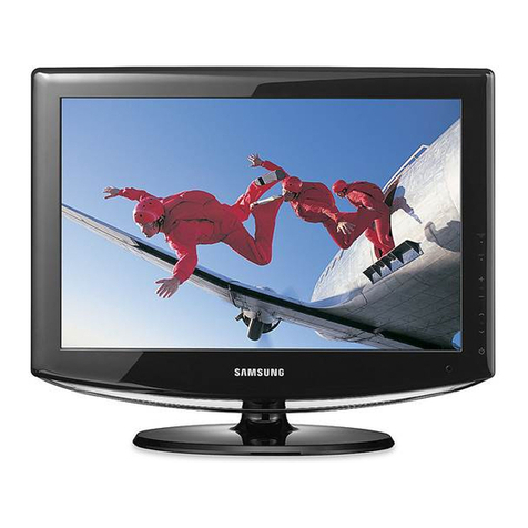
  9. Samsung LT-P326W User manual

Samsung LT-P326W User manual

BN68-00653A-01
1-800-SAMSUNG(1-800-726-7864)
U.S.A
Samsung Electronics America
Service Division
400 Valley Road, Suite 201
Mount Arlin ton, NJ 07856
www.samsun usa.com
Canada
Samsung Electronics Canada Inc.
Samsung Customer Care
7037 Financial Drive
Mississau a, Ontario
L5N 6R3
www.samsun .ca
LT-P326
This device is a Class B digital apparatus.
BN68-00653A-01Eng-00COVER 5/7/04 9:57 AM Page 1
Contents 1
CONTENTS
Chapter 1: Your New TV
List of Features . . . . . . . . . . . . . . . . . . . . . . . . . . . . . . . . . . . . . . . . 1
List of Parts . . . . . . . . . . . . . . . . . . . . . . . . . . . . . . . . . . . . . . . . . . . 1
Familiarizing Yourself with Your New TV . . . . . . . . . . . . . . . . . . . . 2
ight-side Panel Buttons . . . . . . . . . . . . . . . . . . . . . . . . . . . . . . 2
ear Panel Jacks . . . . . . . . . . . . . . . . . . . . . . . . . . . . . . . . . . . . 3
emote Control . . . . . . . . . . . . . . . . . . . . . . . . . . . . . . . . . . . . . . . . 4
Installing Batteries in the emote Control . . . . . . . . . . . . . . . . . . . . 6
If remote control doesn’t work . . . . . . . . . . . . . . . . . . . . . . . . . . . . . 6
Chapter 2: Installation
Connecting VHF and UHF Antennas . . . . . . . . . . . . . . . . . . . . . . . . 7
Antennas with 300-ohm Flat Twin Leads . . . . . . . . . . . . . . . . . 7
Antennas with 75-ohm ound Leads . . . . . . . . . . . . . . . . . . . . 8
Separate VHF and UHF Antennas . . . . . . . . . . . . . . . . . . . . . . . 8
Connecting Cable TV . . . . . . . . . . . . . . . . . . . . . . . . . . . . . . . . . . . . 8
Cable without a Cable Box . . . . . . . . . . . . . . . . . . . . . . . . . . . . 8
Connecting to a Cable Box that Descrambles All Channels . . . . 9
Connecting to a Cable Box that Descrambles Some Channels . . 9
Connecting HDMI . . . . . . . . . . . . . . . . . . . . . . . . . . . . . . . . . . . . . 11
How to connect Core . . . . . . . . . . . . . . . . . . . . . . . . . . . . . . . . . . . 11
Connecting a VC . . . . . . . . . . . . . . . . . . . . . . . . . . . . . . . . . . . . . 12
Connecting an S-VHS VC . . . . . . . . . . . . . . . . . . . . . . . . . . . . . . 13
Connecting a DVI-D Cable . . . . . . . . . . . . . . . . . . . . . . . . . . . . . . . 13
Connecting a DVD Player . . . . . . . . . . . . . . . . . . . . . . . . . . . . . . . 14
Connecting a Digital TV Set-Top Box . . . . . . . . . . . . . . . . . . . . . . 14
Connecting a PC . . . . . . . . . . . . . . . . . . . . . . . . . . . . . . . . . . . . . . . 14
ANYNET . . . . . . . . . . . . . . . . . . . . . . . . . . . . . . . . . . . . . . . . . . . . 16
What is the Anynet . . . . . . . . . . . . . . . . . . . . . . . . . . . . . . . . . 16
Anynet . . . . . . . . . . . . . . . . . . . . . . . . . . . . . . . . . . . . . . . . . . 17
Connecting TV + DVD/VC Combo:
Connecting AV Signal Cables . . . . . . . . . . . . . . . . . . . . . . . . . 18
C
onnecting TV + DVD eceiver: Connecting AV Signal Cables
. 19
Connecting TV + DVD Combo + DVD eceiver:
Connecting AV Signal Cables . . . . . . . . . . . . . . . . . . . . . . . . . 20
Chapter 3: Operation
Turning the TV On and Off . . . . . . . . . . . . . . . . . . . . . . . . . . . . . . 21
Changing Channels . . . . . . . . . . . . . . . . . . . . . . . . . . . . . . . . . . . . . 21
Using the Channel Buttons . . . . . . . . . . . . . . . . . . . . . . . . . . . 21
Using the Pre-CH Button to select the Previous Channel . . . . . 21
Adjusting the Volume . . . . . . . . . . . . . . . . . . . . . . . . . . . . . . . . . . . 21
Using Mute . . . . . . . . . . . . . . . . . . . . . . . . . . . . . . . . . . . . . . . 21
Viewing the Display . . . . . . . . . . . . . . . . . . . . . . . . . . . . . . . . . . . . 22
Viewing the Menus . . . . . . . . . . . . . . . . . . . . . . . . . . . . . . . . . . . . . 22
Setting Up Your emote Control . . . . . . . . . . . . . . . . . . . . . . . . . . 23
emote Control Codes . . . . . . . . . . . . . . . . . . . . . . . . . . . . . . . . . . 26
Chapter 4: Special Features
Plug & Play Feature . . . . . . . . . . . . . . . . . . . . . . . . . . . . . . . . . . . . 27
Memorizing the Channels . . . . . . . . . . . . . . . . . . . . . . . . . . . . . . . . 28
Selecting the Video Signal-source . . . . . . . . . . . . . . . . . . . . . . 28
Storing Channels in Memory (Automatic Method) . . . . . . . . . 29
Adding and Erasing Channels (Manual Method) . . . . . . . . . . . 30
Labeling Channels . . . . . . . . . . . . . . . . . . . . . . . . . . . . . . . . . . . . 30
To set-up your Favorite Channels . . . . . . . . . . . . . . . . . . . . . . . . . . 31
To Select Source . . . . . . . . . . . . . . . . . . . . . . . . . . . . . . . . . . . . . . . 31
To Edit the Input Source Name . . . . . . . . . . . . . . . . . . . . . . . . . . . . 32
BN68-00653A-01Eng.qxd 5/7/04 9:03 AM Page 1
Contents 2
CONTENTS
Using Automatic Picture Settings . . . . . . . . . . . . . . . . . . . . . . . . . . 33
Customizing the Picture . . . . . . . . . . . . . . . . . . . . . . . . . . . . . . . . . 34
Using Automatic Sound Settings . . . . . . . . . . . . . . . . . . . . . . . . . . 35
Customizing the Sound . . . . . . . . . . . . . . . . . . . . . . . . . . . . . . . . . . 36
Selecting a Menu Language . . . . . . . . . . . . . . . . . . . . . . . . . . . . . . 37
Setting the Blue Screen Mode . . . . . . . . . . . . . . . . . . . . . . . . . . . . . 38
Fine Tuning Channels . . . . . . . . . . . . . . . . . . . . . . . . . . . . . . . . . . . 39
LNA (Low Noise Amplifier) . . . . . . . . . . . . . . . . . . . . . . . . . . . . . . 40
Viewing Picture-in-Picture . . . . . . . . . . . . . . . . . . . . . . . . . . . . . . . 41
Activating Picture-in-Picture . . . . . . . . . . . . . . . . . . . . . . . . . . 41
Selecting a Signal Source (External A/V) for PIP . . . . . . . . . . 42
Swapping the Contents of the PIP and Main image . . . . . . . . . 42
Changing the PIP Channel . . . . . . . . . . . . . . . . . . . . . . . . . . . 42
Changing the Location of the PIP Window . . . . . . . . . . . . . . . 42
Changing the Size of the PIP Window . . . . . . . . . . . . . . . . . . . 42
DNIe(Digital Natural Image engine) . . . . . . . . . . . . . . . . . . . . . . . . 43
MCC (My Color Control) . . . . . . . . . . . . . . . . . . . . . . . . . . . . . . . . 44
Easy Control . . . . . . . . . . . . . . . . . . . . . . . . . . . . . . . . . . . . . . 44
Detail Control . . . . . . . . . . . . . . . . . . . . . . . . . . . . . . . . . . . . . 45
I2C (Intelligent Image Control) . . . . . . . . . . . . . . . . . . . . . . . . . . . 46
IBC (Intelligent Brightness Control) . . . . . . . . . . . . . . . . . . . . . . . . 47
Changing the Screen Size. . . . . . . . . . . . . . . . . . . . . . . . . . . . . . . . 48
Freezing the Picture . . . . . . . . . . . . . . . . . . . . . . . . . . . . . . . . . . . . 48
Adjusting the Color Tone . . . . . . . . . . . . . . . . . . . . . . . . . . . . . . . . 49
Setting the TruSurround XT(S S TSXT) . . . . . . . . . . . . . . . . . . . . 50
Automatic Volume Control . . . . . . . . . . . . . . . . . . . . . . . . . . . . . . 51
Special Sound Options . . . . . . . . . . . . . . . . . . . . . . . . . . . . . . . . . . 52
Adjusting the Headphone Sound . . . . . . . . . . . . . . . . . . . . . . . . . . 53
Selecting the Main or Sub Sound . . . . . . . . . . . . . . . . . . . . . . . . . . 54
Sub Woofer . . . . . . . . . . . . . . . . . . . . . . . . . . . . . . . . . . . . . . . . . . 55
Setting the Clock . . . . . . . . . . . . . . . . . . . . . . . . . . . . . . . . . . . . . 56
Setting the On/Off Timer . . . . . . . . . . . . . . . . . . . . . . . . . . . . . . . . 57
Setting the Sleep Timer . . . . . . . . . . . . . . . . . . . . . . . . . . . . . . . . . 59
Viewing Closed Captions . . . . . . . . . . . . . . . . . . . . . . . . . . . . . . . . 60
Using the V-Chip . . . . . . . . . . . . . . . . . . . . . . . . . . . . . . . . . . . . . . 62
Color Weakness . . . . . . . . . . . . . . . . . . . . . . . . . . . . . . . . . . . . . . . 68
Selecting the Melody . . . . . . . . . . . . . . . . . . . . . . . . . . . . . . . . . . . 69
Chapter 5: PC isplay
Using Your TV as a Computer (PC) Display . . . . . . . . . . . . . . . . . . 70
How to Set up Your PC Software (Windows only) . . . . . . . . . 70
How to Auto Adjust . . . . . . . . . . . . . . . . . . . . . . . . . . . . . . . . 71
Adjusting the Screen Quality . . . . . . . . . . . . . . . . . . . . . . . . . 72
Changing the Screen Position . . . . . . . . . . . . . . . . . . . . . . . . . 73
To Initialize the Screen Position or Color Settings . . . . . . . . . . 74
Chapter 6: Troubleshooting
Identifying Problems . . . . . . . . . . . . . . . . . . . . . . . . . . . . . . . . . . . 75
Appendix
Installing the Stand . . . . . . . . . . . . . . . . . . . . . . . . . . . . . . . . . . . . . 82
Wall Mount Installation Guide . . . . . . . . . . . . . . . . . . . . . . . . . . . . 83
Cleaning and Maintaining Your TV . . . . . . . . . . . . . . . . . . . . . . . . . 85
Using Your TV in Another Country . . . . . . . . . . . . . . . . . . . . . . . . 85
Specifications . . . . . . . . . . . . . . . . . . . . . . . . . . . . . . . . . . . . . . . . . 86
Display Modes . . . . . . . . . . . . . . . . . . . . . . . . . . . . . . . . . . . . . . . . 87
BN68-00653A-01Eng.qxd 5/7/04 9:03 AM Page 2
English-1
List of Parts
Please make sure the following items are included with your LCD TV.
If any items are missing, contact your dealer.
Chapter One
YOU NEW TV
Remote Control(BN59-00435A)
& Batteries (AAA x 2)
RF Cable
(AA39-00039A)
Po er Cord
(3903-000085)
O ner’s
Instructions
Core(3301-001201)
x 2 (See Page 11)
Stand
(BN96-00380A)
List of Features
MCC (My Color Control):
Users can adjust colors to their preference by adjusting skin,sky and grass
tones.
I2C (Intelligent Image Control):
Automatically detects the input visual signal and adjusts to creat optimum
contrast.
IBC (Intelligent Brightness Control):
Adjusts the screen brightness automatically depending on the brightness of
the surrounding environment.
Color Weakness :
This feature enable those with a color weakness to view images as those
with normalvision.
JBL high performance built-in speakers:
Enables reproduction of broadband frequency sound.
BN68-00653A-01Eng.qxd 5/7/04 9:03 AM Page 1
English-2
Familiarizing Yourself with Your New TV
Right-Side Panel Buttons
The buttons on the ight-side panel control your TV’s basic features, including the on-
screen menu. To use the more advanced features, you must use the remote control.
YOU NEW TV
POWER
Press to turn the TV on and off.
CH
Press to change channels.
Also press to highlight various items
on the on-screen menu.
+ VOL –
Press to increase or decrease the volume.
Also used to select items on the
on-screen menu.
MENU
Press to see an on-screen menu of
your TV’s features.
SOURCE
Displays a menu of all of the available
input sources (TV, AV, S-VIDEO, Component 1,
Component 2, HDMI, DVI, PC).
POWER IN ICATOR
Lights hen unit is in standby mode.
Lights green after setting on/off timer.
REMOTE CONTROL SENSOR
Aim the remote control to ards this spot
on the TV.
LIGHT ETECTING SENSOR
Adjusts brightness of screen automatically
by detecting brightness of surrounding
environment. This sensor orks hen IBC is on.
SPEAKER
BN68-00653A-01Eng.qxd 5/7/04 9:03 AM Page 2
English-3
YOU NEW TV
Rear Panel Jacks
Use the rear panel jacks to connect an A/V component that will be connected
continuously, such as a VC or a DVD player.
For more information on connecting equipment, see pages 7-14.
H MI IN
Supports connections bet een HDMI-
connection-enabled AV devices (set top
boxes, DVD players, AV receivers and digital
TVs).
VI- INPUT
Connect to the digital video output jack on
your DVD/Set-top Box.
(DVI-D terminal does not support PC.)
VI- AU IO INPUT
Connect to the audio output jack on your
DVD/Set-top Box.
PC VI EO ( -SUB) INPUT
Connect to the video output port on your PC.
PC AU IO ( -SUB) INPUT
Connect to the audio output jack on your PC.
COMPONENT IN 2
Connect component video/audio from a
DVD/VCR/Set-top Box.
COMPONENT IN 1
Connect component video/audio from a
DVD/VCR/Set-top Box.
S-VI EO
Connect a Video signal from a
camcorder or VCR
AV INPUT/OUTPUT
Connect a Video signal from
a camcorder or VCR.
ANT IN
Connect to an antenna or to a cable TV system.
SUBWOOFER OUTPUT
Connect to an active (po ered) sub oofer.
ANYNET
HEA PHONE JACK
Connect a set of external headphones
for private listening.
POWER INPUT
BN68-00653A-01Eng.qxd 5/7/04 9:03 AM Page 3
English-4
YOU NEW TV
Remote Control
You can use the remote control up to a distance of about 23 feet from the TV.
When using the remote, always point it directly at the TV.
MO E
Selects a target device to be controlled
by the Samsung remote control
(TV, VCR, Cable, DVD, Samsung STB)
(See pages 23~26)
CH and CH
(Channel UP/ own)
Press CH or CH to
change channels. (See Page 21)
VOL + and VOL -
Press to increase or decrease
the volume. (See Page 21)
SOURCE
Press to display all of the available
video sources. (See Page 31)
UP / OWN / LEFT /
RIGHT / ENTER
Use to select on-screen menu
items and change menu values.
(The remote control ill only
function ith VCR or DVD units
that are compatible ith the LCD TV.)
PIP FUNCTIONS
Picture-in-Picture ON/OFF
(See pages 41~42)
POWER
Turns the TV on and off.
(See Page 21)
P.SIZE
Press to change the screen size.
(See Page 48)
P.MO E
Adjusts the TV picture by selecting
one of the preset factory settings.
(See Page 33)
MUTE
Press to temporarily cut off
the sound. (See Page 21)
MENU
Displays the main on-screen
menu.(See Page 22)
BN68-00653A-01Eng.qxd 5/7/04 9:03 AM Page 4
English-5
YOU NEW TV
PRE-CH
Tunes to the previous channel.
(See page 21)
INFO
Use to see information on the
current broadcast. (See Page 22)
EXIT
Press to exit the menu.
SIZE
Press to make the PIP indo
double, large or small.
(See Page 42)
CH
Displays the available channels
in sequence.
(These buttons change channels
in the PIP indo only.)
(See Page 42)
RESET
When your remote does not ork,
change the batteries and press the
RESET button for 2-3 seconds
before use.
SET BUTTON
SET button on TV remote control
adjusts 5 separate devices - TV,
VCR, Cable, DVD, or Samsung
Set-top box.
(See pages 23~26)
+100
Press to select channels over 100.
For example, to select channel 121,
press “+100”, then press “2” and “1”.
(See Page 29)
Anynet
Press the Anynet button to bring
up the Anynet menu. (See Page 16)
STILL
Press to stop the action during
a particular scene. Press again to
resume normal video.
(See Page 48)
MTS
(Multi channel Television Stereo)
Press to choose stereo, mono or
Separate Audio Program
(SAP broadcast). (See Page 52)
SRS
(See Page 50)
AUTO PROG.
Press to automatically store
selected TV/cable channels.
(See Page 29)
A / EL
Use to store and delete channels
to/from memory. (See Page 30)
NIe
Press to improve the digital video
quality. (See Page 43)
PC MO E
Press to s itch to the PC mode.
(See pages 70~74)
FAV.CH
Tunes to the channels in your
favorite channel list. (See Page 31)
VCR/ V Functions
- Re ind
- Stop
- Play/Pause
- Fast/For ard
BN68-00653A-01Eng.qxd 5/7/04 9:03 AM Page 5
English-6
3
Replace the cover.
emove the batteries and store them
in a cool, dry place if you won’t be
using the remote control for a long
time.
The remote control can be used
up to about 23 feet from the TV.
(Assuming typical TV usage,
the batteries last for about one year.)
2
Install t o AAA size
batteries.
Make sure to match the “+” and
“–” ends of the batteries with the
diagram inside the compartment.
Installing Batteries in the Remote Control
1
Slide the cover out
completely.
YOU NEW TV
If remote control doesn’t work
Check the following:
1. Is the TV power switch on?
2. Are the plus and minus ends of the batteries reversed?
3. Are the batteries drained?
4. Is there a power outage, or is the power cord unplugged?
5. Is there a special fluorescent light or a neon sign nearby?
BN68-00653A-01Eng.qxd 5/7/04 9:03 AM Page 6
English-7
Connecting VHF and UHF Antennas
If your antenna has a set of leads that
look like this, see “Antennas with
300-ohm Flat Twin Leads” below.
If your antenna has one lead that looks
like this, see “Antennas with 75-ohm
ound Leads” on page 8.
If you have two antennas, see “Separate
VHF and UHF Antennas” on page 8.
Antennas with 300-ohm Flat Twin Leads
If you are using an off-air antenna (such as a roof antenna or “rabbit ears”) that has
300-ohm twin flat leads, follow the directions below.
Chapter Two
INSTALLATION
1
Place the ires from
the t in leads under
the scre s on a 300-
75 ohm adaptor (not
supplied). Use a
scre driver to tighten
the scre s.
2
Plug the adaptor into
the ANT IN
terminal on the
bottom of the back
panel.
BN68-00653A-01Eng.qxd 5/7/04 9:03 AM Page 7
English-8
Connecting Cable TV
To connect to a cable TV system, follow the instructions below.
Cable without a Cable Box
1
Plug the incoming
cable into the
ANT IN terminal
on back of the TV.
Because this TV is cable-ready,
you do not need a cable box to
view unscrambled cable channels.
2
Plug the combiner
into the ANT IN
terminal on the
bottom of the
rear panel.
INSTALLATION
Antennas with 75-ohm Round Leads
1
Plug the antenna
lead into the
ANT IN terminal
on the bottom of the
back panel.
Separate VHF and UHF Antennas
If you have two separate antennas for your TV (one VHF and one UHF), you must
combine the two antenna signals before connecting the antennas to the TV. This
procedure requires a an optional combiner-adaptor (available at most electronics shops).
1
Connect both antenna
leads to the combiner.
BN68-00653A-01Eng.qxd 5/7/04 9:03 AM Page 8
English-9
INSTALLATION
Connecting to a Cable Box that escrambles All Channels
1
Find the cable that is
connected to the
ANT OUT terminal
on your cable box.
This terminal might be labeled
“ANT OUT”, “VHF OUT”, or
simply, “OUT”.
2
Connect the other end
of this cable to the
ANT IN terminal on
the back of the TV.
Connecting to a Cable Box that escrambles Some Channels
If your cable box descrambles only some channels (such as premium channels), follow the
instructions below. You will need a two-way splitter, an F (A/B) switch, and four lengths
of coaxial cable. (These items are available at most electronics stores.)
1
Find and disconnect
the cable that is
connected to the
ANTENNA IN terminal
on your cable box.
This terminal might be labeled
“ANT IN”, “VHF IN”, or simply, “IN”.
2
Connect this cable
to a t o- ay splitter.
3
Connect a coaxial
cable bet een an
OUTPUT terminal on
the splitter and the IN
terminal on the cable
box.
BN68-00653A-01Eng.qxd 5/7/04 9:03 AM Page 9
English-10
4
Connect a coaxial
cable bet een the
ANT OUT terminal
on the cable box
and the B–IN
terminal on the
A/B s itch.
5
Connect another
cable bet een the
other OUT terminal
on the splitter and
the A–IN terminal on
the RF (A/B) s itch.
6
Connect the last
coaxial cable
bet een the OUT
terminal on the RF
(A/B) s itch and the
VHF/UHF terminal
on the rear of the TV.
INSTALLATION
After you’ve made this connection, set the A/B switch to the “A” position for normal
viewing. Set the A/B switch to the “B” position to view scrambled channels.
(When you set the A/B switch to “B,” you will need to tune your TV to the cable box’s
output channel, which is usually channel 3 or 4.)
BN68-00653A-01Eng.qxd 5/7/04 9:03 AM Page 10
English-11
Connecting H MI
Supports connections between HDMI-connection-enabled AV devices (Set Top boxes, DVD
players, AV receivers and digital TVs).
What is HDMI?
-
H MI
, or high-definition multimedia interface, is a next-generation interface that enables the
transmission of digital audio and video signals using a single cable ithout compression.
-
H MI allows multiple
channels of digital audio (5.1 channels).The difference bet een
H MI
and
VI
is that the
H MI
device is smaller in size, has the
H CP(High efinition Content Protection)
coding feature installed, and supports multi - channel digital audio.
INSTALLATION
1
Connect HDMI cable
from the TV to the input
terminal of the HDMI
device.
How to connect Core
Core provided reduces EMI(E1ectromagnetic Interference) noises from electrical
or electronic products and prevents magnetic impact from ambient environment.
After connecting AV cable of TV or Component cable, install Core as shown in the picture.
BN68-00653A-01Eng.qxd 5/7/04 9:03 AM Page 11
English-12
INSTALLATION
AV OUT
3
Connect a coaxial
cable bet een the
ANT OUT terminal
on the VCR and
the antenna terminal
on the TV.
AV OUT
4
Connect a set of
audio cables
bet een the AUDIO
OUT jacks on the
VCR and the AUDIO
jacks on the TV.
AV OUT
5
Connect a video
cable bet een the
VIDEO OUT jack on
the VCR and the
VIDEO jack on the
TV.
Follow the instructions in “Viewing a VC or Camcorder Tape” to view your VC tape.
* Each external input source device has a different back panel configuration.
A coaxial cable is usually included with a VC . (If not, check your local electronics store).
If you have a “mono” (non-stereo) VC , use the Y-connector (not supplied) to hook
up to the left and right audio input jacks of the TV. If your VC is stereo, you must
connect two cables.
Connecting a VCR
These instructions assume that you have already connected your TV to an antenna or a
cable TV system (according to the instructions on pages 7-10).
Skip step 1 if you have not yet connected to an antenna or a cable system.
1
Unplug the cable or
antenna from the
back of the TV.
2
Connect the cable or
antenna to the
ANT IN terminal
on the back of the
VCR.
BN68-00653A-01Eng.qxd 5/7/04 9:03 AM Page 12
English-13
INSTALLATION
AV OUT
3
Connect an S-video
cable bet een the
S-VIDEO OUT jack on
the VCR and the
S-VIDEO INPUT jack
on the TV.
An S-video cable is usually included with an S-VHS VC .
(If not, check your local electronics store.)
* Each external input source device has a different back panel configuration.
AV OUT
1
To begin, follo
steps 1–3 in the
previous section to
connect the antenna
or cable to your
VCR and your TV.
Connecting an S-VHS VCR
Your Samsung TV can be connected to an S-Video signal from an S-VHS VC .
(This connection delivers a better picture as compared to a standard VHS VC .)
AV OUT
2
Connect a set of audio
cables bet een the
AUDIO OUT jacks on
the VCR and the
AUDIO INPUT jacks
on the TV.
Connecting a VI- Cable
Note:If you are using a DVI-D cable to connect
1.Be sure to connect the audio cable (sold separately)as shown above to get normal TV sound.
2.See Appendix “Display Modes ”for supported resolutions.
3.The screen may have shifted to the right or to the left after connecting the cable.
The screen must be adjusted on the source(Set-top box).
4.Each external input source device has a different back panel configuration.
1
Connect a DVI-D
cable bet een the
DVI-I INPUT
connector on the TV
and the DVI connector
on the DVD player/
Set-Top BOX.
2
Connect a set of audio
cables bet een the
L-AUDIO-R jack
on the TV and the
AUDIO OUTPUT jacks
on the DVD player/
Set-Top BOX.
BN68-00653A-01Eng.qxd 5/7/04 9:03 AM Page 13
English-14
INSTALLATION
Note: For an explanation of Component video, see your DVD player owner's manual.
* Each external input source device has a different back panel configuration.
Connecting a V Player
The rear panel jacks on your TV make it easy to connect a DVD player to your TV.
1
Connect a set of audio
cables bet een the
COMPONENT1 or
COMPONENT2 L, R
AUDIO INPUT
jacks on the TV and
the AUDIO OUT jacks
on the DVD player.
2
Connect a video cable
bet een the
COMPONENT1 or
COMPONENT2
(Y, PB, PR) jacks on
the TV and the Y, PB,
PRjacks on the DVD
player.
Note: For an explanation of Component video, see your Set-Top Box owner's manual.
* Each external input source device has a different back panel configuration.
Connecting a igital TV Set-Top Box
The connections for a typical set-top box are shown below.
1
Connect a set of audio
cables bet een the
L, R COMPONENT1
or COMPONENT2
AUDIO INPUT jacks
on the TV and the
AUDIO OUT jacks on
the Set-Top Box.
2
Connect a video cable
bet een the
COMPONENT1 or
COMPONENT2
(Y, PB, PR) jacks on
the TV and the Y, PB,
PRjacks on the
Set-Top Box.
BN68-00653A-01Eng.qxd 5/7/04 9:03 AM Page 14
English-15
INSTALLATION
Connecting a PC
Note: This figure sho s the Standard Connector-jack panel.
The actual configuration on your TV may be different.
TV Rear panel
PC VIDEO CABLE ( D-SUB )
<Not supplied>
PC AUDIO CABLE
<
Not supplied
>
- Connect the D- Sub cable to “PC (PC IN)” on the rear of your set.
- Connect the stereo audio cable to “AU IO (PC IN)” on the rear of your set
and the other end to “Audio Out” of the sound card on your computer.
BN68-00653A-01Eng.qxd 5/7/04 9:03 AM Page 15
English-16
INSTALLATION
1.What is the Anynet?
Anynet is an AV net ork system that enbles you to easily control Samsung audio-video (AV)
devices from your through the Anynet menu via a Samsung TV.
[ Anynet Features and Benefits ]
•Anynet allo s you to access most features of any device connected to your TV set
from a single remote control.
With Anynet, there is no need to use different remote controls for different devices.
Moreover, there is no need to press separate buttons to s itch devices.
•Just choose a function from the Anynet menu and the rest of the process required is
performed automatically via the net ork linking the devices. It frees you from the
inconvenience of pressing separate buttons on separate devices several times to perform
a task.
- Ex} To play a DVD: Regular (Three remote controls; nine button presses)
- Through Anynet (One remote control; three button presses)
•The Anynet net ork allo s the devices connected to exchange control commands ith
one another and check the operating status. As a result, you can use your TV remote
control to control your DVD player hen you Play DVDs and to control the STB
hen you atch the STB (set-top box) programs.
•You can s itch easily and conveniently bet een listening to the program
you are currently atching through your TV speakers or through Home Theater
ith 5.1 channel speakers.
[ Anynet is most convenient hen ]
•You atch content from external input source device such as DVDs, STB programs
or the VCR.
•You need to change channels, adjust the volume or skip scenes hile you are atching
content from an external input source device.
•You ant to s itch bet een the TV speakers and the 5.1 channel speakers hile you are
atching a program
+ +
Anynet
Please refer to ‘ Anynet AV Owner’s Instructions’ that is provided separately for the detailed
information on Anynet.
BN68-00653A-01Eng.qxd 5/7/04 9:03 AM Page 16
English-17
INSTALLATION
2.Anynet
1. Anynet System is available only for Samsung Anynet-supported AV devices.
2. See belo for Anynet-supported devices.
(All devices except for 2 and 4 are soon to be added)
3. All video cables are connected to the TV set.
4. Anynet System does not support more than one of the same type of devices.
5. One Anynet System menu can support up to t o devices besides the TV.
6. Anynet System can support only one Home theater.
7. “Standard Connection” means a connection configuration in hich no digital
optical/coaxial cables are connected.
8. “Advanced Connection” means a connection configuration in hich digital
optical/coaxial cables are connected.
9. Anynet begins to operate hen the Anynet-supported AV devices are plugged in
and enter Standby mode.
DVD Player
DVD/VCR Combo
DVD Recorder
DVD Receiver or Home Theater
DVD Recorder Combo
DVD Recorder Combo Receiver
AV Receiver
Satellite Set-Top Box
Cable Set-Top Box
HDTV Set-Top Box
The Anynet does not support set-top
box models T165 and K165.
BN68-00653A-01Eng.qxd 5/7/04 9:03 AM Page 17

Other manuals for LT-P326W

6

Other Samsung LCD TV manuals

Samsung BN68-01518H-00 User manual

Samsung

Samsung BN68-01518H-00 User manual

Samsung LE19R7 Use and care manual

Samsung

Samsung LE19R7 Use and care manual

Samsung LED 8000 series User manual

Samsung

Samsung LED 8000 series User manual

Samsung LN22B460 User manual

Samsung

Samsung LN22B460 User manual

Samsung LE23R81W User manual

Samsung

Samsung LE23R81W User manual

Samsung LE26R7 User manual

Samsung

Samsung LE26R7 User manual

Samsung LN-R238WA Setup guide

Samsung

Samsung LN-R238WA Setup guide

Samsung LN19C450 User manual

Samsung

Samsung LN19C450 User manual

Samsung LN26A330 User manual

Samsung

Samsung LN26A330 User manual

Samsung LE19C431 User manual

Samsung

Samsung LE19C431 User manual

Samsung LNR269D User manual

Samsung

Samsung LNR269D User manual

Samsung LN-S4096D User manual

Samsung

Samsung LN-S4096D User manual

Samsung LE32D400E Guide

Samsung

Samsung LE32D400E Guide

Samsung LW15M23C User manual

Samsung

Samsung LW15M23C User manual

Samsung OFFICESERV 7100 User manual

Samsung

Samsung OFFICESERV 7100 User manual

Samsung BN68-01464D-00 User manual

Samsung

Samsung BN68-01464D-00 User manual

Samsung LN-T4065F User manual

Samsung

Samsung LN-T4065F User manual

Samsung LT-P468W User manual

Samsung

Samsung LT-P468W User manual

Samsung LW32A33W User manual

Samsung

Samsung LW32A33W User manual

Samsung 630 User manual

Samsung

Samsung 630 User manual

Samsung LN-S4095D User manual

Samsung

Samsung LN-S4095D User manual

Samsung LE32M87BDX User manual

Samsung

Samsung LE32M87BDX User manual

Samsung LE32C630 K1WXXC User manual

Samsung

Samsung LE32C630 K1WXXC User manual

Samsung UA65KS9500R Guide

Samsung

Samsung UA65KS9500R Guide

Popular LCD TV manuals by other brands

Symphonic LCD-B15E6 Service manual

Symphonic

Symphonic LCD-B15E6 Service manual

iLO CIWL3706 owner's manual

iLO

iLO CIWL3706 owner's manual

Auria EQ1987 user guide

Auria

Auria EQ1987 user guide

Sony BRAVIA KDL-46EX720 Specifications

Sony

Sony BRAVIA KDL-46EX720 Specifications

Panasonic TX-P42ST60B user manual

Panasonic

Panasonic TX-P42ST60B user manual

Hitachi UT42X902 - 42" LCD Flat Panel Display Specifications

Hitachi

Hitachi UT42X902 - 42" LCD Flat Panel Display Specifications

LG M2250D owner's manual

LG

LG M2250D owner's manual

AOC LE23A6730/61 Service manual

AOC

AOC LE23A6730/61 Service manual

Element FLX-2210 user manual

Element

Element FLX-2210 user manual

Insignia NS-40L240A13 user guide

Insignia

Insignia NS-40L240A13 user guide

Sanyo DP19241 Service manual

Sanyo

Sanyo DP19241 Service manual

Coby TF-TV2608 Specifications

Coby

Coby TF-TV2608 Specifications

ViewSonic N2752w Specifications

ViewSonic

ViewSonic N2752w Specifications

Sony BRAVIA KDL-26S2000 Service manual

Sony

Sony BRAVIA KDL-26S2000 Service manual

August DA700B user manual

August

August DA700B user manual

Polaroid DEFINIA user manual

Polaroid

Polaroid DEFINIA user manual

Beko 15LB250MID operating instructions

Beko

Beko 15LB250MID operating instructions

Kogan KALCD42XXXZA user manual

Kogan

Kogan KALCD42XXXZA user manual

manuals.online logo
manuals.online logoBrands
  • About & Mission
  • Contact us
  • Privacy Policy
  • Terms and Conditions

Copyright 2025 Manuals.Online. All Rights Reserved.