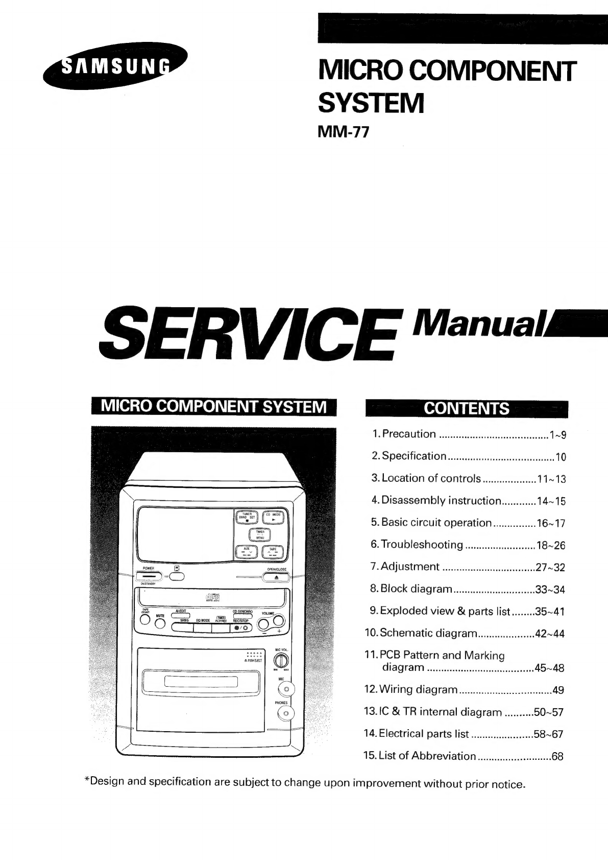
Samsung MM-77 User manual

MICRO
COMPONENT
SYSTEM
MM-77
S
ERVIC
Manual
i
MICRO
COMPONENT
SYSTEM
APF
CCAUT
ON
-csateistans
doce
Sale
dtaaaroeeeacsanrs
1~9
2;
SDOCITICATION
a:iinescetcctevecdav
unten
10
3.
Location
of
controls
........ccee
11~13
4.
Disassembly
instruction............
14~15
5.
Basic
circuit
operation...............
16~17
6.
TroubleSHOOTING
......ecceseeeeeeeees
18~26
FAQUUSUMIENT
siasrmiccihddiariereds
27~32
8.
Block
diagram........ccessseseseees
33~34
a
—
“SSE
vec
]
9.Exploded
view
&
parts
list........
35~41
10.Schematic
diagram...
42~44
11.PCB
Pattern
and
Marking
HAGMAN
asia
ste
senetuetrsannslncensadagenas
45~48
12.
Wiring
diagram
.....cccccccseseeeeeeeeens
49
13.IC
&
TR
internal
diagram
..........
50~57
14.
Electrical
parts
list...
eee
58~67
15.
List
of
Abbreviation
..........cccceeeees
68
*Design
and
specification
are
subject
to
change
upon
improvement
without
prior notice.

1.
Safety
precaution
1-1.
Class
1
laser
product
This
laser
disc
player
is
classified
as
a
CLASS
1
laser
product.
1-2.
Laser
warning
label
The
label
shown
below
may
be
affixed
or
not
according
to
country.
(UL)
(CSA)
(EU)
This
Product
Complies
with
CERTIFIED
ONLY
TO
CANADIAN
DHHS
Rules
21CFR,
Sub
ELECTRICAL
CODE.
chapter
J.At
date
of
Manu-
CLASS
1
facture
CERTIFIE
EN
VERTU
DU
CODE
LASER
PRODUCT
CANADIAN
DE
LELETRICITE
SEULEMENT
L
Location:
Enclosure
back.
(SCAN)
CAUTION
!
invisi8Le
LASER
RADIATION
WHEN
OPEN
AND
INTERLOCKS
DEFEATEO
AVOIDEXPOSURE
TO
BEAM
(EU)
ADVARSEL
USYNLIG
LASERSTRALING
VED
ABNING
NAR
SIKKERHEDSAFBRYDERE
ER
UDE
AF
FUNKTION
UL
:
Manufactured
for
U.S.A.
Market.
CSA
__
:
Manufactured
for
Canadian
Market.
UNDGAUDSAETIELSE
FOR
STRAUNG
EU
:
Manufactured
for
European
Market.
VARO:AVATTAESSA
JA
SUOJALUKITUS
OHITETTAESSA
;
‘
OLET
ALTTINA
NAKYMATTOMALLE
LASERSATEILYLLE
ALA
SCAN
:
Manufactured
for
Scandinavian
KATSO
SATEESEEN!
Market
arket.
VARNING\OSYNUG
LASERSTRALNING
NAR
DENNA
DEL
AR
OPPNAD
OCH
SPARREN
AR
URKOPPLAD
BETRAKTA
EJSTRALENI
Location
:
on
the
disc
clamper
or
inner
side
of
UNIT
door
or
nearby
UNIT
chassis.
1-3.Laser
beam
warning
1-4.
1-5.
ADVERSEL
-Usynlig
saserstraling
ved
abning,
nar
Sikkerhedsafbrydere
er
ude
af
funktion.
Undga
udsaettelse
for
straling.
VARNING
-Osylig
laserstralning
nar
denna
del
ar
Gppnad
och
sparr
ar
urkopplad.
Stralen
ar
farlig.
VARITUS
-Laite
sisaltaa
laserdiodin,
joka
lahettaa
nakymatonta
silmille
vaarallista
lasersateilya.
CAUTION
-Invisible
laser
radiation
when
door
is
open
and
interlocks
defeate.
Avoid
exposure
to
beam.
Laser
diode
specification
(Optical
pick-up)
¢
Material
:
GaAs+GaAlAs
*
Wavelength
:
760-800nm
*
Emission
duration
:
Continuous
*
Laser
Output
:
0.2mW
*
This
output
is
the
value
measured
at
distance
1.6mm
from
the
objective
lens
surface
on
the
optical
pick-
up
block.
*
Classification
:
CLASS
1
Warning
for
servicing
WARNING:
When
servicing,
do
not
approach
the
LASER
exit
with
the
eye
too
closely.
In
case
it
is
necessary
to
confirm
LASER
beam
emission,
be
sure
to
observe
from
a
distance
of
more
than
30cm
from
the
surface
of
the
objective
lens
on
the
optical
pick-up
block.
VARNING:
Nar
underhailningsarbeten
utfors,
narma
dig
forsiktigt
och
se
inte
pa
laserutstralningen
pa
for
nare
hall.
If
all
det
ar
n6dvandigt
att
betrygga
laserstralens
utstromning.
Var
saker
att
kontrollera
detta
fran
ett
avstaand
av
mer
an
30cm
(11.81
inch.)
fraan
den
objektiva
linsens
yta
pa
den
optiska
utsandningspunkten.
ADVARSEL:
Nar
repareringsarbejdet
udfoeres,
naerm
dig
forsigtigt
og
se
ikke
pa
laserudstralingen
paa
for
naer
haand.
“t
ilfaeldet
at
det
er
noedvaendigt
at
bestemme
laserstralens
udstraling.
Vaer
sikker
pa
kontrollere
dette
fra
en
afstand
af
mere
end
30cm
(11.81
inch.)
fra
den
objektive
linses
overflade
pa
den
optiske
udsendningspunkt.
VAROITUS:
Silmia
on
varottava
viemasta
liian
labeile
laser-poistokanavaa
huoiion
aikana.
Jos
on
valttamatonta
varmistaa
Laser-Sateen
paasto,
pysyttels
sita
tarkasteltaessa
vahintaan
30cm
etaiyydella
optisen
lukon
objecktiivilinssin
pinnasta..
MM-77
—1—

1-1-6.
(2
—
(3)
MM-77
Before
returning
an
instrument
to
the
customer,
always
make
a
safety
check
of
the
entire
instrument,
including,
but
not
limited
to,
the
following
items:
Be
sure
that
no
built-in
protective
devices
are
defective
or
have
been
defeated
during
servicing.
(1)
Protective
shields
are
provided
to
protect
both
the
technician
and
the
customer.
Correctly
replace
all
missing
protective
shields,
including
any
remove
for
servicing
convenience.
(2)
When
reinstalling
the
chassis
and/or
other
assembly
in
the
cabinet,
be
sure
to
put
back
in
place
all
protective
devices,
including,
but
not
limited
to,
nonmetallic
control
knobs,
insulating
fishpapers,
adjustment
and
compartment
covers/shields,
and
isolation
resistor/
capacitor
networks.
Do
not
operate
this
instrument
or
permit
it
to
be
operated
without
all
protective
devices
correctly
installed
and
functioning.
Be
sure
that
there
are
no
cabinet
openings
throught
which
adults
or
children
might
be
able
to
insert
their
fingers
and
contact
a
hazardous
voltage.
Such
openings
include,
but
are
not
limited
to,
excessively
wide
cabinet
ventilation
slots,
and
an
improperly
fitted
and/or
incorrectly
secured
cabinet
back
cover.
Leakage
Current
Hot
Check-With
the
instrume-nt
completely
reassembled,
plug
the
AC
line
cord
directly
into
a
120V
AC
outlet.
(Do
not
use
a
isolation
transformer
during
this
test.)
Use
a
leakage
current
tester
or
a
metering
system
that
complies
with
American
National
Standards
institute
(ANSI)
C101.1
Leakage
Current
for
App-
liances
and
Underwriters
Laboratories
(UL)
1270
(40.7).
With
the
instrument's
AC
switch
first
in
the
ON
positin
and
then
in
the
OFF
position,
measure
from
a
known
earth
ground
(metal
waterpipe,
conduit,
etc.)
to
all
exposed
metal
parts
of
the
instrument
(antennas,
handle
brackets,
metal
cabinets,
screwheads,
metallic
overlays,
control
shafts,
etc.),
especially
any
exposed
metal
parts
that
offer
an
electrical
return
path
to
the
chassis.
Any
current
measured
must
not
exceed
0.5
millamp.
Reverse
the
instrument
power
cord
plug
in
the
outlet
and
repeat
the
test.
See
Figure
1.
Any
measurements
not
within
the
limits
specified
herein
indicate
a
potential
shock
hazard
that
must
be
ellminated
before
returning
the
instrument
to
the
customer.
(Reading
should
not
be
above
0.5mA)
Leakahe
Currant
Tester
Test
all
exposed
metal
surfaces
2-Wire
Cord
Also
test
with
plug
reversed
(using
AC
adapter
plug
as
required)
FIG.
1
AC
Leakage
Test
(4)
Insulation
Resistance
Test
Cold
Check-(1)
Unplug
the
power
supply
cord
and
connect
a
jumper
wire
between
the
two
prongs
of
the
plug.
(2)
Turn
on
the
power
switch
of
the
instrument.
(3)
Measure
the
resistance
with
an
ohmmeter
between
the
jumpered
AC
plug
and
all
exposed
metallic
cabinet
parts
on
the
instrument,
such
as
screwheads,
antenna,
control
shafts,
handie
brackets,
etc.
When
an
exposed
metallic
part
has
a
return
path
to
the
chassis,
the
reading
should
be
between
1
and
5.2
megohm.
When
there
is
no
return
path
to
the
chassis,
the
reading
must
be
infinite.
If
the
reading
is
not
within
the
limits
specified,
there
is
the
possibility
of
a
shock
hazard,
and
the
instrument
must
be
repared
and
rechecked
before
it
is
returned
to
the
customer.
See
Figure
2.

Antenna
Terminal
Exposed
Melal
Part
Ohmmeter
1-1-7.
1-1-8.
1-1-9.
FIG.
2
Insulation
Resistance
Test
Read
and
comply
with
all
caution
and
safety-
related
notes
non
or
inside
the
cabinet,
or
on
the
chassis.
Design
Afteration
Warning-Do
not
alter
or
add
to
the
mechanical
or
electrical
design
of
this
instrument.
Design
alterations
and
additions,
including
but
not
limited
to,
circuit
modifications
and
the
addition
of
items
such
as
auxiliary
audio
output
connections,
might
alter
the
safety
characteristics
of
this
instrument
and
create
a
hazard
to
the
user.
Any
design
alterations
or
additions
will
make
you,
the
servicer,
responsible
for
personal
injury
or
property
damage
resulting
therefrom.
Observe
original
lead
dress.
Take
extra
care
to
assure
correct
lead
dress
in
the
following
areas:
(1)
near
sharp
edges,
(2)
near
thermally
hot
parts
(be
sure
that
leads
and
components
do
not
touch
thermally
hot
parts),
(3)
the
AC
supply,
(4)
high
voltage,
and
(5)
antenna
wiring.
Always
inspect
in
all
areas
for
pinched,
out-of-place,
or
frayed
wiring.
Do
not
change
spacing
between
a
component
and
the
printed-circuit
board.
Check
the
AC
power
cord
for
damage.
MM-77
1-1-10.
Components,
parts,
and/or
wiring
that
appear
to
have
overheated
or
that
are
otherwise
damaged
should
be
replaced
with
components,
parts
and/or
wiring
that
meet
original
specifications.
Additionally,
determine
the
cause
of
overheating
and/or
damage
and,
if
necessary,
take
corrective
action
to
remove
any
potential
safety
hazard.
Product
Safety
Notice-Some
electrical
and
mechanical
parts
have
special
safety-related
characteristics
which
are
often
not
evident
from
visual
inspection,
nor
can
the
protection
they
give
necessarily
be
obtained
by
replacing
them
with
components
rated
for
higher
voltage,
wattage,
etc.
Parts
that
have
special
safety
characteristics
are
identified
by
shading,
an
(x)
or
a
(
A\,)
on
sc-
hematisc
and
parts
lists.
Use
of
a
substitute
replacement
that
does
not
have
the
same
safety
characteristics
as
the
recommended
replacement
part
might
created
shock,
fire
and/or
other
hazards.
Product
safety
is
under
review
continuously
and
new
instructions
are
issued
whenever
appropriate.

2.
Servicing
notes
2-1.
Before
servicing
the
unit
Be
sure
to
observe
the
safety
notes
attached
on
label,
chassis,
cabinet
top,
cabinet
bottom
and
printed
circuit
board.
2-1-1.
Caution
on
laser
beammalfunction
Do
not
try
to
access
objective
lens,
when
DISC
is
not
on
the
tray.
When
pick-up
mechanism
replacement
is
required,
be
sure
to
turn
power
off.
2-1-2.
When
handling
parts
Tube,
tape
or
insulating
parts
are
used
for
sepa-ration
or
insulation
purposes.
Especially
parts
which
generate
excessive
heat
are
kept
away
from
PCB
or
any
other
sensitive
parts.
Therefore,
when
replacing
parts,
be
sure
to
replace
them
in
their
original
position.
2-1-3.
When
fixing
wires
Wires
should
be
fixed
in
such
a
way
with
cable-tie
so
they
won't
move.
When
finished
servicing,
be
sure
to
leave
unit
in
it's
original
configuration.
2-1-4.
Use
specified
parts
only
The
safety
specification
built
into
the
electronics
of
this
unit
require
that
you
use
specified
parts
only.
Do
not
use
any
other
replacements.
Using
other
parts
can
result
in
electrical
and
fire
hazard.
2-1-5.
After
servicing
is
complete
After
servicing
is
complete,
check
if
there
are
any
missing
parts
or
that
wires
are
properly
fixed
and
any
place
where
over
heating
or
shock
is
likely
to
occur,
can
be
found.
short
terminal
SOH91C1(CAR,
walkman)
SOH91VI(LDP)
MM-77
2-1-6.
Handling
the
optical
pick-up
*
The
laser
diode
in
the
optical
pick
up
may
suffer
electrostatic
breakdown
because
of
potential
static
electricity
from
clothing
and
your
body.
The
following
method
is
recommended.
(1)
Place
a
conductive
sheet
on
the
work
bench
(The
black
sheet
used
for
wrapping
repair
parts.)
(2)
Place
the
set
on
the
conductive
sheet
so
that
the
chassis
is
grounded
to
the
sheet.
(3)
Place
your
hands
on
the
conductive
sheet
(This
gives
them
the
same
ground
as
the
sheet).
(4)
Remove
the
optical
pick
up
block.
(5)
Perform
work
on
top
of
the
conductive
sheet.
Be
careful
not
to
let
your
clothes
or
any
other
static
sources
to
touch
the
unit.
*
Be
sure
to
put
on
a
wrist
strap
grounded
to
the
sheet.
*
Be
sure
to
lay
a
conductive
sheet
made
of
copper
etc.
which
is
grounded
to
the
table.
4
Mr
Pek
SSte5
vee
sy,
=
cp
Notes
vy
aay
*
OSES
IM
¢
1M
;
'
Pe
APS”
Lr
ea
a
SS
‘0
THE
UNIT
AA
|
a
\s
WS,
Ant
a
<
A
(1)
WRIST-STRAP
oe
CONDUCTIVE
SHEET
FOR
GROUNDING
1M
f
(6)
Short
the
short
terminal
on
the
PCB,
which
is
inside
the
Pick-Up
ASS'Y,
before
replacing
the
Pick-Up.
(The
short
terminal
is
shorted
when
the
Pick-Up
Ass'y
is
being
lifted
or
moved.)
(7)
After
replacing
the
Pick-up,
open
the
short
terminal
on
the
PCB.
ON
Sal
a
EF)
terminal
SOH-A1
(CMS-V10,CMS-V30)
terminal
SOH94T4N
(CMS-V10,CMS-V30)

2-2.
Servicing
Precautions
CAUTION:
Before
servicing
Instruments
covered
by
this
service
manual
and
its
supplements,
read
and
follow
the
Safety
Precautions
section
of
this
manual.
Note:
If
unforseen
circument
create
conflict
between
the
following
servicing
precautions
and
any
of
the
safety
precautions,
always
follow
the
safety
precautions.
Remember:
Safety
First.
2-2-1.
General
Servicing
Precautions
(1)
a.
Always
unplug
the
instrument's
AC
power
cord
from
the
AC
power
source
before
(1)
removing
or
reinstalling
any
component,
circuit
board,
module
or
any
other
instrument
assembly,
(2)
disconnecting
any
instrument
electrical
plug
or
other
electrical
connection,
(3)
connecting
a
test
substitute
in
parallel
with
an
electrolytic
capacitor
in
the
instrument.
b.
Do
not
defeat
any
plug/socket
B+
voltage
interlocks
with
which
instruments
covered
by
this
service
manual
might
be
equipped.
c.
Do
not
apply
AC
power
to
this
instrument
and/or
any
of
its
electrical
assemblies
unless
all
solid-state
device
heat
sinks
are
correctly
installed.
d.
Always
connect
a
test
instrument's
ground
lead
to
the
instrument
chassis
ground
before
connecting
the
test
instrument
positive
lead.
Always
remove
the
test
instrument
ground
lead
last.
Note:
Refer
to
the
Safety
Precautions
section
ground
lead
last.
(2)
The
service
precautions
are
indicated
or
printed
on
the
cabinet,
chassis
or
components.
When
servicing,
follow
the
printed
or
indicated
service
precautions
and
service
materials.
(3)
The
components
used
in
the
unit
have
a
specified
flame
resistance
and
dielectric
strength.
When
replacing
components,
use
components
which
have
the
same
ratings.
Components
identified
by
shading,
by
(x)
or
by
(.1
)
in
the
circuit
diagram
are
important
for
safety
or
for
the
characteristics
of
the
unit.
Always
replace
them
with
the
exact
replacement
components.
MM-77
(4)
An
insulation
tube
or
tape
is
sometimes
used
and
some
components
are
raised
above
the
printed
wiling
board
for
safety.
The
internal
wiring
is
sometimes
clamped
to
prevent
contact
with
heating
components.
Install
such
elements
as
they
were.
(5)
After
servicing,
always
check
that
the
removed
screws,
corponents,
and
wiring
have
been
installed
correctly
and
that
the
portion
around
the
serviced
part
has
not
been
damaged
and
so
on.
Further,
check
the
insulation
between
the
blades
of
the
attachment
plug
and
accessible
conductive
parts.
2-2-2.
Insulation
Checking
Procedure
Disconnect
the
attachment
plug
from
the
AC
outlet
and
turn
the
power
ON.
Connect
the
insulation
resistance
meter
(500V)
to
the
blades
of
the
attachment
plug.
The
insulation
resistance
between
each
blade
of
the
attachment
plug
and
accessible
conductive
parts
(see
note)
should
be
more
than
1
Megohm.
Note:
Accesible
conductive
parts
include
metal
panels,
input
terminals,
earphone
jacks,
etc.

2-3.
ESD,
Precautions
Electrostatically
SensitiveDevices
(ESD)
Some
semiconductor
(solid
state)
devices
can
be
damaged
easily
by
static
electricity.
Such
components
commonly
are
called
Electro-
statically
Sensitive
Devices
(ESD).
Examples
of
typical
ESD
devices
are
integrated
circuits
and
some
field-
effect
transistors
and
semiconductor
chip
com-
ponents.
The
following
techniques
should
be
used
to
help
reduce
the
incidence
of
component
damage
caused
by
static
electricity.
(1)
Immediately
before
handling
any
semiconductor
component
or
semiconductor-equipped
assembly,
drain
off
any
electrostatic
aharge
on
your
body
by
touching
a
known
earth
ground.
Alternatively,
obtain
and
wear
a
commercially
available
discharging
wrist
strap
device,
which
should
be
removed
for
potential
shock
reasons
prior
to
applying
power
to
the
unit
under
test.
(2)
After
removing
an
electrical
assembly
equipped
with
ESD
devices,
place
the
assembly
on
a
con-
ductive
surface
such
as
aluminum
foil,
to
prevent
electrostatic
charge
buildup
or
exposure
of
the
assembly.
(3)
Use
only
a
grounded-tip
soldering
iron
to
solder
or
unsolder
ESD
devices.
(4)
Use
only
an
anti-static
solder
removal
device.
Some
solder
removal
devices
not
classified
as
"anti-static"
can
generate
electrical
charges
sufficient
to
damage
ESD
devices.
(5
—
Do
not
use
freon-propelled
chemicals.
These
can
generate
electrical
charges
sufficient
to
damge
ESD
devices.
MM-77
(6)
Do
not
remove
a
replacement
ESD
device
from
its
protective
package
until
immediately
before
your
are
ready
to
install
it.
(Most
replacement
ESD
devices
are
packaged
with
leads
electrically
shorted
together
by
conductive
foam,
aluminum
foil
or
comparable
conductive
materials).
(7)
Immediately
before
removing
the
protective
materials
from
the
leads
of
a
replacement
ESD
device,
touch
the
protective
material
to
the
chassis
or
circuit
assembly
into
which
the
device
will
be
installed.
CAUTION:
Be
sure
no
power
is
applied
to
the
chassis
or
circuit,
and
observe
all
other
safety
precautions.
@
Minimize
bodily
motions
when
handling
unpack-
aged
replacement
ESD
devices.
(Otherwise
harmless
motion
such
as
the
brushing
together
of
your
clothes
fabric
or
the
lifting
of
your
foot
from
a
carpeted
floor
can
generate
static
electricity
sufficient
to
damage
an
ESD
device).

3.
Chip
replacement
3-1.
Precaution
for
the
Chip
Replacement
(1)Do
not
touch
the
part
body
directly
with
the
soldering
iron.
ICS,
especially
TSOP,
are
easily
damaged
by
heat.
(2)
Use
care
regarding
soldering
iron
tip
and
avoid
rapidly
heating
parts.
Some
parts
can
be
damaged
by
sudden
heating.
Preheat
the
part
at
about
100°C
for
several
minutes
before
installing
it.
(3)
Use
soldering
tip
temperature
of
about
240°C
or
larger
parts,
use
a
slightly
higher
temperature
(about
280°C).
(4)
The
thin
(0.3mm)
solder
for
miniature
parts
does
not
contain
adequate
flux.
Supplementary
flux
is
thus
needed
in
most
cases.
The
NoteMaster
486S/25N
series
systems
are
manufactured
using
flux
which
can
be
cleaned
by
water
in
the
factory.
When
your
replace
the
part
or
troubleshooting,
use
proper
flux
and
solder
which
can
be
cleaned
by
water.
Soldering
area
will
corrode,
if
proper
flux
and
solider
are
not
used
in
replace.
And
it
may
cause
a
fatal
error
to
the
system.
(5)
Use
care
not
to
damage
the
circuit
pattern,
especially
when
removing.
(6)
Because
of
the
many
pins,
cleanliness
of
the
pattern
is
extremely
important
after
removing
the
IC.
(7)
Use
care
to
avoid
solder
bridges.
Remove
any
that
occurs.
(8)
Position
the
part
carefully.
This
will
also
affect
the
soldering
operation.
Be
very
precise
in
positioning
the
IC.
Soldering
opposite
pins
first
holds
the
IC
in
place
and
makes
soldering
the
other
pins
easier.
(9)
Do
not
reuse
removed
parts.
(10)
Check
for
solder
joints,
especially
miniature
parts
with
small
lead.
(11)
A
defective
trimming
resistor
cannot
be
adjusted
externally.
Replace
with
an
ordinary
variable
resistor.
(12)
It
is
important
to
inspect
the
work
with
a
magnifier.
Check
after
installing
(cold
solder
joints,
etc).
3-2.
Tools
for
the
Chip
Replacement
The
tools
for
the
chip
replacement
are
as
follows:
(1)
Thin
tip
type
soldering
iron
(2)
Small
flat-blade
tip
type
soldering
iron
(3)
Special
desoldering
tip
iron
(4)
Airblower
unit
(5)
Flat
Package
Pick-up
MM-77
6)
Flux
can
be
cleaned
by
water
7)
0.3mm
thin
solder
can
be
cleaned
by
water
8)
Desoldering
wire
9)
Tweezers
3-3.
Chip
Resistors
and
Chip
Capacitors
3-3-1.
Kind
jof
the
Part
The
kind
of
chip
resistors
and
chip
capacitors
as
follows
(1)
Thick
Film
Chip
Resistors
(2)
Carbon
Film
Chip
Resistors
(3)
Metal
Film
Chip
Resistors
(4)
Chip
Ceramic
Capacitors
(5)
Chip
Trimming
Resistors
3-3-2.
Removing
the
Part
The
kind
of
chip
resistors
and
chip
capacitors
as
follows
(1)
Using
two
soldering
irons:
(D
Use
thin
tip
soldering
irons.
)
Use
soldering
tip
temperature
of
about
280°C
@)
Simultaneously
heat
both
ends
of
the
part.
@
While
heating,
grasp
the
part
with
the
tips
of
the
soldering
irons
and
remove
it.
©)
Use
desoldering
wire
to
completely
remove
the
old
solder
from
the
part
location
of
the
board.
©
A
clean
pattern
for
installing
the
new
part
is
very
important.
FIG,
4
3-3-3.
Installing
the
Part
(1)
Clean
the
area
where
the
new
part
is
to
be
mounted.
(2)
Apply
flux.
(3)
Set
part
correctly
into
position,
prevent
it
from
shifting.
(4)
Bring
the
soldering
iron
tip
close
to
the
part
contact
without
actually
touching
it.
Melt
thin
(0.3mm)
solder
between
the
tip
and
part
so
that
it
flows
into
the
part
contact.
(5)
Check
work
quality
with
a
magnifier.

3-4.
Chip
Tantalum
Capacitors
and
Chip
Filters
3-4-1.
Kind
of
the
Part
The
kind
of
chip
tantalum
capacitors
and
chip
filters
are
as
follows:
(1)
Chip
Inductors
(2)
Chip
Tantalum
Capacitors
(3)
Chip
Tantalum
Electrolytic
Capacitors
(4)
Chip
Aluminum
Electrolytic
Capacitors
(5)
Chip
Transformers
(6)
Chip
Filters
3-4-2.
Removing
the
Part
(1)
Using
special
desoldering
iron:
(D
Select
soldering
tip
according
to
part
size.
@
Bring
the
tip
into
contact
with
the
soldered
points.
When
the
solder
melts,
remove
the
part.
@Remove
the
old
solder
with
desoldering
wire.
(1)
Using
two
soldering
irons:
(D
Use
small
flat-blade
tips.
(Heat
both
ends
of
the
part
simultaneously.
@
When
the
solder
melts,
grasp
and
remove
the
part
with
the
soldering
iron
tips.
@
Remove
the
old
solder
with
desoldering
wire.
W..
\b=
Awe
wy
!
NE
Wwe
3-4-3.
Installing
the
Part
(1)
Clean
the
area
where
the
new
part
is
to
be
mounted.
(2)
Apply
flux
(3)
In
part
correctly
into
position,
prevent
it
from
shifting.
(4)
Use
sharp
soldering
iron
tip.
Bring
close
to
the
Part
contact
without
actually
touching
it.
Melt
thin
solder
between
the
tip
and
part
so
that
if
flows
into
the
part
contact.
(5)
Check
work
quality
with
a
magnifier.
FIG.
5
MM-77
3-5.
Chip
VRs,
Chip
Trimmer
Capacitors,
Diodes
and
Tr.
3-5-1.
Kind
of
the
Part
The
kind
of
the
part
is
as
follows:
(1)
Chip
VRs
(2)
Chip
Trimmer
Capacitors
(3)
Diode
(4)
Transistors
3-5-2.
Removing
the
Part
(1)
Using
two
soldering
irons:
@
Use
small
flat-blade
tips.
@
Heat
the
leads
of
the
part
simultaneously.
@)
When
the
solder
melts,
grasp
and
remove
the
part
with
the
soldering
iron
tips.
@
Remove
the
old
solder
with
desoldering
wire.
3-5-3.
Installing
the
Part
Oy
YS
/
Y
FIG.
6
(1)
Clean
the
area
where
the
new
part
is
to
be
mounted.
(2)
Apply
flux
(3)
Set
part
correctly
into
position,
prevent
it
from
shifting.
(4)
Use
sharp
soldering
iron
tip.
Bring
close
to
the
part
contact
without
actually
touching
it.
Melt
thin
solder
between
the
tip
and
part
so
that
it
flows
into
the
part
contact.
3-6.
Chip
ICs
3-6-1.
The
kind
of
the
Chip
ICs
The
kind
of
the
chip
ICs
are
as
follows:
(1)
SOP
(Small
Outline
Package)
IC
(2)
SSOP
(Shrink
Small
Outline
Package)
IC
(3)
VSOP
(Very
Small
Outline
Package)
IC
(4)
QFP
(Quad
Fiat
Package)
IC
(5)
VOFP
(Very
Quad
Flat
Package)
IC
(6)
PLCC
(Plastic
Leaded
Chip
Carrier)
IC
(7)
TSOP
(Thin
Small
Outline
Package)
IC

3-6-2.
Removing
the
Part
(1)
Using
special
desoldering
iron:
Select
the
tip
according
to
the
size
and
shape
of
the
IC.
@
Thin"
the
tip
with
a
small
amount
of
the
IC
leads.
@)
Set
the
tip
squarely
over
the
IC
leads.
@
When
the
solder
melts,
carefully
twist
the
iron.
©)
Raise
and
remove
the
IC.
(2)
Using
shaped
airblower
unit:
@
Select
the
correct
nozzle.
@)
Select
the
temperature
and
airblow
(suggested:
temperature:
7,
airblow:
4)
@)
Engage
the
IC
removing
tool.
@
Use
the
airblow
to
preheat
the
IC
for
about
5
seconds,
then
heat
with
the
nozzle
until
the
IC
remover
lifts
the
part
from
the
board.
=
ea
|
FIG.
7
MM-77
3-6-3.
Installing
the
Part
(1)
Use
desoldering
wire
to
remove
the
previous
older.
(2)
Clean
the
location.
(3)
Apply
flux.
(4)
Position
the
IC
and
solder
two
pins
at
opposite
sides.
(5)
Use
a
sharp
tipped
soldering
iron
and
carefully
solder
each
pin.
(After
graining
experience,
a
thicke
tip
can
be
used
for
better
work
efficiency.)
(6)
Remove
any
solder
bridges
with
desoldering
wire.
(7)
Inspect
the
work
with
a
magnifier.

2.
Specification
2-1.
General
section
2-1-4
POWER
SOUNCE
vs
cazecsic.aes
cen
cusglceastvusdeidvuds
sacs
ie
sacedansvactaevea
dacuuadovts
siaveeas¥Raasacertebneodlunelecectsacdss
See
Label
Rating
2
AZ
A
POWEE
CONMSUNTIDUIGM
ces
vst
cattewssesasatencca
dav
penceacse
ipa
taeewtouetiorieensctutadhesddsiesen
ins
oetseieit
octasie
tet
ret
ath
eek
14-2
85
W
2='|23s-DIVONSION
5
.cevvs
cs
eczevessle2sdccsacesvhvsdacacacd
santas
cdfnctavtaas
toni
d
Snevivusteavieidesdaoedeenunines
500 (W)
x
255(H)
x
215(D)
mm
2-2.
Amp
section
222711,
POWOP
OUT
PUE.
3429505
csces
Feasedssataudi
tv
cves
vvsedsedaevastevs
cobaun
cote:
ieedhe
Seo
adeba
tne
cde
aceeme
van
ceesftonn
he
13
W/CH
(6Q){10%
DT)
22272
SPREQUENCY
TESPONSC
x.
s25sofazvaresesesa
sacs
ak
cits
idvssecuutedaevde
occupa
vaessucesiudveaddtevian
diaslsds
GOSS
Lc
cscseicckke
20
Hz~20
KHz
Paor
ot
SIG!
LO
MIOISE
EAU
5504.
serch
wes
doves
dis
asiedodetdcm
dise
toad
toed
cutesa
de
dheasians
cacensast
dan
Dakewt
Reese
castete
dee
te
ge
80
dB
22-4
Channel
Se
Dalat!
OF
etivectospuns
ee
cause
ch
asad
accomsnantam
deta
cadet
htt
cen
caesiy
ees
ss
cla
tee
65
dB
2-2-5.
(MPUL:
SONSILIVILY
<2,
.1c2-s:css
3
sends
nedetdadevatigivessbccacszedeeses
obiees
cavsiveiedyocoasusa
tank
udeelsteacdaceadeove
dee
cede
AUX
250
mV
MIC
2.5
mV
2-3.
Tuner
section
2-3-1.
FM
part
(TSF
FOEQUENTY
FANG
Oia:
.iicieteclecsScceiageiavinitd
tskceoncvode
ses
yusathvaluec
teins
oediteinised
cdsduacieantlocwiavi
atta
Pade
87.5~108
MHz
74
Fa
EoFe
[SSE
1
ero)
10
4
ann
ee
rT
se
Pry
SOB
7
OR
15
dB
(3)
SIO
Nal
LO
NOISES
RATIO
ante
selene
ts
cat
tesece
Aeadusigtash
co
chuctoass
erat
agiat
tink
eat
ayuil
glen
ruaei
Gate
tiat
a
eaeteaghencsleettetche
eins
waesee
55
dB
(AD
AFG
HERO
NCE
ARO
5
oc
shart
wtenteasnetosbevenvastia
Sees
ioaniceateededaaiate:
ck
Gaede
means
conteecea
hands
teece
doa
ee
easy
Rice
SS
40
dB
19)
LOAD
MAINO
IG
CISEON
CO
sin.
ses
ent
canrctsivass
ctarat
swung
tacwstetaeudautonatat
eteaOearsere.
tase
Mocs
alone
tacit
ax
ehcatcnh
atdatinneatecocdedae
0.5
%
WG
SEGIEO
SOD
ALE
OPN
acts
cp
estsiiencta
Nc
82
ba
laa
eck
ead
et
on
SS
DS
oC
ca
Te
ea
cht,
nk
aplace
rhe
35
dB
2-3-2.
AM
(MW)
Part
CU)
ERO
Ue
CY.
Fel
sas
Castaic
ty
Reus
isaaisasteaiieed
atts
av
cp
sean
cts
dtaed
ents
arcvtgenbeann
milan
hah
wa
anndutonnabuestodeane
sekaback
522~1611
KHz
AZ
PWS
ATG
SO
ri
STE
IBY
cases
as
exe
iis
c2t
eel
cautarsuss
deseessr
ute
Oe
lian
Heseosnee
tebe:
dane
sat
yaaa
dete
a
tedtadgieinia
tated
dae
axel
ea
tce eee
54
dB
CS
OCT
PTG|
LO
MOISE
TAU
Gast
case
Goran
ciestacie\
sos
budts
aad
desu
usteaternclcadaablewheeaeniceasteete
cupihas
Scrat
duran
ht
suat
ctpstivan
ate
seusnsleecs
40
dB
VA
TINTEPIGTERICE:
PALO
ipssucacts
(cates
Vaxoast
Ce
enansies
tt
stn
tonlac
huis
sit
Gr
cide
Ose
te
has
ac
hata
lua
tice
a
abe.
ke
eta
at
ee
33
dB
(5),
Gta!
Marinoni
Ci
StONiOM
nestle
ad
tae
eal
eve
ate
alee
Maal
ile
auth
ke
eg
Wea
tae
dea
ta
eat
cae
ate”
2%
2-3-3.
LW
(option)
part
CUP
PRECenGy
aig
Gistass
cscicepaavtatets
ner
Sevsc
apes hata
ide
on
Vonautad
dwiathaganalauanvounneamnad
tala
aad
Aaliadesaege
146
~
290
KHz
(ZEISAD
Se
SOMSIEINILY
ansincesndvecitiasa
tas
dscseeschucueade
sais
cugepauscnss
sbobens
atlisntaladoadsSenuoaulateadsoasausstcvhe
adunvvcnicdwaesa
vars
inacedbnaahes
60
dB
USPOOUIN
WALIO
atecesc
tule
ouctapecd
ston
ch
ots
Covi
lvadu
rel
aa
ltt
alenee
tetas
la
hie
Oh
ile
Mee
tesa
alt
alcatel
thd
Sac
eee
even
33
dB
2-4.
Deck
section
SrA
ORG
ING
VPA
LS
cots
shules
su
eta
bsicdy
leony
lucas
ed
ote SiS
saa
cad
aminedod
eae
dada
acttetanacthicdatanaseuestanluudesatarieeas
125
Hz~8
KHz
BEL
NNO
ELUTE
Pectin
ciated
oxteaseatacet
eas
es
iat
ve
tuners
dee
edacauatynca
inka
Sve
dansatled
cater
ntedstatlaecaca
wei,
ekatels
0.2%
ZoAP
Ss
PTASIDIOOHGCE
janis
sib
nlaks
aesebtaiene
eiiibdalalintereieiot
anantnacdet
snctius.opatelaead
usta
alte
SW
Mea
ac
Ban
tes
60
dB
2-4-4.
Signal
to
noise
ratio
(Record/Play
Mod
e).........ssssssssssssescscssscsesesvsssvstssecscseasacasececsescsusasacavssavecscasaueseaees
40
dB
ZrO
OAR
Ee
POU
Cl
EAS
gsi
on
oats
ace
ace
ai
ta
alah
Se
Re
Ra
oh
a
a
aa
ite
ache
RE
About
120
second
2-5.
CD
section
Pa
al
C19
1001
gL
a
191
(Re
Ae
eee
ey
Cen
20
Hz~20
KHz
(+
1.5
dB)
2-25
CHAMME!
SE
PALA
ORM
case
rcedvacaszac
aka!
nislendaceh
tag
Shouse
elun
lueaeanauban
teatbestasuediec
tas
aa
eielied
asia
Or
aseseteeeoneds
85
dB
(1
KHz)
2-9-3)
Otel:
Hea
rOiGMi
CIStOLEOM
a
siteids
25
As
occas
atten
cea
tuaua
eaemate
th
ie
carta
ss
jase
Sou
rad
caeusttads
poo
balk
s@bia
0.05
%
ZB
o
SIQUAIO
TIOISE
FAN
Ones
i
tender
MtoN
Siecs
aaa
taal
hee
Yul
an
aaa
duceetutce
eden
aat
Madea
ecst
95
dB
(1
KHz
0
dB)
2-08
DA
CONVEISION
x
cceeascartente
torent
eM
Vleet
Alea
tacit’
tne
fale
Rio
Se
le
ee
Amt
May
Pues
8
over
MM-77
—
10
—

3.
Location
of
controls
3-1.
Front
view
DISPLAY
FUNCTIONS
MENU
POWER
ON/OFF
CD
COMPARTMENT
CASSETTE
LENGTH
OPEN/CLOSE
SELECTION
FOR
COMPACT
DISC
COMPARTME
COMPACT
DISC
SYNCHRONISED
RECORD
CD
RECORD
COUNTER
RESET
(CASSETTE
ONLY)
SOUND
CUT-OFF
BASS
AMPLIFICATION
VOLUME
RECORD/STOP
(CASSETTE
ONLY)
TIMER
SWITCH
ON
AND
OFF
EQUALIZER
MODES
MICROPHONE
VOLUME
ADJUSTMENT
MICROPHONE
CONNECTOR
HEADPHONES
CONNECTOR
CASSETTE
PLAYER
MM-77
—11—

3-2.
Rear
view
AM
AERIAL
CONNECTOR
TERMINALS
FM
AERIAL
CONNECTOR
TERMINALS
(OPTION)
AM
AERIAL
CONNECTOR
TERMINALS
REAT
CUT
ANTI-PARASITE
SWITCH
(OPTION)
AUXILIARY
SOURCE
CONNECTORS
FM
AERIAL
CONNECTOR
TERMINALS
LOUDSPEAKER
CONNECTOR
TERMINALS
VOLTAGE
SELECTOR
(OPTION)
|
i
eee
|
|
|
eR
=.
L_VOLTAGE
SeL_|
MAINS
LEAD
CONNECTION
SOCKET
MM-77
—
12
—

3-3.
Remote
control
INFRA=RED
SIGNAL
TRANSMITTER
POWER
ON/OFF
TRACK
SELECTION
AND
FORWARD
SEARCH
TRACK
SELECTION
AND
REVERSE
SEARCH
TWO-FIGURE
TRACK
SELECTION
TRACK
INTRODUCTION
SCAN
PRESET
RADIO
STATION
SELECTION
RADIO
STATION
STORAGE
TRACK
PROGRAMMING
STOP
AND
CANCEL
PLAY
AND
PAUSE
RANDOM
PLAYBACK
TRACK
REPEAT
RADIO
RECEPTION
SELECTION
FREQUENCY
BAND
SELECTION
CHECK-TIMER-ON/OFF
SLEEP
CLOCK
AUTOMATIC
SWITCH
OFF
TIMER
CHECK CLOCK
SETTING
TIMER
SWITCH
ON
AND
OFF
SOUND
OUT-OFF
FUNCTION
SELECTION
VOLUME
INCREASE
FREQUENCY
AND
STATION
SELECTON
AND
TIME
SETTING
VOLUME
DECREASE
PLAYBACK
MODE
SELECTION
(AUTO-REVERSE)
REVERSE
MODE
COUNTER
RESET
REVERSE
PLAY
(SIDE
B)
PAUSE/RECORD
R
T
?
FORWARD
PLAY
(SIDE
A)
STOP
(PLAYBACK/RECORD)
FAST
FORWARD/FORWARD
SEARC
REWIND/REVERSE
SEARCH
MM-77
—
13
—

4.
Disassembly
instruction
Remove
the
plug
from
the
well
outlet
before
disassembling
the
unit
4-1.
How
to
disassemble
the
rear
of
4-3.
How
to
disassemble
CD-Mecha
cabinet.
(Fig.
1)
(Fig.
3)
4-1-1.
Remove
nine
screws
of
@)
and
eight
of
@
ofitsrear
part.
4-3-1.
Pullits
tray
foreward
and
then
raise
its
cover
tray
of
@)
upward
to
pull
it
out.
4-1-2.
Pull
its
rear
part
out
backward
horizontally
as
shown
in
the
Fig.
1.
4-3-2.
Remove
one
screw
of
3)
another
one
screw
of
@)
and
then
pull
CD-Mecha
of
@
out.
4-2.
How
to
disassemble
tuner
PCB
4-4.
How
to
disassemble
Main
PCB
and
Holder
back.
(Fig.
2)
(Fig.
4)
4-2-1.
Remove
one
screw
of
@
and
then
trun
Tuner
PCB
of
@
down
aside
a
little
to
pull
it
out
backward.
4-1-2.
Remove
one
screw
of
@)
and
then
raise
Holder
back
@
upward
to
pull
it
out
backward.
4-4-7,
Pull
Main
PCB
of
(2)
backward
horizontally
to
pull
it
out.
es
MM-77
-14.

4-5.
How
to
disassemble
the
front
of
cabinet.
(Fig.
5)
4-5-1.
Remove
three
screws
of
@
and
then
pull
Cabinet
bottom
of
@)
out
backward.
MM-77
-
15
-

5.
Basic
circuit
operation
5-1.
u-com
No.
PORT
Name
1/0
Function
=o
1
P5
2
BGNS_RST
oO
BGNS
RESET
2
PWM1
VOL_ST
oO
VOLUME
IC
STROBE
3
P2
0
OPEN
S/W
I
CD
DOOR
OPEN
S/W
4
1
CLOSE
S/w
|
CD
DOOR
CLOSE
S/W
5
2
OPEN
MT
oO
CD
DOOR
OPEN
MOTOR
6 3
CLS
MOT
@)
CD
DOOR
CLOSE
MOTOR
7
4
SENSE
|
CD
SENSE
8
5
MUTE
oO
CD/TUNER/TAPE
MUTE
9 6
XLT
O
CD
XLT
10
7
LD_XRST
oO
CD
LD/XRST
CONTROL
11
TEST
12
RES
RESET
13
XT
1
14
XT
2
15
vss
GND
16
CF
1
8MHz
17
CF
2
8MHz
18
VDD
19
P8
0
KEY
1
|
A/D
KEY
INPUT1
20
1
KEY
2
I
A/D
KEY
INPUT2
21
2
EQ
R
|
EQ
LEVEL
INPUT
(RIGHT)
22
3
EQ
L
|
EQ
LEVEL
INPUT
(LEFT)
23
4
AMPS
IN
|
TAPE
AMPS
SIGNAL
IN
24
5
TUN_OPT
|
TUNER
A/D
OPTION
25
6
HALL
I
TAPE
HALL
SIGNAL
IN
26
7
GFS
I
CD
GFS
27
P7
0
SCOR
|
CD
SCOR
INTERRUPT
28
1
INH
|
POWER
CORD
CHECK
29
2
FOK
|
CD
FOCUS
OK
30
3
REMOCON
I
REMOCON
PULSE
IN
31
S
1
GRID
1
32
2
2
33
3 3
34
4
4
35
5 5
36
6
6
37
7
7
38
8
8
39
9 9
40
10
10
41
11 11
42
12 12
43
13
13
44
14
14
45
15
15
46
16
47
VDP
48
vP
49
64
SEG
1
50
S
2
SEG
2
MM-77
—16—

No.
PORT
Name
1/0
Function
51
SEG
14
SEG
3
|
52
13
4
53
12
5
54
11
6
55
10
7
56
9
8
57
8
9
58
10 10
59
11 11
60
12
12
61
13 13
62
14 14
63
15
15
64
16
16.
65
PO
0
Q3(C)
66
1
Q2(B)
67
2
Q1(A)
68
3
Q4(DATA)
69
4
G1
(SEL1)
70
5
G2
(SEL2)
EXPAND
IC
CONTROL
71
6
PWR_SNS
oO
POWER
SENSE
72
7
BGNS_CH
O
BGNS
CHANNEL
SELECT
73
P1
0
BGS_CLK
oO
BGS
CLOCK
74
1
SUBQ
|
SUBQ
75
2
CLKSOCK
O
CLOCK/SOCK
76
3
DATA
oO
CD
SUBQ
DATA
77
4
STEREO
I
STEREO
CHECK
78
5
SD
|
79
6
MO/ST
O
MONO/STEREO
80
7
STOUT
|
81
P3
0
TUN_DAT
oO
TUNER
DATA
82
1
TUN_CLK
Oo
TUNER
CLOCK
83
2
TUN_CE
oO
TUNER
CE
84
3
STRO
oO
85
4
REC
oO
TAPE
RECORD
86
5
MOTOR
(@)
TAPE
MOTOR
87
6
SOL
O
TAPE
SOLENOID
ON/OFF
88
7
PLAY
oO
TAPE
PLAY
89
vss
90
VDD
91
P4
0
REC_MUT
Oo
TAPE
RECORD
MUTE
92
1
BGNS_MUT
O
-BGNS
MUTE
ON/OFF
93
2
BGNS_NAR
|
BGNS
NAR
94
3
R_REC
|
R
REC
PROTECT
(L)
95
4
MODE
!
DECK
MECHA
,ModeiL)
96
5
HALF
|
TAPE
existence
or
nonexistence
(L)
97
6
F_REC
|
F
REC
PROTECT
(L)
98
7
CD_HIGH
Oo
CD
HIGH
SPEED
(H)
99
P5
0
BGNS_ST
oO
BGNS
STROBE
100
1
BGNS_DAT
Oo
BGNS
DATA
MM-77
47

5-2.
CD
section
1)
RF
Amp(KA9220)
:
NIC9220
RF
1-V
Amp(1)
and
RF
I-V
Amp
(2)
are
converted
to
voltage
via
58K
internal
resistance
of
58kQ
from
the
current
of
PD1(A+C)
and
PD2
RI
Baal
(B+D)
;
then,
this
voltage
is
added
to
RF
summing
amplifier.
RFO
The
signal
(A+B+C+D)
is
applied
to
RFO
(No.2
terminal).
RF
output
voltage can
be
calculated
as
follows:
RF
1-V
AMP(1)
58K
Ba
ae
@
|
VRF
=
-R3
x
(iPD1
+
iPD2)
+
RF
1-V
AMP(2)
RF
=-R3
x
(V1/R1
+
V2/R2)
=-R3
x
(V1/10K
+
V2/10K)
=-R3/10K
x
(V1
+
V2)
2)
FOCUS
ERROR
Amp(KA9220)
:
NIC9220
FOCUS
ERROR
Amp
is
the
circuit
which
amplifies
the
difference
between
RF
I-V
Amp(1)
output(A+C)
and
RF
I-V
R2
Amp(2)
output
(B+D).
74k
These
two
signals
are
supplied
to
(-)
and
(+)
input
terminals
C1
25P
of
FOCUS
ERROR
Amp.
The
FOCUS
ERROR
signal
RI
||
}
———+
=
resulting
from
this
difference
voltage
is
applied
to
FE
-(B+D
MUS
(Terminal
No.
57).
The
FE
output
voltage
of
this
low
(B+D)
He
a
67)
frequency
component
varies
depending
on
{
(A+C)
-
(B+D)
}.
a
eae
VFE
can
be
obtained
as
follows.
32K
c2
asp
|
rea
we
VFE
=
(R2/R1)
x
(V2-V1)
=
5.4(V2-V1)
FE
Bias
This
FOCUS
ERROR
voltage
is
sent
to
FOCUS
SERVO
circuit
to
maintain
optimum
focusing.
Vcc
oe
GND
3)
FOCUS
SERVO
SYSTEM(KA9220)
:
NIC9220
The
diagram
of
Focus
Servo
System
is
shown
in
the
following.
When
FS3
is
ON,
high
frequency
gain
decreases
in
the
form
of
low
frequency
time
constant
by
pin
17,
pin
19,
and
capacitor
connected
to
internal
resistance.
The
capacitor
between
pin18
and
GND
has
the
time
constant
picking
up
the
low
frequency
operated
in
PLAY
mode.
PHASE
COMPENSATION
The
maximum
frequency
of
focus
phase
compensation
is
inversely
proportional
to
the
resistance
connected
to
pin7.
Focus
search
peak
is
about
1.1
Vp-p,
and
is
inversely
proportional
to
the
resistance
connected
to
pin22,23
;
however,
if
this
resistance
changes,
the
peak
of
track
jump
and
sled
kick
changes.
The
inversion
input
of
FZC
comparator
is
set
to
5.7%
of
the
difference
between
Vcc
and
VC(pin69)
{
5.7%
x
(Vcc
-VC)
}.
Note:
If
the
resistance
connected
to
pin
7
changes,
the
phase
compensation
peak
of
focus,
tracking,
sled
servo
changes.
At
the
same
time,
‘op-amp’
dynamic
range
and
offset
voltage
also
change.
MM-77
—
18
~

4)
TRACKING
SLED
SERVO
SYSTEM(KA9220)
:
NIC9220
The
diagram
of
Tracking
Sled
Servo
System
is
shown
in
the
following.
The
capacitor
between
pin15
and
16
has
a
time
constant,
and
lowers
the
high
frequency
when
TG2
is
off.
The
maximum
frequency
of
tracking
phase
compen-
sation
is
inversely
proportional
to
the
resistance
connected
to
pin7(about
1.2KHz
at
470K).
The
tracking
jump
in
the
direction
of
FWD
and
REV
is
decided
when
TM3
and
TM4
are
ON,
and
the
peak
voltage
induced
from
tracking
coil
is
decided
by
the
both
TM3
and
TM4
current
values,
and
feed
back
resistance
of
pin47.
Track
jump
max.
Voltage=
TM3(TM4)
current
x
feedback
resistance.
ISET
VREG
O
56K
SLED
DRIVER
FWD
or
REV
sled
kick
is
carried
out
when
TM5
of
TMG
is
ON
,
and
the
peak
voltage
added
to
sled
motor
is
decided
by
TM5
or
TM
current
and
the
feedback
resistance
of
pin
no.
41.
Sled
jump
max.
voltage
=
TM5(TM6)
current
x
feedback
resistance.
Each
SW
current
is
decided
by
the
resistance
connected
to
pin
no.22
and
23.
When
the
resistance
is
about
150kQ.
TM3
or
TM4
=
11pA;
TM5
or
TM6
=
22uA.
This
current
is
value
is
almost
inversely
proportional
to
the
resistor,
variable
within
a
range
of
about
5
to
40pA
for
TM3.
STOP
is
the
ON/OFF
detection
signal
for
the
limit
SW
or
the
sled
motor’s
innermost
circumference.
MM-77
—19—
Table of contents
Other Samsung Stereo System manuals

Samsung
Samsung MAX-X55 User manual

Samsung
Samsung MAX-DA79 User manual

Samsung
Samsung MX-JS9500 User manual

Samsung
Samsung MAX-N22 User manual

Samsung
Samsung MAX-DB9900 User manual

Samsung
Samsung MAX-DS730 User manual

Samsung
Samsung MM-D530D User manual

Samsung
Samsung MM-C550D User manual

Samsung
Samsung MM-L7 User manual

Samsung
Samsung MM-C330 User manual

Samsung
Samsung MM-D430D User manual

Samsung
Samsung MAX-KT75 User manual

Samsung
Samsung AH68-02272Y User manual

Samsung
Samsung MM-ZS8 User manual

Samsung
Samsung MM-J5 User manual

Samsung
Samsung MAX-WB630 User manual

Samsung
Samsung MX-F830B User manual

Samsung
Samsung MM-DX7 User manual

Samsung
Samsung MAX-B550 User manual

Samsung
Samsung MM-ZJ9 Guide