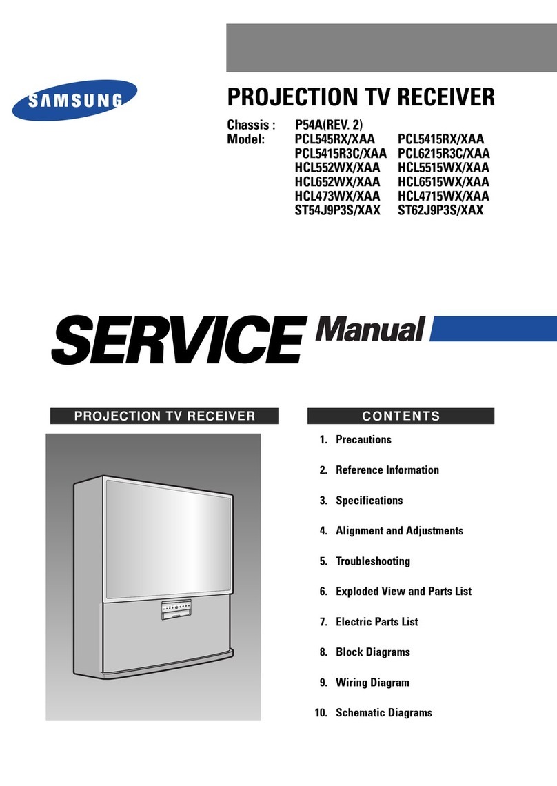
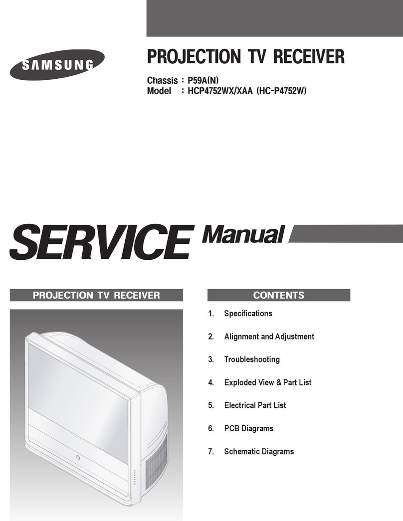
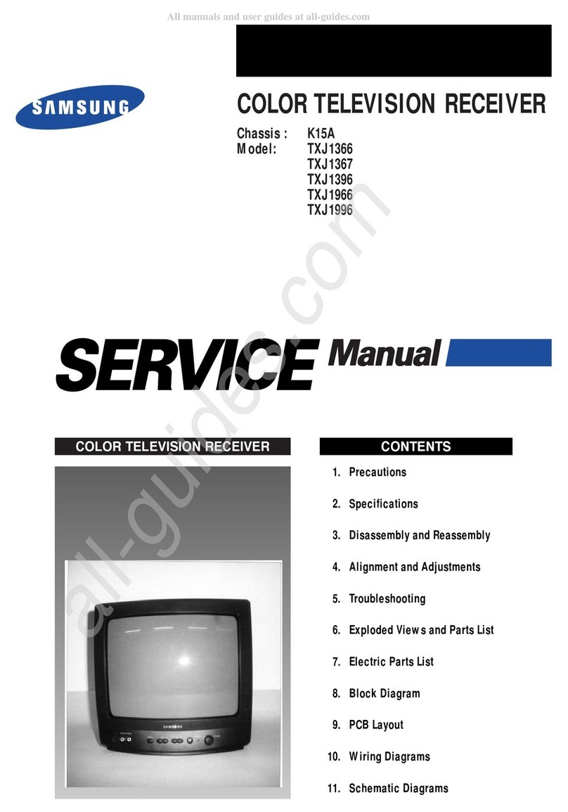
manuals.online logo
Brands
  1. Home
  2. •
  3. Brands
  4. •
  5. Samsung
  6. •
  7. TV Receiver
  8. •
  9. Samsung CT3338FX/XAP User manual

Samsung CT3338FX/XAP User manual

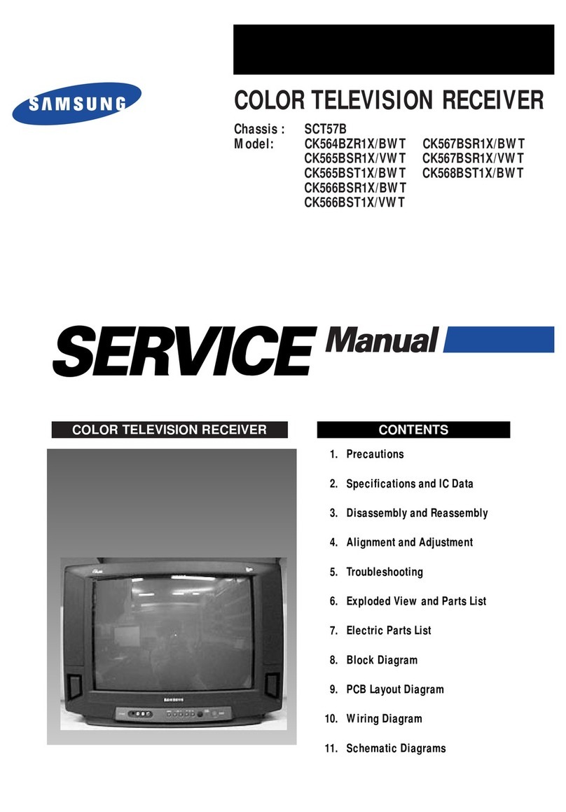
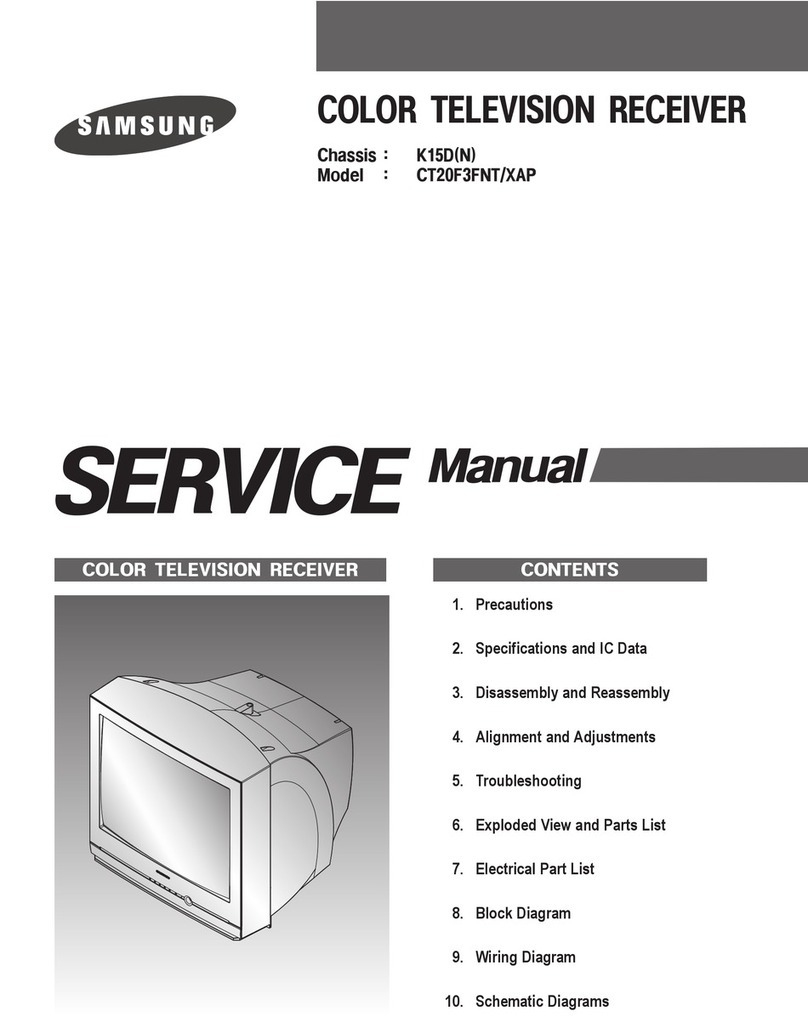
COLOR TELEVISION RECEIVER
Chassis : K15D
Model : CT3338FX/XAP
CT5038FX/XAP
CT2088BLFX/XAP
CT20D8BWFX/XAP
COLOR TELEVISION RECEIVER CONTENTS
Precautions
Specifications and IC Data
Disassembly and Reassembly
Alignment and Adjustment
Troubleshooting
Exploded View and Parts List
Electrical Parts List
Block Diagram
Wiring Diagram
Schematic Diagrams
1.
2.
3.
4.
5.
6.
7.
8.
9.
10.
ELECTRONICS
©Samsung Electronics Co., Ltd. SEP. 2002
Printed in Korea
AA82-00154A
Alignment and Adjustments
Samsung Electronics 4-1
4. Alignment and Adjustments
4-1 Preadjustment
4-1-1 Factory Mode
1. Do not attempt these adjustments in the Video
Mode.
2. The Factory Mode adjustments are necessary
when either the EEPROM (IC902) or the CRT
is replaced.
3. Do not tamper with the “Adjustment” screen
of the Factory Mode menu. This screen is
intended only for factory use.
4-1-2 When EEPROM (IC902) Is Replaced
1. When IC902 is replaced all adjustment data
revert to initial values. It is necessary to
re-program this data.
2. After IC902 is replaced, warm up the TV for
10 seconds.
4-1-3 When CRT Is Replaced
1. Make the following adjustments AFTER set-
ting up after setting up purity and conver-
gence :
White Balance
Sub-Brightness
Vertical Center
Vertical Size
Horizontal Size
Fail Safe (This adjustment must be the last
step).
2. If the EEPROM or CRT is replaced and set SC
as 20(factory mode).
4-2 Factory/Service Mode
4-2-1 Procedure for the “Adjustment” Mode
1. This mode uses the standard remote control.
The Service Mode is activated by entering the
following remote-control sequence :
(1) DISPLAY → FACTORY.
(2) STAND-BY → MUTE →1 →8 →2
→POWER ON.
2. The “SERVICE (FACTORY)” message will be
displayed. The Service Mode has four compo-
nents: ADJUST, OPTION , G2-ADJUST and
RESET.
3. Access the Adjustment Mode by pressing the
“VOLUME” keys ( Up or Down). The adjust-
ment parameters are listed in the accompany-
ing table, and selected by pressing the CHAN-
NEL keys ( , ).
4. Selection sequences for the all system:
DOWN or UP key:
SCT>SBT>BLR>BLB>RG>GG>BG>VSL>VS>
VA>HS>SC>CDL>STT>AKB>FS>NDL>
LBS>NSR>SCBT>VOL>CAP>HBS>RP00>
RP01>FMWS>AGC1>OMD>SCL>PWL>
MUS>AGC>DSK>DVDB
5. The VOLUME keys increase or decrease the
adjustment values (stored in the
non-volatile memory) when Adjustment Mode
is cancelled.
6. Cancel the Adjustment Mode by re-pressing
the “FACTORY” or “Power OFF” keys.
4-2-2 Main Adjustment Parameter
Alignment and Adjustments
4-2 Samsung Electronics
SCT Sub Cont ras t 0 ~ 23
0~23
SBT Sub Bright ness
BLR
Black Level offset Blue
BLB
Black Level offset Red
RG Red Gain 0 ~ 63
GG Green Gain 0 ~ 63
0~63
0~63
BG Blue Gai n 0 ~ 63
VSL Vert ical Slope 0 ~ 63
VS Ver t ical Shif t 0 ~ 63
VA Vert ical Am pli tud e 0 ~ 63
HS Horizontal Shif t 0 ~ 63
SC S- Cor r ec t i on 0 ~ 63
CDL Cat hode Drive Level 0 ~ 15
STT Sub Tint 0 ~ 7
AKB
FS
AKB On / off 0 ~ 1
0~1
0~1
0~1
0~1
0~1
00~1
0~3
0~3
Filter Seting
LBS Low Band Separation Set
0~15
0~15
0~15
NDL NTSC Delay 0 ~ 15
NSR NTSC Sub color 0 ~ 23
SCBT Screen Brighrtness 0 ~ 63
0~63
VOL Volume pre set t i ng 0 ~ 63
0~63
0~63
0~63
CAP Caption Position
High Band Separation Set
Ratio Pre / overshoot
Window Selection Sound PLL
IF AGC Speed
Offset IF Demodulator
Soft Clipping Level
Peak White Limitting
Matrix USA
Automatic Gain Control
Dynamic Skin Tone
DVD Bright Offset
HBS
RP00
RP01
FMWS
AGC1
OMD
SCL
PWL
MUS
AGC
DSK
DVDB
15
8
35
32
40
30
42
30
31
20
32
35
11
3
0
32
1
32
3
35
10
12
32
1
1
0
1
32
3
15
0
33
0
5
13
9
31
27
32
25
31
31
31
40
30
20
11
7
0
37
1
32
3
45
10
12
32
1
1
0
1
32
1
13
0
33
0
4
13
9
31
27
32
25
31
31
31
20
30
12
7
7
0
37
1
32
3
45
10
12
32
1
1
0
1
32
1
13
0
33
0
4
W/B (HIGH Y)
W/B A (LOW Y)
W/B (LOW X, Y)
W/B (LOW X, Y)
W/B (HIGH X, Y)
FIX
W/B (HIGH X, Y)
Vertical SLOPE
FIX
Vertical SIZE
Horizontal SHIFT
FIX
FIX
FIX
FIX
FIX(STEREO)
FIX
FIX(STEREO)
FIX
FIX
FIX
FIX
FIX(STEREO)
FIX
FIX
FIX (Mono)
FIX (Nomal)
FIX (No Crrection)
FIX (Off)
FIX (100%)
FIX (Mono)
FIX
FIX
FIX
1
2
3
4
5
6
7
8
9
10
11
12
13
14
15
16
17
18
19
20
21
22
23
24
25
26
27
28
29
30
31
32
33
34
OSDNO FUNCTION RANGE INITAL DATA
SETTING
19V 13V REMARK
Alignment and Adjustments
Samsung Electronics 4-3
4-2-3 Option Bytes
In the Service Mode, various can be selected via the Option Table. Example:
1
2
3
4
5
6
7
8
9
10
11
12
13
Option Table : xx xx
OSD
VIDEO MUTE
(When swiching channel)
AUDIO
TURBO
ZOOM
AUTO POWER ON
SOUND MUTE
(NO SIGNAL)
LANGUAGE
HOTEL MODE
CATV
X-RAY
V-CHIP
AV Option
DEMO
SETTING
ON
OFF
STEREO
LINE STEREO
MONO
ON
OFF
ZOOM
NOMAL
ON
OFF
OFF
ON
ENGLISH
ESPANOL
FRENCH/PORTU
OFF
ON
AIR/STD/HRC/IRC
AIR/STD/HRC/AFN
ON
OFF
ON
OFF
TV ↔ AV
TV ↔ AV ↔ DVD
ON
OFF
- 800msec Mute Time(Tri-norma)
- Unavailable
- Zenith stereo (WITH IN UPC1851B)
- Line stereo (WITH IN UPC1851B)
- Mono (WITH OUT UPC1851B)
- Stereo/L STEREO Model
- Mono Model
- Nornal / Zoom
- Nomal
- The power is switched on automatically
when detaching the Master S/W Auto On
- Tact S/W Model
- Unavailable
- Available
- Start Language Select
- Unavailable
- Available
- U.S Army
- Available (U.S.A, Army)
- Unavailable (South America)
- Available (U.S.A)
- Unavailable (Canada)
- Available (South America)
- Unavailable (U.S.A)
REMARK
Alignment and Adjustments
4-4 Samsung Electronics
4-3 Other Adjustments
4-3-1 General
1. Usually, a color TV needs only slight touch-
up adjustment upon installation. Check the
basic characteristics such as height, horizontal
and vertical sync and focus.
2. The picture should have good black and white
details. There should be no objectionable
color shading; if color shading is present, per-
form the purity and convergence adjustments
described below.
3. Use the specified test equipment or its equiva-
lent.
4. Correct impedance matching is essential.
5. Avoid overload. Excessive signal from a sweep
generator might overload the front-end of the
TV. When inserting signal markers, do not
allow the marker generator to distort test
results.
6. Connect the TV only to an AC power source
with voltage and frequency as specified on the
backcover nameplate.
7. Do not attempt to connect or disconnect any
wires while the TV is turned on. Make sure
that the power cord is disconnected before
replacing any parts.
8. To protect against shock hazard, use an isola-
tion transformer.
4-3-2 Automatic Degaussing
A degaussing coil is mounted around the pic-
ture tube, so that external degaussing after
moving the TV should be unnecessary. But
the receiver must be properly degaussed upon
installation.
The degaussing coil operates for about 1 sec-
ond after the power is switched ON. If the set
has been moved or turned in a different direc-
tion, disconnect its AC power for at least 30
minutes.
If the chassis or parts of the cabinet become
magnetized, poor color purity will result. If
this happens, use an external degaussing coil.
Slowly move the degaussing coil around the
faceplate of the picture tube and the sides and
front of the receiver. Slowly withdraw the coil
to a distance of about 6 feet before removing
power.
Alignment and Adjustments
Samsung Electronics 4-5
4-3-3 High Voltage Check
CAUTION: There is no high voltage adjustment on this chassis.
The B+ power supply must be set to +122.5 volts (Full color bar
input and normal picture level).
1. Connect a digital voltmeter to the second
anode of the picture tube.
2. Turn on the TV. Set the Brightness and
Contrast controls to minimum (zero beam cur-
rent).
3. The high voltage should not exceed 30KV.
4. Adjust the Brightness and contrast controls to
both extremes. Ensure that the high voltage
does not exceed 30KV under any conditions.
4-3-4 FOCUS Adjustment
1. Input a black and white signal.
2. Adjust the tuning control for the clearest pic-
ture.
3. Adjust the FOCUS control for well defined
scanning lines in the center area of the screen.
4-3-5 Cathode Voltage Adjustment
(Screen Adjustment)
1. Connect CRT socket pin GK to an oscilloscope
probe.
2. Input a gray scale pattern. (Use a pattern gen-
erator, PM5518)
3. Use the P mode key (on the remote control)
for the STANDARD picture.
4. Adjust the Screen VR (on the FBT) so that the
voltage on the oscilloscope becomes 125+2.5V
(See Fig. 4-1).
4-3-6 Purity Adjustment
1. Warm up the receiver for at least 20 minutes.
2. Plug in the CRT deflection yoke and tighten
the clamp screw.
3. Plug the convergence yoke into the CRT and
set in as shown in Fig. 4-2.
4. Input a black and white signal.
5. Fully demagnetize the receiver by applying an
external degaussing coil.
6. Turn the CONTRAST and BRIGHTNESS con-
trols to maximum.
7. Loosen the clamp screw holding the yoke.
Slide the yoke backward or forward to pro-
vide vertical green belt. (Fig. 4-3).
8. Tighten the convergence yoke.
9. Slowly move the deflection yoke forward,
and adjust for the best overall green screen.
10. Temporarily tighten the deflection yoke.
11. Produce blue and red rasters by adjusting the
low-light controls. Check for good purity in
each field.
12. Tighten the deflection yoke.
Fig. 4-1
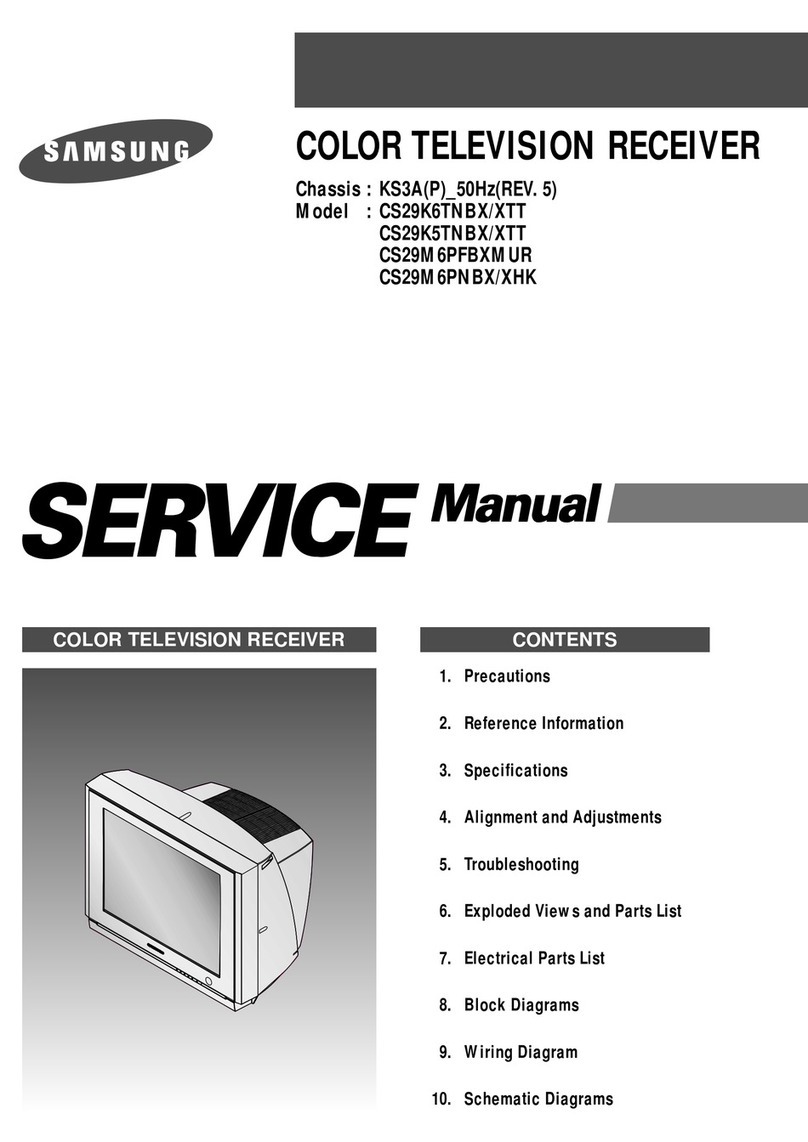
125 2.5V
+
_
GND
_
Alignment and Adjustments
4-6 Samsung Electronics
4-3-7 White Balance Adjustment
Fig. 4-2 Convergence Magnet Assembly
4 Pole Magnet
6 Pole Magnet 2 Pole Magnet
Clamper
Screw
2 POLE
PURITY
YOKE
CLAMP
SCREW
6 POLE
CONVERGENCE
4 POLE
CONVERGENCE
ADJU
(VERT
Fig. 4-3 Center Convergence Adjustment
31m/m
Vertical Green Belt
Fig. 4-4
1
2
(a) Set up
1. Warm up the TV for at least 30 minutes in the
Aging Mode (OSD White). This mode is dis-
played by entering the following sequence:
DISPLAY →FACTORY →FACTORY
2. Input a Toshiba pattern.
(b) Low-Light Adjustment
1. Set SBT to 1.2 fL in the Factory Service
Mode with using CA100. See Fig. 4-4.
2. Adjust RG,BG so that the levels are suitable to
each local area.
(c) High-Light Adjustment
1. Set SCT to 50FL(13V : 60FL) in the Factory
Service Mode with using CA100.
See Fig. 4-4 .
Alignment and Adjustments
Samsung Electronics 4-7
4-3-8 Center Convergence Adjustment
1. Warm up the receiver for at least 20 minutes.
2. Adjust the two tabs of the 4 pole magnets to
change the angle between them. Superimpose
the red and blue vertical lines in the center
area of the screen.
3. Adjust the Brightness and Contrast controls
for a well defined picture.
4. Adjust the two-tab pairs of the 4 pole mag-
nets, and change the angle between them.
Superimpose the red and the blue vertical
lines in the center area of the screen.
5. Turn the both tabs at the same time, keeping
the angle constant, and superimpose the red
and blue horizontal line in the center of the
screen.
6. Adjust the two-tab pairs of the 6-pole magnets
to superimpose the red and blue line onto the
green. (Changing the angle affects the vertical
lines, and rotating both magnets affects the
horizontal lines.)
7. Repeat adjustments 2~6, if necessary.
8. Since the 4-pole magnets and 6-pole magnets
interact, the dot movement is complex
(Fig. 4-5).
Fig. 4-5 Center Convergence Adjustment
RED
BLUE
BLUE
RED
4-Pole Magnet Movement
GREEN
RED/BLUE
RED/BLUE
GREEN
6-Pole Magnet Movement
4-3-9 RF AGC Adjustment
Set the AGC data to 33 (Factory Mode).
4-3-10 Sub-Color Adjustment
Set NSR data to 3 (Factory Mode).
4-3-11 Geometry Adjustment
SC →VS→VA→VSL→HS
1. Input a lion head pattern.
2. Set the SC (S-Correction) as 20(13V : 12) and
VS(Vertical Shift) 31 so that the lion head circle
becomes oval.
3. Adjust with VA (Vertical Amplitude) so that
the top margin of the picture is 4.
Fig. 4-7
4. Adjust with VSL (Vertical-Slope) so that the
bottom margin of the picture is 4.
Fig. 4-8
5. Adjust with HS (Horizontal Shift) so that the
lion-head pattern and CRT centers are aligned.
Fig. 4-9
6. Adjust HS (Horizontal Shift) so that the left
and right margins of the picture are 5.
Alignment and Adjustments
4-8 Samsung Electronics
4
55
4
6. Exploded View & Parts List
6-1 CT3338FX/XAP
Exploded View & Parts List
Samsung Electronics 6-1
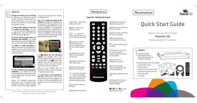
1-1
1-2 1-3 1-4
1-5
1-8
1-6
1-7
2
2-2
2-1
3
4
3-2
3-1
1 AA64-31147Q CABINET FRONT;3338,SV704P EPPV,HIPS,HB,G 1 F/C
1-1 INLAY-A/V
1-2 AA64-70127F BADGE-BRAND;AL,SS,SILVER,R800 1 BADGE
1-3 AA64-40057A WINDOW-REMOCON;-,ABS,HB,-,-,33 1 WR
1-4 AA64-10153J KNOB POWER;3338,ABS,-,G3676,NO-SILK,HB,- 1 KP
1-5 AA61-60003J SPRING-CS;-,-,SUS304,0.5,OD6,H 1 SPRING
1-6 6003-001026 SCREW-TAPTITE;RH,+,B,M4,L15,ZPC(BLK),SWR 1 KC+CF
1-7 AA64-10052B KNOB-CONTROL;-,3338,G3676 JPN,ABS,HB,GRA 1 KC
1-8 AA96-00144A ASSY-SPEAKER;-,8OHM,2.5WX2,3001-000281,A 1 A/SPK
1-9 AA61-40010A BOSS-CABINET;-,HIPS,HB,BLK, 2 BOSS
2 AA03-10002M CRT-COLOR;-,A34KQV42X,0MG,14, 1 CRT
2-1 AA61-00735A HOLDER;20POLYVINIL,DEGAUSSING,CHLORI 2 CDCOIL
2-2 AA60-10050Q SCREW-ASSY;WC,HH,M5,L26.5,SWRCH, 4 CRT+CF
3 AA64-00170A CABINET-BACK;,HIPS,HB,G4309 1 B/C
3-1 AA42-00004A ANT ROD;VHF,4SDODIPOLE850MMBRN 1 A/ROD
3-2 6003-001026 SCREW-TAPTITE;RH,+,B,M4,L15,ZPC(BLK),SWR 4 CB+CF
4 AA96-00669A ASSY POWER CORD;,CP2 N/P,H/C250,AA61-200 1 PWR/AC
No Code No Description;Specification Q’ty Remark
Exploded View & Parts List
6-2 Samsung Electronics
6-2 CT5038FX/XAP
1 AA64-31263V CABINET-FRONT;5038,SV704P,PV,HB,GRYK15AH 1 F/C
1-1 INLAY-AV 1
1-2 AA64-70127F BADGE-BRAND;AL,SS,SILVER,R800 1 BADGE
1-3 AA64-40085A WINDOW-REMOCON;-,ABS,HB,-,NO-S 1 WR
1-4 AA64-10187G KNOB POWER;5038,ABS,-,G3676,NO-SILK,HB,- 1 KP
1-5 AA61-60003J SPRING-CS;-,-,SUS304,0.5,OD6,H 1 SPRING
1-6 AA63-50057B GRILLE-WOOFER;DP,5038,AA63-50056B,-,-,-, 1 GRILL
1-7 AA61-40007A STOPPER-PCB;-,ABSHB,-,-,NTR,50 1 STOPER
1-8 ASS’Y-A/V FRONT 1
1-9 6006-001095 SCREW-ASS’Y TAPT;WP,BH,+,M4,L12,ZPC(YEL) 2 PA+CF
1-10 AA64-40188A INDICATOR-LED;-,ACRYL,-,-,-,50 1
1-11 AA96-10141B ASSY-SPEAKER;-,8OHM,3W,3001-001020,AA39- 1 A/SPK
1-12 6003-001026 SCREW-TAPTITE;RH,+,B,M4,L15,ZPC(BLK),SWR 2 SPK+CF
1-14 AA61-40010A BOSS-CABINET;-,HIPS,HB,BLK, 2 BOSS
2 AA03-00246A CRT-COLOR;A48KRD82X(H)+380MG,NONAFTA,MAL 1 CRT
2-1 AA61-00734A HOLDER;25POLYVINYL,DEGAUSSING,CHLORI 2 CDCOIL
2-2 AA60-10050R SCREW-ASSY;WC,HH,+M5,L31.5,SWR 4 CRT+CF
3 AA64-30775G CABINET-BACK;HIPS,HB,G4309,5073 1 B/C
3-1 AA42-00004A ANT ROD;VHF,4SDODIPOLE850MMBRN 1 A/ROD
3-2 6003-001026 SCREW-TAPTITE;RH,+,B,M4,L15,ZPC(BLK),SWR 4 CB+CF
3-3 AA96-00669A ASSY POWER CORD;,CP2 N/P,H/C250,AA61-200 1 PWR/AC
No Code No Description;Specification Q’ty Remark
Exploded View & Parts List
Samsung Electronics 6-3
6-3 CT2088BLFX/XAP
1 AA64-00700D CABINET FRONT;-,20S4,SV704P PGB2000,HIPS 1 F/C
1-1 AA64-00704B WINDOW REMOCON;-,20S4,-,PC,V0,VIOLET,- 1 WR
1-2 AA64-00703D KNOB POWER;-,20S4,T/S NO-SILK,ABS,HB,G36 1 KP
1-3 AA61-60003J SPRING-CS;-,-,SUS304,0.5,OD6,H 1 SPRING
1-4 AA64-00705B INDICATOR LED;-,20S4,-,ACRYL,-,CLR,- 1 IL
1-5 AA64-70123B BADGE-BRAND;AL,R2000,SILVER,L=50,SAMSUNG 1 BADGE
1-6 AA63-00270A GRILLE-WOOFER,L;DP,20S4,63-00204B 11.5kg 1 GRILLE
AA63-00271A GRILLE-WOOFER,R;DP,20S4,63-00205B 11.5kg 1 GRILLE
1-7 AA63-00202C COVER-CONTROL;-,20S4,GD906P EPG NT,HIPS, 1 CC
1-8 AA63-00226B COVER-TOP,LATIN;-,20S4,T/SOUND,ABS,LG TR 1 C-TOP
1-9 AA95-00577A ASSY-PCB,A/V FRONT;CT2188BL6,K15A,STR 1 A/A-V
1-10 AA65-30105A CLAMP-WIRE;NYLON 66N,VO,NTR,15MM 1
1-11 AA64-00702B KNOB CONTROL;-,20S4,-,ABS,HB,G3676 1 KC
1-12 6003-001026 SCREW-TAPTITE;RH,+,B,M4,L15,ZPC(BLK),SWR 1 KC+CF
1-13 AA96-00287A ASSY SPEAKER;-,8ohm,15W,001115/001088,AA 1 A/SPK
1-14 6003-001026 SCREW-TAPTITE;RH,+,B,M4,L15,ZPC(BLK),SWR 12 SPK+CF
2 AA03-00246A CRT-COLOR;A48KRD82X(H)+380MG,NONAFTA,MAL 1 CRT
2-1 AA61-00734A HOLDER;25POLYVINYL,DEGAUSSING,CHLORI 2 CDCOIL
2-2 AA60-10050R SCREW-ASSY;WC,HH,+M5,L31.5,SWR 4 CRT+CF
2-3 3704-001105 SOCKET-CRT;11P,20PI,26.5PI,NI,- 1 V999S
3 AA64-00701F CABINET BACK;20S4,HIPS,HB,G4309 1 B/C
3-1 6003-001026 SCREW-TAPTITE;RH,+,B,M4,L15,ZPC(BLK),SWR 6 CB+CF
3-2 AA42-00004A ANT ROD;VHF,4SDODIPOLE850MMBRN 1 A/ROD
4 AA96-20109C ASSY PWR-CORD;CP2/NO(4.0)H/C300,KKP419C, 1 PWR/AC
No Code No Description;Specification Q’ty Remark
Exploded View & Parts List
6-4 Samsung Electronics
6-4 CT20D8BWFX/XAP
1 AA64-01028A CABINET FRONT;TOOL,20D8,MOLD,-,-,-,-,- 1 C/F
1-1 AA64-70123B BADGE-BRAND;AL,R2000,SILVER,L=50,SAMSUNG 1 BADGE
1-2 AA64-01030A KNOB POWER;TOOL,20D8,MOLD,-,-,- 1 KP
1-3 AA61-60003J SPRING-CS;-,-,SUS304,0.5,OD6,H 1 SPRING
1-4 AA95-00577A ASSY-PCB,A/V FRONT;CT2188BL6,K15A,STR 1 A/A-V
1-5 AA65-30018A CLAMP-WIRE;-,NYLON6.6,-,-,DATL 1 CWIRE1
1-6 AA61-40113A STOPPER-PCB;-,ABS,HB,NTR. 1 STOPPE
1-7 AA64-01032A INDICATOR LED;TOOL,20D8,MOLD,-,-,-,- 1 IL
1-8 AA64-01031A WINDOW REMOCON;MOLD,20D8,MOLD,-,-,-,- 1 WR
1-9 6003-001026 SCREW-TAPTITE;RH,+,B,M4,L15,ZPC(BLK),SWR 1 IL+CF
1-10 3001-001038 SPEAKER;6W,16OHM,92DB,140HZ 2 SPK
1-11 6003-001026 SCREW-TAPTITE;RH,+,B,M4,L15,ZPC(BLK),SWR 8 SPK+CF
1-12 AA64-01033A KNOB CONTROL;TOOL,20D8,MOLD,-,-,- 1 KC
1-13 6003-001026 SCREW-TAPTITE;RH,+,B,M4,L15,ZPC(BLK),SWR 1 KC+CF
2 AA03-00246A CRT-COLOR;A48KRD82X(H)+380MG,NONAFTA,MAL 1 CRT
2-1 AA61-00734A HOLDER;25POLYVINYL,DEGAUSSING,CHLORI 2 CDCOIL
2-2 AA60-10050R SCREW-ASSY;WC,HH,+M5,L31.5,SWR 4 CRT+CF
2-3 3704-001105 SOCKET-CRT;11P,20PI,26.5PI,NI,- 1 V999S
3 AA64-00186A CABINET-BACK;,HIPS,HB,G4309 1 B/C
3-1 6003-001026 SCREW-TAPTITE;RH,+,B,M4,L15,ZPC(BLK),SWR 4 CB+CF
3-2 AA96-20109C ASSY PWR-CORD;CP2/NO(4.0)H/C300,KKP419C, 1 PWR/AC
No Code No Description;Specification Q’ty Remark
TP06 TP05 TP04
TP02
TP03 TP01
Schematic Diagrams
10-1Samsung Electronics
10. Schematic Diagrams
10-1 MAIN (1/4)
TP01
TP02
TP03
TP04
TP05
TP06
Schematic Diagrams
10-2 Samsung Electronics
10-2 MAIN (2/4)
TP08
TP07
TP11
TP10
TP09
TP07
TP08
TP09
TP10
TP11
Schematic Diagrams
10-3Samsung Electronics
10-3 MAIN (3/4)
TP08
TP07
TP07
TP08
: Power Line
: Signal Line
Schematic Diagrams
10-4 Samsung Electronics
10-4 MAIN (4/4)
Electrical Parts List
Samsung Electronics 7-1
Loc. No. Code No. Description ; Specification Remark Loc. No. Code No. Description ; Specification Remark
ASSY CHASSIS
1 A/CHAS AA91-05816A ASSY CHASSIS;K15D,14,F/V,MONO,LATI,CT33
2 CLW/HS AA65-30018A CLAMP-WIRE;-,NYLON6.6,-,-,DATL
2 FBT AA65-30018A CLAMP-WIRE;-,NYLON6.6,-,-,DATL
2 A/MAIN AA96-01083A ASSY PCB P-MAIN;K15D,13,MONO,LATIN,CT33
3 Q401 0502-001115 TR-POWER;KSC5386,NPN,50W,TO-3PF,ST,8
3 IC902 1103-001209 IC-EEPROM;AT24C04-PC27 C,512Kx8Bit,DIP,8
3 CR401S 2303-001015 C-FILM,PPFF;5.5NF,5%,1.6KV,TP,
3 SF101S 2904-001221 FILTER-SAW AV,45.75MHz,SIP5K,ST,14.2dB,M
3 SWN01 3404-000295 SW-TACT,V;KPT1122R1KEYSTT=0.3M
3 FP801S 3601-001012 FUSE-FERRULE;250V,4A,SLOW-BLOW
3 V999S 3704-001089 SOCKET CRT;9P,22.5PI,12PI,SN,13
3 CN704 3711-002646 POST-HEADER;67094-007(AUTO)
3 JA701 3722-000162 JACK-PIN;2P,3.4MM,-,SN
3 IC201S AA09-00318A IC MICOM;TDA9377PS/N2/AI,SPM-458AN1,64P,
3 T801S AA26-00172A TRANS-SWITCHING;EER3543,K15D,90~264,PM2A
3 T444S AA26-00065A TRANS FBT;-,FSV-14A004C(S),14-22,125V
3 T401 AA26-50001B ORIZ.DRIVE;-,7.1MH,102UH,10-2
3 LR401S AA27-00053A COIL-LINEARLITY;-,193uH,DR10X10 C:4.35,7
3 LX801S AA29-30001D FILTER-LINE;-,6.0MH,2A,-,SQ191
3 RM901 AA32-00015A MODULE-REMOCON;FRP-3521H31,38KHZ,940MM,M
3 CN501 AA39-20620A LEADCONNECTOR-ASSY;-,YBNH025-09,S,9P,30
3 TU01S AA40-00073A TUNER-TECC1040PG32A(S),181CH,45.75MHZ,75
3 IC301 AA96-00244A ASSY H/S;-,-,AA62-00046A,LA7840,-
4 0205-000129 GREASE-SILICON;SC102,JAPAN
4 1204-001483 IC-VERTICAL PROCESSO;LA7840,SIP,7P,708MI
4 6003-000335 SCREW-TAPTITE;RH,+,2S,M3,L8,ZPC(YEL),SWR
4 AA62-00046A HEAT SINK-PS;-,-,T1.0,-,D1(DREAM) 60X25X
3 IC601 AA96-00244D ASSY H/S;-,SOUND,AA62-00046A,TDA7266M,-
4 0205-000129 GREASE-SILICON;SC102,JAPAN
4 1201-001600 IC-AUDIO AMP;7266,ZSIP,15P,-,SINGLE,26dB
4 6003-000335 SCREW-TAPTITE;RH,+,2S,M3,L8,ZPC(YEL),SWR
4 AA62-00046A HEAT SINK-PS;-,-,T1.0,-,D1(DREAM) 60X25X
3 IC802 AA96-00245A ASSY H/S;-,-,AA62-00055A,KA7632,-
4 1203-001939 IC-POSI.FIXED REG.;7632,SIP,10P,-,PLASTI
4 6003-000334 SCREW-TAPTITE;RH,+,2S,M3,L6,ZP
4 AA62-00055A HEAT SINK-PS;-,-,T1.0,-,35*15*25,D1,-,-,
3 LD901 AA96-00555A ASSY LED GUIDE;-,-,UEX-LD-030,GREEN
3 IC501 AA96-50311A ASSY-H/S;-,VIDEO,AA62-30175D,TDA6107Q,-
4 1201-001159 ICVIDEOAMP;TDA6107Q,ZIP,9P,300
4 6003-000334 SCREW-TAPTITE;RH,+,2S,M3,L6,ZP
4 AA62-30175D HEATSINK-PS;-,SECC,T1.0,-,33X15X30FT-2
3 IC801S AA96-00816A ASSY H/S;,POWER,AA62-00112A,5Q0765RT,TR
4 0205-000129 GREASE-SILICON;SC102,JAPAN
4 1203-001932 IC-PWM CONTROLLER;5Q0765,TO-220F,5P,185M
4 6003-000335 SCREW-TAPTITE;RH,+,2S,M3,L8,ZPC(YEL),SWR
4 AA62-00112A HEAT SINK;TROJAN,AL1050 ,T2.0,W54.0,H40.
3 A/AUTO AA97-13307A ASSY AUTO-MAIN;,K15D,CT14F2FX(LATIN)
4 D201 0401-000005 DIODE;1N4148,100V,300mA,1V,8nS,TAPING
4 D601 0401-000005 DIODE;1N4148,100V,300mA,1V,8nS,TAPING
4 D811 0401-000005 DIODE;1N4148,100V,300mA,1V,8nS,TAPING
4 D303 0402-000132 DIODE-RECTIFIER;1N4004,400V,1A,DO-41
4 D809 0402-000132 DIODE-RECTIFIER;1N4004,400V,1A,DO-41
4 D501 0402-000254 DIODE-RECTIFIER;RGP10J,600V,1A,DO-41
4 D807 0402-000493 DIODE-RECTIFIER;1R5GU41,400V,1
4 D302 0402-000534 DIODE-RECTIFIER;RG10V,400V,1.5
4 D805 0402-001443 DIODE-RECTIFIER;EGP20K,800V,2A,DO-15,TP
4 D301 0402-001105 DIODE-RECTIFIER;ERB43-04SV1,400V,1.0A,-,
4 D304 0402-001105 DIODE-RECTIFIER;ERB43-04SV1,400V,1.0A,-,
4 D401 0402-001105 DIODE-RECTIFIER;ERB43-04SV1,400V,1.0A,-,
4 D502 0402-001105 DIODE-RECTIFIER;ERB43-04SV1,400V,1.0A,-,
4 D503 0402-001105 DIODE-RECTIFIER;ERB43-04SV1,400V,1.0A,-,
4 D504 0402-001105 DIODE-RECTIFIER;ERB43-04SV1,400V,1.0A,-,
4 D812 0402-001105 DIODE-RECTIFIER;ERB43-04SV1,400V,1.0A,-,
4 D801S 0402-001111 DIODE-RECTIFIER;1N5397GP,600V,1.5A,DO-2
4 D802S 0402-001111 DIODE-RECTIFIER;1N5397GP,600V,1.5A,DO-2
4 D803S 0402-001111 DIODE-RECTIFIER;1N5397GP,600V,1.5A,DO-2
4 D804S 0402-001111 DIODE-RECTIFIER;1N5397GP,600V,1.5A,DO-2
4 DZ211 0403-000508 DIODE-ZENER;MTZJ5.6B,5.6V,5.45-5.73V,500
4 DZ401 0403-000508 DIODE-ZENER;MTZJ5.6B,5.6V,5.45-5.73V,500
4 DZ402 0403-000508 DIODE-ZENER;MTZJ5.6B,5.6V,5.45-5.73V,500
4 DZ903 0403-000508 DIODE-ZENER;MTZJ5.6B,5.6V,5.45-5.73V,500
4 DZ904 0403-000508 DIODE-ZENER;MTZJ5.6B,5.6V,5.45-5.73V,500
4 DZ905 0403-000508 DIODE-ZENER;MTZJ5.6B,5.6V,5.45-5.73V,500
4 DZ803 0403-000167 DIODE-ZENER;1N4758A,56V,5%,1W,DO-41,TP
4 DZ101 0403-000700 DIODE-ZENER;TZP33A,33V,31-35V,
4 DZ303 0403-000700 DIODE-ZENER;TZP33A,33V,31-35V,
4 DZ604 0403-000719 DIODE-ZENER;MTZJ7.5B,7.5V,7.07-7.45V,500
4 DZ201 0403-000720 DIODE-ZENER;MTZJ9.1B,9.1V,8.57-9.01V,500
4 DZ202 0403-000720 DIODE-ZENER;MTZJ9.1B,9.1V,8.57-9.01V,500
4 DZ205 0403-000720 DIODE-ZENER;MTZJ9.1B,9.1V,8.57-9.01V,500
4 DZ306 0403-000720 DIODE-ZENER;MTZJ9.1B,9.1V,8.57-9.01V,500
4 DZ307 0403-000720 DIODE-ZENER;MTZJ9.1B,9.1V,8.57-9.01V,500
4 DZ501 0403-000720 DIODE-ZENER;MTZJ9.1B,9.1V,8.57-9.01V,500
4 DZ502 0403-000720 DIODE-ZENER;MTZJ9.1B,9.1V,8.57-9.01V,500
4 DZ503 0403-000720 DIODE-ZENER;MTZJ9.1B,9.1V,8.57-9.01V,500
4 DZ504 0403-000720 DIODE-ZENER;MTZJ9.1B,9.1V,8.57-9.01V,500
4 DZ806 0403-000720 DIODE-ZENER;MTZJ9.1B,9.1V,8.57-9.01V,500
4 DZ807 0403-000720 DIODE-ZENER;MTZJ9.1B,9.1V,8.57-9.01V,500
4 DZ808 0403-000720 DIODE-ZENER;MTZJ9.1B,9.1V,8.57-9.01V,500
4 DZ801 0403-001140 DIODE-ZENER;RD10ESAB-T4,10V,9.19-10.30V,
4 DZ204 0403-001211 DIODE-ZENER;MTZJ12B,11.44-12.03V,500MW,D
4 DZ302 0403-001221 DIODE-ZENER;UZ39BSB,35.36-37.19V,500MW,D
4 DZ802 0403-001318 DIODE-ZENER;MTZJ4.3B,4.17-4.43V,500mW,DO
4 DZ901 0403-001373 DIODE-ZENER;MTZJ5.1A,4.81V-5.07V,500mW,D
4 DZ805 0403-001327 DIODE-ZENER;MTZJ18A,16.22-17.06V,500mW,D
4 DZ301 0403-001328 DIODE-ZENER;MTZJ22A,20.15-21.20V,500mW,D
4 DZ305 0403-001328 DIODE-ZENER;MTZJ22A,20.15-21.20V,500mW,D
4 Q201 0501-000283 TRANSISTOR;KSA539-Y(TAPG)/YTAM
4 Q901 0501-000283 TRANSISTOR;KSA539-Y(TAPG)/YTAM
4 Q402 0501-000369 TRANSISTOR;KSC2331-Y(TAPG)
4 Q202 0501-002183 TR-SMALL SIG;KTC9014,NPN,625MW,TO-92,100
4 Q601 0501-002183 TR-SMALL SIG;KTC9014,NPN,625MW,TO-92,100
4 R207 2001-000005 R-CARBON;390OHM,5%,1/8W,AA,TP,
4 R905 2001-000005 R-CARBON;390OHM,5%,1/8W,AA,TP,
4 R906 2001-000005 R-CARBON;390OHM,5%,1/8W,AA,TP,
4 R206 2001-000010 R-CARBON;68Kohm,5%,1/8W,AA,TP,1.8x3.2mm
4 R301 2001-000016 R-CARBON(S);1OHM,5%,1/2W,AA,TP
4 R843 2001-000019 R-CARBON(S);10ohm,5%,1/2W,AA,TP,2.4x6.4m
4 R409 2001-000022 R-CARBON(S);33OHM,5%,1/2W,AA,T
4 R823 2001-000037 R-CARBON(S);330OHM,5%,1/2W,AA,
4 R808 2001-001138 R-CARBON(S);390OHM,5%,1/2W,AA,
4 R902 2001-000241 R-CARBON;1.5KOHM,5%,1/8W,AA,TP
4 R904 2001-000241 R-CARBON;1.5KOHM,5%,1/8W,AA,TP
4 R287 2001-000273 R-CARBON;100KOHM,5%,1/8W,AA,TP
4 R211 2001-000281 R-CARBON;100OHM,5%,1/8W,AA,TP,
4 R233 2001-000281 R-CARBON;100OHM,5%,1/8W,AA,TP,
4 R501 2001-000281 R-CARBON;100OHM,5%,1/8W,AA,TP,
4 R502 2001-000281 R-CARBON;100OHM,5%,1/8W,AA,TP,
4 R506 2001-000281 R-CARBON;100OHM,5%,1/8W,AA,TP,
4 R510 2001-000281 R-CARBON;100OHM,5%,1/8W,AA,TP,
4 R511 2001-000281 R-CARBON;100OHM,5%,1/8W,AA,TP,
4 R512 2001-000281 R-CARBON;100OHM,5%,1/8W,AA,TP,
4 R909 2001-000281 R-CARBON;100OHM,5%,1/8W,AA,TP,
4 R911 2001-000281 R-CARBON;100OHM,5%,1/8W,AA,TP,
4 R912 2001-000281 R-CARBON;100OHM,5%,1/8W,AA,TP,
4 R913 2001-000281 R-CARBON;100OHM,5%,1/8W,AA,TP,
4 R914 2001-000281 R-CARBON;100OHM,5%,1/8W,AA,TP,
4 R917 2001-000281 R-CARBON;100OHM,5%,1/8W,AA,TP,
4 R933 2001-000281 R-CARBON;100OHM,5%,1/8W,AA,TP,
4 R934 2001-000281 R-CARBON;100OHM,5%,1/8W,AA,TP,
4 R942 2001-000281 R-CARBON;100OHM,5%,1/8W,AA,TP,
4 R943 2001-000281 R-CARBON;100OHM,5%,1/8W,AA,TP,
4 R291A 2001-000290 R-CARBON;10KOHM,5%,1/8W,AA,TP,
4 R601 2001-000290 R-CARBON;10KOHM,5%,1/8W,AA,TP,
4 R612 2001-000290 R-CARBON;10KOHM,5%,1/8W,AA,TP,
7-1 CT3338FX/XAP
7. Electrical Parts List
Electrical Parts List
7-2 Samsung Electronics
4 R828 2001-000290 R-CARBON;10KOHM,5%,1/8W,AA,TP,
4 R910 2001-000290 R-CARBON;10KOHM,5%,1/8W,AA,TP,
4 R606 2001-000290 R-CARBON;10KOHM,5%,1/8W,AA,TP,
4 R224 2001-000290 R-CARBON;10KOHM,5%,1/8W,AA,TP,
4 R225 2001-000325 R-CARBON;120OHM,5%,1/8W,AA,TP,
4 R205 2001-000397 R-CARBON;180KOHM,5%,1/8W,AA,TP
4 R218 2001-000411 R-CARBON;18KOHM,5%,1/8W,AA,TP,
4 R602 2001-000429 R-CARBON;1Kohm,5%,1/8W,AA,TP,1.8x3.2mm
4 R604 2001-000429 R-CARBON;1Kohm,5%,1/8W,AA,TP,1.8x3.2mm
4 R926 2001-000429 R-CARBON;1Kohm,5%,1/8W,AA,TP,1.8x3.2mm
4 R944 2001-000429 R-CARBON;1Kohm,5%,1/8W,AA,TP,1.8x3.2mm
4 R918 2001-000449 R-CARBON;2.2KOHM,5%,1/8W,AA,TP
4 R940 2001-000449 R-CARBON;2.2KOHM,5%,1/8W,AA,TP
4 R941 2001-000449 R-CARBON;2.2KOHM,5%,1/8W,AA,TP
4 R220 2001-000472 R-CARBON;2.7KOHM,5%,1/8W,AA,TP
4 R901 2001-000472 R-CARBON;2.7KOHM,5%,1/8W,AA,TP
4 R903 2001-000472 R-CARBON;2.7KOHM,5%,1/8W,AA,TP
4 R907 2001-000472 R-CARBON;2.7KOHM,5%,1/8W,AA,TP
4 R908 2001-000472 R-CARBON;2.7KOHM,5%,1/8W,AA,TP
4 R607 2001-000472 R-CARBON;2.7KOHM,5%,1/8W,AA,TP
4 R214 2001-000490 R-CARBON;200OHM,5%,1/8W,AA,TP,
4 R829 2001-000563 R-CARBON;27KOHM,5%,1/8W,AA,TP,1.8X3.2MM
4 R208 2001-000591 R-CARBON;3.3KOHM,5%,1/8W,AA,TP
4 R202 2001-000689 R-CARBON;390KOHM,5%,1/8W,AA,TP
4 R925 2001-000734 R-CARBON;4.7KOHM,5%,1/8W,AA,TP
4 R708 2001-000734 R-CARBON;4.7KOHM,5%,1/8W,AA,TP
4 R227 2001-000739 R-CARBON;4.7MOHM,5%,1/8W,AA,TP
4 R228 2001-000739 R-CARBON;4.7MOHM,5%,1/8W,AA,TP
4 R109 2001-000786 R-CARBON;47KOHM,5%,1/8W,AA,TP,
4 R927 2001-000793 R-CARBON;47OHM,5%,1/8W,AA,TP,1
4 R203 2001-000857 R-CARBON;560OHM,5%,1/8W,AA,TP,
4 R110 2001-000924 R-CARBON;680ohm,5%,1/8W,AA,TP,1.8x3.2mm
4 R915 2001-000924 R-CARBON;680ohm,5%,1/8W,AA,TP,1.8x3.2mm
4 R108 2001-000947 R-CARBON;7.5KOHM,5%,1/8W,AA,TP
4 R222 2001-000947 R-CARBON;7.5KOHM,5%,1/8W,AA,TP
4 R605 2001-000947 R-CARBON;7.5KOHM,5%,1/8W,AA,TP
4 R212 2001-000969 R-CARBON;75OHM,5%,1/8W,AA,TP,1
4 R215 2001-000969 R-CARBON;75OHM,5%,1/8W,AA,TP,1
4 R610 2001-000969 R-CARBON;75OHM,5%,1/8W,AA,TP,1
4 R408 2001-001037 R-CARBON(S);0.39OHM,5%,1/2W,AA
4 R504 2001-001062 R-CARBON(S);10MOHM,5%,1/2W,AA,
4 R414 2001-001078 R-CARBON(S);15KOHM,5%,1/2W,AA,
4 R840 2001-001108 R-CARBON(S);22KOHM,5%,1/2W,AA,
4 R411 2001-001114 R-CARBON(S);270OHM,5%,1/2W,AA,
4 R405 2001-001195 R-CARBON(S);82OHM,5%,1/2W,AA,T
4 R503 2002-001008 R-COMPOSITION;1.8KOHM,10%1/2W,AA,TP,3.7
4 R501M 2002-001008 R-COMPOSITION;1.8KOHM,10%1/2W,AA,TP,3.7
4 R502M 2002-001008 R-COMPOSITION;1.8KOHM,10%1/2W,AA,TP,3.7
4 RY801S 2002-001013 R-COMPOSITION;4.7MOhm,5%,1/2W,AA,TP,3.7X
4 R402 2003-002178 R-METAL OXIDE(S) 1Kohm,5%,2W,AG,TP,3.9X1
4 R316 2003-002009 R-METALOXIDE(S);390OHM,5%,2W,A
4 R413 2003-000664 R-METAL OXIDE(S);330HM,5%,2W,AF,TP,4X12M
4 R403 2003-002173 R-METAL OXIDE(S);7.5Kohm,5%,2W,AG,TP,3.9
4 R827 2003-000998 R-METALOXIDE;300OHM,5%,2W,AF,T
4 R407 2003-001040 R-METALOXIDE(S);47Kohm,5%,2W,AF,TP,3.9x1
4 R834 2003-001040 R-METALOXIDE(S);47Kohm,5%,2W,AF,TP,3.9x1
4 R603 2004-000195 R-METAL;100Kohm,1%,1/8W,AA,TP,1.8x3.2m
4 R423 2004-004089 R-METAL;123KOHM,1%,1/2W,AA,TP,2.5X6.5
4 R302 2004-001390 R-METAL(S);1KOHM,2%,1/2W,AA,TP
4 R306 2004-001390 R-METAL(S);1KOHM,2%,1/2W,AA,TP
4 R424 2004-001402 R-METAL(S);6.8KOHM,1%,1/2W,AA,
4 R219 2004-001914 R-METAL;39KOHM,2%,1/8W,AA,TP,1
4 R304 2008-000253 R-FUSIBLE(S);0.47OHM,5%,1W,AF,
4 R305 2008-000253 R-FUSIBLE(S);0.47OHM,5%,1W,AF,
4 R801 2008-001107 R-FUSIBLE(S);300ohm,5%,2W,AG,TP,3.9x12mm
4 R825 2008-000266 R-FUSIBLE(S);1OHM,5%,2W,AF,TP,
4 R303 2008-000266 R-FUSIBLE(S);1OHM,5%,2W,AF,TP,
4 R608 2008-001086 R-FUSIBLE(S);3.3ohm,5%,2W,AG,TP,3.9x12mm
4 R609 2008-001086 R-FUSIBLE(S);3.3ohm,5%,2W,AG,TP,3.9x12mm
4 R824 2008-000294 R-FUSIBLE;33OHM,5%,2W,AF,TP,3.
4 R422 2008-001011 R-FUSIBLE(S);0.18OHM,10%,2W,AF
4 R420 2008-001047 R-FUSIBLE(S);68ohm,5%,2W,AF,TP,3.9x10mm
4 C806 2301-001435 C-FILM,PPF;1.5nF,5%,1.2kV,TP,15x8x12.5mm
4 C501 2201-000193 C-CERAMIC,DISC;10PF,0.25PF,50V
4 C302 2201-000259 C-CERAMIC,DISC;180PF,10%,500V,Y5P,6X4MM,
4 CR409S 2201-000406 C-CERAMIC,HIC;CK45(T)B2KV271-K
4 C908 2201-000573 C-CERAMIC,DISC;47PF,5%,50V,NPO
4 C909 2201-000573 C-CERAMIC,DISC;47PF,5%,50V,NPO
4 C408 2201-000599 C-CERAMIC,DISC;560PF,10%,500V,
4 CR404S 2201-000639 C-CERAMIC,DISC;680PF,10%,2KV,Y5P,-,5MM,T
4 C503 2201-000723 C-CERAMIC,DISC;4.7nF,20%,3KV,Y5U,TP,16x5
4 C811 2201-000991 C-CERAMIC,HIC;CK45(T)B2KV561-K
4 C105 2202-000127 C-CERAMIC,MLC-AXIAL;10NF,+80-2
4 C111 2202-000127 C-CERAMIC,MLC-AXIAL;10NF,+80-2
4 C912 2202-000127 C-CERAMIC,MLC-AXIAL;10NF,+80-2
4 C223 2202-000796 C-CERAMIC,MLC-AXIAL;1NF,10%,50
4 C224 2202-000796 C-CERAMIC,MLC-AXIAL;1NF,10%,50
4 C602 2202-000796 C-CERAMIC,MLC-AXIAL;1NF,10%,50
4 C906 2202-000796 C-CERAMIC,MLC-AXIAL;1NF,10%,50
4 C505 2202-000106 C-CERAMIC,MLC-AXIAL;1.5nF,20%,16V,Y5P,TP
4 C226 2202-000829 C-CERAMIC,MLC-AXIAL;820pF,10%,50V,Y5P,TP
4 C211 2202-002037 C-CERAMIC,MLC-AXIAL;100NF,+80-20
4 C502 2301-000213 C-FILM,PEF;220NF,5%,250V,21.5X
4 C109 2301-000224 C-FILM,PEF;22NF,5%,50V,7.4X3.9
4 C804 2301-000224 C-FILM,PEF;22NF,5%,50V,7.4X3.9
4 C309 2301-000254 C-FILM,PEF;39NF,5%,50V,7.5X3.5X6.5MM,5MM
4 C227 2301-000301 C-FILM,PEF;6.8NF,5%,50V,6.5X5.
4 C604 2301-000301 C-FILM,PEF;6.8NF,5%,50V,6.5X5.
4 C217 2301-000342 C-FILM,PEF;2.2nF,5%,50V,TP,7.4x3.9x13mm,
4 C234 2301-000342 C-FILM,PEF;2.2nF,5%,50V,TP,7.4x3.9x13mm,
4 C805 2301-000342 C-FILM,PEF;2.2nF,5%,50V,TP,7.4x3.9x13mm,
4 C407 2301-000383 C-FILM,PEF;10nF,5%,50V,TP,6x7x3.2mm,5mm
4 C248 2301-000445 C-FILM,PEF;4.7nF,5%,50V,TP,5.5x7x3mm,5mm
4 C420 2301-001065 C-FILM,MPPF;47NF,55,630V,TP,19
4 C312 2305-000149 C-FILM;CF922N100VT104-J-40/105
4 C301 2305-000285 C-FILM,MPEF;220NF,5%,100V,-,5M
4 C215 2305-000289 C-FILM,MPEF;220NF,5%,63V,-,5MM
4 C216 2305-000289 C-FILM,MPEF;220NF,5%,63V,-,5MM
4 C233 2305-000289 C-FILM,MPEF;220NF,5%,63V,-,5MM
4 CR405S 2305-000382 C-FILM,MPEF;4.7NF,5%,400V,TP,-,5MM.
4 C916 2305-000411 C-FILM,MPEF;470NF,5%,50V,7.3X4
4 C103 2305-000665 C-FILM;104J, 60V,5MM TAPING
4 C207 2305-000665 C-FILM;104J, 60V,5MM TAPING
4 C208 2305-000665 C-FILM;104J, 60V,5MM TAPING
4 C210 2305-000665 C-FILM;104J, 60V,5MM TAPING
4 C218 2305-000665 C-FILM;104J, 60V,5MM TAPING
4 C222 2305-000665 C-FILM;104J, 60V,5MM TAPING
4 C230 2305-000665 C-FILM;104J, 60V,5MM TAPING
4 C803 2305-000665 C-FILM;104J, 60V,5MM TAPING
4 C819 2305-000665 C-FILM;104J, 60V,5MM TAPING
4 C913 2305-000665 C-FILM;104J, 60V,5MM TAPING
4 C920 2305-000665 C-FILM;104J, 60V,5MM TAPING
4 C225 2309-000138 C-FILM,PE-PPF;100NF,5%,50V,TP,
4 C812 2401-000262 C-AL;100UF,20%,160V,GP,16X25MM,5MM,
4 C817 2401-000302 C-AL;100UF,20%,25V,GP,6X11MM,5
4 C821 2401-000302 C-AL;100UF,20%,25V,GP,6X11MM,5
4 C823 2401-000302 C-AL;100UF,20%,25V,GP,6X11MM,5
4 C307 2401-000360 C-AL;100UF,20%,50V,GP,8X11MM,5
4 C308 2401-000360 C-AL;100UF,20%,50V,GP,8X11MM,5
4 C506 2401-000430 C-ELECTROLYTIC;CE04WTAPG250V10
4 CE01 2401-000480 C-AL;10UF,20%,50V,GP,5X11MM,5M
4 C403 2401-000560 C-AL;1UF,20%,160V,GP,GT,6.3,11MM
4 C219 2401-000603 C-AL;1UF,20%,50V,GP,5X11MM,5MM
4 C601 2401-000603 C-AL;1UF,20%,50V,GP,5X11MM,5MM
4 C221 2401-000660 C-ELECTROLYTIC;CE04WTAPG50V2.2
4 C212 2401-000660 C-ELECTROLYTIC;CE04WTAPG50V2.2
4 C827 2401-000927 C-AL;22UF,20%,250V,GP,13X20MM,
4 C110 2401-000962 C-AL;22uF,20%,50V,GP,TP,5x11,5
4 C802 2401-001192 C-AL;33UF,20%,50V,GP,6X11MM,5MM,TP
4 C504 2401-001232 C-AL;4.7UF,20%,250V,GP,10X12.5
4 C304 2401-001397 C-AL;470UF,20%,25V,GP,10X16MM,
4 C306 2401-002288 C-ELEC;CE04-55/10525VT471-MWRG
4 C209 2401-001840 C-AL;100UF,20%,16V,GP,TP,6.3X1
4 C213 2401-001840 C-AL;100UF,20%,16V,GP,TP,6.3X1
4 C229 2401-001840 C-AL;100UF,20%,16V,GP,TP,6.3X1
4 C903 2401-001840 C-AL;100UF,20%,16V,GP,TP,6.3X1
4 C910 2401-001840 C-AL;100UF,20%,16V,GP,TP,6.3X1
4 C605 2401-001998 C-AL;1000UF,20%,25V,GP,TP,10X20
4 C901 2401-002144 C-AL;47uF,20%,16V,GP,TP,5x11,5
4 C203 2401-002235 C-ELECTROLYTIC;CE04W(T)16V10M
4 C206 2401-002235 C-ELECTROLYTIC;CE04W(T)16V10M
4 C220 2401-002235 C-ELECTROLYTIC;CE04W(T)16V10M
4 C231 2401-002235 C-ELECTROLYTIC;CE04W(T)16V10M
4 C820 2401-002235 C-ELECTROLYTIC;CE04W(T)16V10M
Loc. No. Code No. Description ; Specification Remark Loc. No. Code No. Description ; Specification Remark

This manual suits for next models

3

Other Samsung TV Receiver manuals

Samsung CT1488BLFX/XAO User manual

Samsung

Samsung CT1488BLFX/XAO User manual

Samsung CB5012A/SGX User manual

Samsung

Samsung CB5012A/SGX User manual

Samsung CS29D4V3X/AAG User manual

Samsung

Samsung CS29D4V3X/AAG User manual

Samsung SBB-NT User manual

Samsung

Samsung SBB-NT User manual

Samsung CXD1334 User manual

Samsung

Samsung CXD1334 User manual

Samsung CW29M064VPXXEC User manual

Samsung

Samsung CW29M064VPXXEC User manual

Samsung CFT27918X/SMS User manual

Samsung

Samsung CFT27918X/SMS User manual

Samsung CS14Y530X/BWT User manual

Samsung

Samsung CS14Y530X/BWT User manual

Samsung CT2088BL6X/XAP User manual

Samsung

Samsung CT2088BL6X/XAP User manual

Samsung CL25M6WKX/XAX User manual

Samsung

Samsung CL25M6WKX/XAX User manual

Samsung CL21Z30MQLXXAO User manual

Samsung

Samsung CL21Z30MQLXXAO User manual

Samsung SP42W5HFX/XTT User manual

Samsung

Samsung SP42W5HFX/XTT User manual

Samsung CK5373Z5X User manual

Samsung

Samsung CK5373Z5X User manual

Samsung CS21S8NAS/MUR User manual

Samsung

Samsung CS21S8NAS/MUR User manual

Samsung CM27001SDX/KMT User manual

Samsung

Samsung CM27001SDX/KMT User manual

Samsung CW28C7NG8XXEC User manual

Samsung

Samsung CW28C7NG8XXEC User manual

Samsung SP43T8HPX/BOB User manual

Samsung

Samsung SP43T8HPX/BOB User manual

Samsung SMT-C7160 User manual

Samsung

Samsung SMT-C7160 User manual

Samsung MR-16SA1 User manual

Samsung

Samsung MR-16SA1 User manual

Samsung CL21N11MQUXXAZ User manual

Samsung

Samsung CL21N11MQUXXAZ User manual

Samsung CT26F7SWX/XAP User manual

Samsung

Samsung CT26F7SWX/XAP User manual

Samsung CL21K30MQ6XXAO User manual

Samsung

Samsung CL21K30MQ6XXAO User manual

Samsung ST55W3PCX/XAX User manual

Samsung

Samsung ST55W3PCX/XAX User manual

Samsung CI5913W User manual

Samsung

Samsung CI5913W User manual

Popular TV Receiver manuals by other brands

Philips DTR7005 Specifications

Philips

Philips DTR7005 Specifications

Erres TV S637 Instructions for use

Erres

Erres TV S637 Instructions for use

Ariva 175 COMBO user manual

Ariva

Ariva 175 COMBO user manual

Insignia IS-TV040923 Service manual

Insignia

Insignia IS-TV040923 Service manual

Strong SRT 8530 user manual

Strong

Strong SRT 8530 user manual

RCA RM2100 brochure

RCA

RCA RM2100 brochure

Philips DTM150/00 user manual

Philips

Philips DTM150/00 user manual

Strong SRT 5800 user manual

Strong

Strong SRT 5800 user manual

UEC DSD 5000 user manual

UEC

UEC DSD 5000 user manual

MSI DigiVOX mini II Quick installation guide

MSI

MSI DigiVOX mini II Quick installation guide

Digiality T-500 CX user manual

Digiality

Digiality T-500 CX user manual

Gainward Hollywood@Home TV2GO Specifications

Gainward

Gainward Hollywood@Home TV2GO Specifications

RCA IPR2014-01457 user guide

RCA

RCA IPR2014-01457 user guide

Maximum C-505 user manual

Maximum

Maximum C-505 user manual

Ten-Haaft HD receiver Europe operating instructions

Ten-Haaft

Ten-Haaft HD receiver Europe operating instructions

Planet Networking & Communication DTR-100DB Quick install guide

Planet Networking & Communication

Planet Networking & Communication DTR-100DB Quick install guide

Technomate TM-5402 HD user manual

Technomate

Technomate TM-5402 HD user manual

Genius TVGo DVB-T01 Service manual

Genius

Genius TVGo DVB-T01 Service manual

manuals.online logo
manuals.online logoBrands
  • About & Mission
  • Contact us
  • Privacy Policy
  • Terms and Conditions

Copyright 2025 Manuals.Online. All Rights Reserved.