SAMsync Q9000 Plus User manual

User Manual
Q9000+ Personal Computer
Information in this document is subject to change without notice.
© 2008 Oasis Est. for Electronic technologies All rights reserved.
Reproduction of this text in any manner whatsoever without the written permission of
SAMsync Inc. is strictly forbidden.
Trademarks used in this text: SAMsync, the SAMsync logo, are trademarks of Oasis Est. for
Electronic Technologies.
Intel, Core 2 Duo, and Intel vPro are registered trademarks of Intel Corporation;
Microsoft and Windows are registered trademarks of Microsoft Corporation.
Other trademarks and trade names may be used in this document to refer to either the
entities claiming the marks and names or their products.
Oasis Est. for Electronic Technologies disclaims any proprietary interest in trademarks and
trade names other than its own.
Product Name: SAMsync Q9000+
Manual Revision: Revision Number V1.0
Release Date: Oct 2008

Table of Contents
1. Setting Up Your Computer........................................................................................5
1.1 Package Contents.................................................................................................5
1.2 Connecting your computer components ..............................................................5
1.3 System's front panel.............................................................................................6
1.4 System's rear panel...............................................................................................7
2. Your System's Motherboard ......................................................................................8
2.1 Motherboard layout..............................................................................................8
3. BIOS settings...........................................................................................................10
4. Getting Further Assistance.......................................................................................11
4.1 SAMsync contact information...........................................................................11
2

Notices
This device may not cause harmful interference.
This device must accept any interference received including interference that
may cause undesired operation.
Federal Communications Commission (FCC) notice:
FCC Part 15.21
Caution: The user is cautioned that changes or modifications not expressly
approved by the party responsible for compliance could void the user's
authority to operate the equipment.
FCC Part 15.105
Note: This equipment has been tested and found to comply with the limits for
a Class B digital device, pursuant to part 15 of the FCC Rules. These limits
are designed to provide reasonable protection against harmful interference in
a residential installation. This equipment generates, uses and can radiate
radio frequency energy and, if not installed and used in accordance with the
instructions, may cause harmful interference to radio communications.
However, there is no guarantee that interference will not occur in a particular
installation. If this equipment does cause harmful interference to radio or
television reception, which can be determined by turning
the equipment off and on, the user is encouraged to try to correct the
interference by one or more of the following measures:
—Reorient or relocate the receiving antenna.
—Increase the separation between the equipment and receiver.
—Connect the equipment into an outlet on a circuit different from that to which
the receiver is connected.
—Consult the dealer or an experienced radio/TV technician for help.
3

Safety Information
Electrical Safety
To prevent electrical shock hazard, disconnect the power cable from the
electrical outlet before relocating the system.
When adding or removing devices to or from the system, ensure that the
power cables for the devices are unplugged before the signal cables are
connected.
Before connecting or removing cables from the motherboard, ensure that all
power cables are unplugged.
Seek professional assistance before using an adapter or extension cord.
These devices could interrupt the grounding circuit.
If the power supply is broken, do not try to fix it by yourself. Contact a qualified
service technician or your retailer.
Operation Safety
Before installing devices into the system, carefully read all the documentation
that came with the package.
Before using the product, make sure all cables are correctly connected and
the power cables are not damaged. If you detect any damage, contact your
dealer immediately.
To avoid short circuits, keep paper clips, screws, and staples away from
connectors, slots, sockets and circuitry.
Avoid dust, humidity, and temperature extremes. Do not place the product in
any area where it may become wet.
Place the product on a stable surface.
If you encounter technical problems with the product, contact a qualified
service technician or your retailer.
4

1. Setting Up Your Computer
Your SAMsync computer is composed of hardware components, each doing a certain
task, contributing to a reliable and enjoyable computing experience. The sections
below illustrate the hardware contents shipped with your computer, and explain how
to connect the external components to the main system to operate properly and how to
connect other external (optional) equipments to ports available on the front and rear
panel of the system.
1.1 Package Contents
The box containing your SAMsync computer case also contains other hardware
components needed to get your system fully operational. The system package
contains:
1. SAMsync computer (case)
2. SAMsync keyboard
3. SAMsync mouse
4. Power cable
5. Drivers CDs.
6. user Manual.
1.2 Connecting your computer components
If you are not familiar with how to connect the typical computer peripherals, please
follow the instructions below.
1. Place your computer case in a stable (top of a desk or on the floor) near an
electric source.
2. Connect your computer's mouse to one of the USB ports indicated by label (G)
in the rear diagram.
3. Connect your computer's keyboard to one of the USB ports indicated by label
(G) in the rear diagram.
4. Connect your computer's monitor to the one of the ports indicated by the
labels (H) or (I). The choice of ports should be determined by your monitor's
type and accompanied cable. Your system can handle two common types of
monitors, Digital Video Interface (DVI) and Video Graphics Array (VGA)
monitors.
5. Connect the included power cable to the power port indicated by label (B) in
the rear diagram.
5

1.3 System's front panel
The case, which contains all the internal parts of your computer, has several ports that
allow you to connect various devices. This section contains a figure that illustrates the
front side of the case. The part of the case pointed by label (A) is the optical drive of
your computer, it allows you to read and write on both CDs and DVDs of the various
formats. Arrows connected to the label (B) are the expansion bays available in your
computer case, they allow for installing new I/O devices (e.g. Blu-ray drive, memory
card reader …). Finally, the arrow next to label (C) points to the power button.
(A)
Optical Drive
(
DVD RW +
\
–
)
(B)
Expansion Bays
(C)
Power Button
6
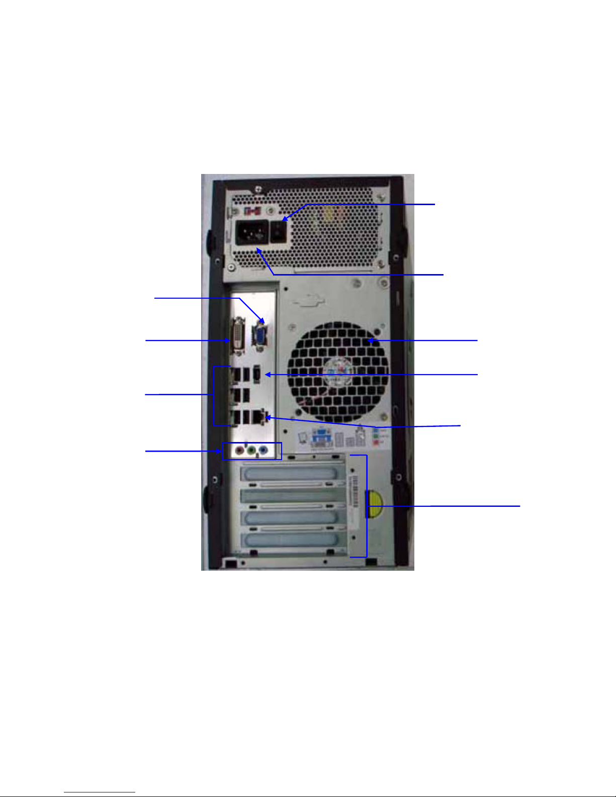
1.4 System's rear panel
(A)
Power ON/OFF
Switch
(B)
Power
Port
(I)
VGA Port
(E)
Expansion Slots
(C)
Fan Cage
(F)
Audio Ports
(D)
IEEE 1394a
p
or
t
(D)
Ethernet Port
(H)
DVI Port
(G)
USB Ports
7

2. Your System's Motherboard
2.1 Motherboard layout
Your computer's motherboard is the fundamental component. You will notice that
almost every component is connected to the motherboard through some port. Below is
an illustrative diagram for the motherboard included in your computer system.
Image courtesy for Intel® Corporation
8

Label Description
A Front panel audio header
B Speaker
C PCI bus connector
D PCI Express x1 connector 2
E Battery
F PCI Express x1 connector 1
G PCI Express x16 connector
H Rear chassis fan header (3-pin)
I Back panel connectors
J 12 V processor core voltage connector (2 x 2 pin)
K Processor socket
L Processor fan header (4-pin)
M Serial header
N Main power connector (2 x 12 pin)
O DDR2 DIMM 0 sockets
P DDR2 DIMM 1 sockets
Q Front panel header
R Alternate front panel power LED header
S Chassis intrusion header
T BIOS configuration jumper block
U Front chassis fan header (3-pin)
V Serial ATA connectors
W External SATA (eSATA) connector
X High-speed USB 2.0 header 2
Y High-speed USB 2.0 header 3
Z High-speed USB 2.0 header 1
AA IDE connector
BB IEEE 1394a header
CC High Definition Audio Link header
9
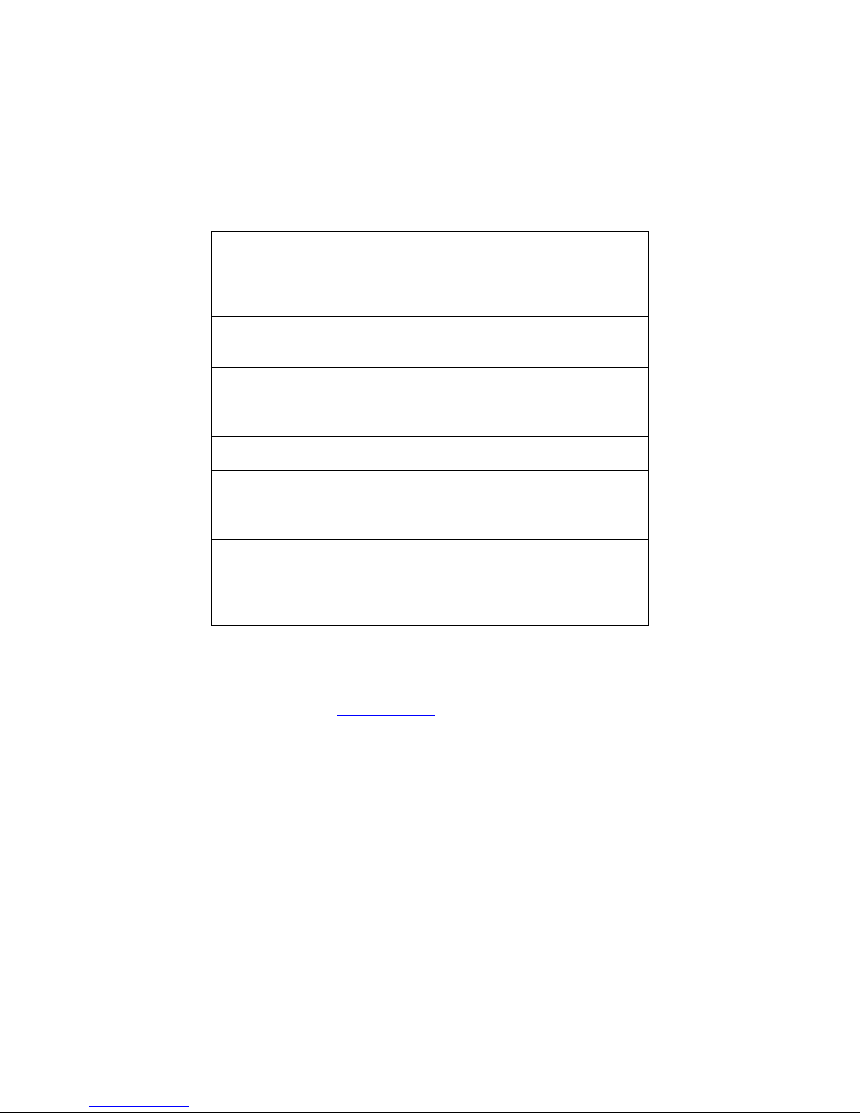
3. BIOS settings
The BIOS Setup program can be used to view and change the BIOS settings for the
computer. The BIOS Setup program is accessed by pressing the <F2> key after the
Power-On Self-Test (POST) memory test begins and before the operating system boot
begins. The following menus are available:
Menu Item Purpose
Maintenance Clears passwords and displays processor
information. The maintenance menu is displayed
only when the Desktop Board is in configure mode.
Manageability Configure options associated with Intel® Platform
Administration Technology.
Main Displays processor and memory configuration.
Advanced Configures advanced features available through the
chipset.
Security Sets passwords and security features.
Power Configures power management features and power
supply controls.
Boot Selects boot options.
Intel® ME Configures options for the Intel® Management
Engine and Intel® Active Management Technology.
Exit Saves or discards changes to Setup program
options.
For more information about the BIOS settings configuration we recommend
consulting Intel's® website (www.intel.com).
10
Table of contents
Other SAMsync Desktop manuals


