SAMUEL JACKSON 81667 User manual

81667 BALE NUMBER SCANNER
To install a Samuel Jackson Bale Number
Scanner, follow the steps below.
Mount the bale scanner near the bale conveyer on the side that the bale tag will be
affixed. Be sure that the face of the scanner is not more than 15 inches away from the
bale. However, you need to be sure that the scanner is far enough away that the pattern
can span the width of the barcode.
SETUP GUIDE
81667 BALE NUMBER BARCODE
SCANNER
81663 UNIVERSAL PRINTER

Page 2 of 11
LAST UPDATE: SEP-7-2018COPYRIGHT © SAMUEL JACKSON, INCORPORATED 2006
ALL RIGHTS RESERVED
If you have a Vomax microwave bale moisture
sensor, an arm is provided that can be used to
mount the barcode scanner to the Vomax stand at
an appropriate distance. A mounting plate for the
PLC box is also provided so that the Bale Scanner
PLC box can be mounted to the receiver stand of
the Vomax. The scanner cable provided is long
enough to mount the barcode scanner on either
side of the stand.
Run the scanner cable from the scanner
PLC box to the barcode scanner. Plug
the cable into the barcode scanner. The
scanner cable should be pre-wired to the
wiring blocks in the PLC box.
Disconnecting these wires may make
installation easier.
The correct wiring is given on the
barcode scanner wiring diagram at the
back of this guide. The cable should be
run through the covered channel on the
Vomax stand if the scanner is mounted
on the transmitter side of the Vomax.
You should make sure that the colored
wires from the cable and their respective numbered blocks match the wiring diagram in
the back of this guide.
Next, run a CAT5 cable from the ethernet port on
the bale tag scanner PLC to the network switch (SJI
part no. 21231) and plug it into an open port on the
network switch. Note that the cable should not
exceed 300 feet in length. If this network switch is
added, it requires 24VDC power.

Page 3 of 11
LAST UPDATE: SEP-7-2018COPYRIGHT © SAMUEL JACKSON, INCORPORATED 2006
ALL RIGHTS RESERVED
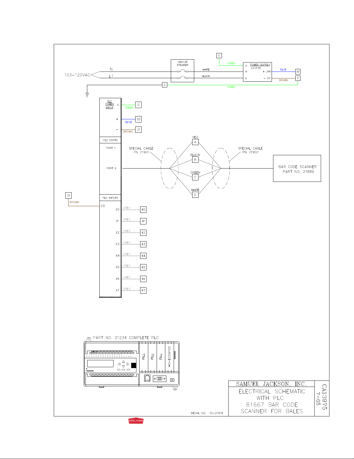
Apply 115 60/50 Hz AC power to the bottom of the circuit breaker in the bottom left
corner of the PLC box and turn on the circuit breaker in the PLC box. Refer to the
hookup flowchart in this guide for a basic view of the various connections.
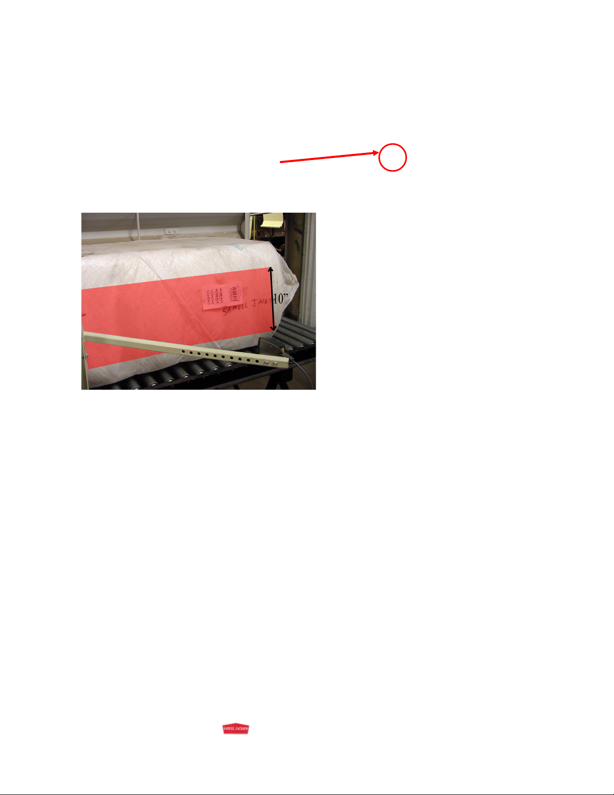
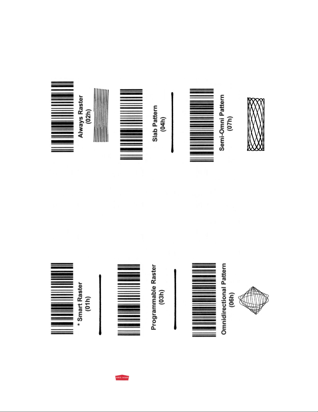
It is recommended that you set the
Scanner pattern to either “Smart Raster”
or “Omnidirectional Pattern” since these
two have shown to be the most reliable.
Most gins use Smart Raster, but if the
bale tags are not put on the same way
each time, you may want to switch to
Omnidirectional. To do this, simply scan
the corresponding barcode on the last
page of this manual. Using either of
these patterns with the scanner at the
recommended 15 inches away from the
bale, there is a 10-inch wide area on the
bale where the bale tag can be placed.
81663 UNIVERSAL PRINTER
Mount the Printer PLC box near the printer location.
Locate the cable that comes out of the printer PLC box and connect it to the printer. It
should already be wired to the terminals inside the PLC box. In some cases, it is easier to
run the cable if you disconnect the cable inside the PLC box. When reconnecting the
wiring, check to see that the wire colors match the numbers given on the printer wiring
diagram. Plug the cable into the printer.
Before loading the paper, take the top cover off of the printer and remove the plastic
piece that is restraining the print head. Load paper into the printer from the bottom or
back. Turn the knob on the side of the printer to feed paper through and check the paper’s
alignment. Be sure that the paper goes between the roller and the movable paper guide.
Apply 120 60/50 Hz to the bottom of the circuit breaker in the bottom left corner of the
printer PLC box the same way as the scanner PLC box.
Plug in and turn on the printer, then turn on the circuit breaker to the PLC. If done
correctly, the printer should print a header that looks like this:
115 60/50 Hz AC

Page 4 of 11
LAST UPDATE: SEP-7-2018COPYRIGHT © SAMUEL JACKSON, INCORPORATED 2006
ALL RIGHTS RESERVED
Run a CAT5 cable from the ethernet port on the printer PLC to the network switch (SJI
part no. 21231) and plug it into an open port on the network switch. Note that the cable
should not exceed 300 feet in length.
You need to set how long the printer waits to print after the bar code is scanned by
attaching a jumper wire from block 30 to the block corresponding to the desired interval.
This setting is necessary so that the information printed is accurate. The printer should
not print until after the Vomax has finished scanning the bale. See the wiring diagram in
this guide for more information on interval selection. The factory preset is 5 seconds.
If you have a Moisture Mirror II, you can control how often the printer prints
informational averages. Run CAT5 cable from the network switch in the PLC box to an
open port on the network switch in the Moisture Mirror PLC box (300 feet maximum).
To adjust Moisture Mirror II printer settings:
Press “SETUP” on the home screen of the Moisture Mirror II
Press “PRINTER SETUP” on the bottom-left.
Use this screen to set your printer to the desired settings

Page 5 of 11
LAST UPDATE: SEP-7-2018COPYRIGHT © SAMUEL JACKSON, INCORPORATED 2006
ALL RIGHTS RESERVED

Page 6 of 11
LAST UPDATE: SEP-7-2018COPYRIGHT © SAMUEL JACKSON, INCORPORATED 2006
ALL RIGHTS RESERVED
Direct
LOGIC06
Koyo ESC MENU ENT
N.C. N.C.C0 Y1 Y3 Y4 Y6 C2 Y16Y14Y13Y11
N.C. Y0 Y2 C1 Y5 Y7 Y17Y15Y10 Y12 C3GLG
N.C.C1 X5 X7 X1 0 X12 C3 X22X20X17X15X0 X2
N.C.
X4 X6 C2 X11 X1 3 X14 X23X2 1
C4
X16X1 X3
C0
PORT1 PORT2 RUN STOP
TERM
PWR
RUN
CPU
TX1
RX1
TX2
RX2
0 1 2 3 4 5 6 7 10 11 12 13 14 15 16 17 20 21 22 23
D0-06DR-D
Y
X

Page 7 of 11
LAST UPDATE: SEP-7-2018COPYRIGHT © SAMUEL JACKSON, INCORPORATED 2006
ALL RIGHTS RESERVED

Page 8 of 11
LAST UPDATE: SEP-7-2018COPYRIGHT © SAMUEL JACKSON, INCORPORATED 2006
ALL RIGHTS RESERVED
VS800 BARCODE SCANNER PATTERNS

Page 9 of 11
LAST UPDATE: SEP-7-2018COPYRIGHT © SAMUEL JACKSON, INCORPORATED 2006
ALL RIGHTS RESERVED
When performing a fresh setup of a DS475 Scanner, scan all of the following barcodes left to right and top
to bottom.

Page 10 of 11
LAST UPDATE: SEP-7-2018COPYRIGHT © SAMUEL JACKSON, INCORPORATED 2006
ALL RIGHTS RESERVED
IMPORTANT!
The following notice affects your warranty.
Electrical Controls and Your Safety
Your new Sam Jackson product may be equipped with electrical controls, or designed to interact with
controls on a related Sam Jackson product.
In the event that local, state, federal or other specified safety compliance is required, we will consider
modifications to meet the particular requirements. Implementation of alternative safety devices may incur
additional charges. No warranty of compliance with a particular standard is made in the absence of specific
reference to it in our quotation.
If you modify, or permit others to modify, these controls without specific written permission from Sam
Jackson, Inc. the warranty on your product will be void and there is a possibility of serious damage to
machinery, damage to product, serious injury to personnel, or death. The modifier of the controls assumes
all liability for these consequences.
Samuel Jackson, Incorporated
3900 Upland Avenue
Lubbock, Texas 79407
806-795-5218

This page intentionally blank
This manual suits for next models
1