Samyung ENC SMR-3600 User manual

======================================================================
======================================================================
SMR-3600
1
Chapter 1. Introduction of Radar.......................................................................................4
1. Introduction ...............................................................................................................4
1-1. Usage of manual .............................................................................................4
2. Composition ..............................................................................................................4
2-1. General............................................................................................................4
3. Specification ..............................................................................................................5
3-1. General............................................................................................................5
3-2. Transceiver......................................................................................................6
3-3. Monitor ............................................................................................................6
3-4. Connection Cable............................................................................................7
Chapter 2. How to operate...................................................................................................8
1. Introduction ...............................................................................................................8
2. How to use the front button and volume ...................................................................8
2-1. How to use direction button.............................................................................8
2-2. How to use the dedicate button.......................................................................8
2-3. Volume adjustment..........................................................................................9
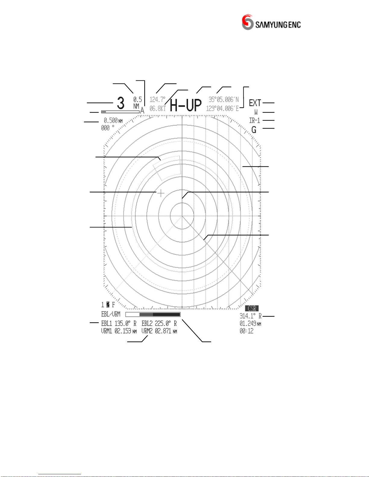
2-4. Screen Description ........................................................................................10
3. Turn ON/OFF .......................................................................................................... 11
3-1. Turn ON......................................................................................................... 11
3-2. Turn OFF ....................................................................................................... 11
3-3. Using time in total.......................................................................................... 11
3-4. How to control power during repair/maintenance .......................................... 11
4. How to use menu ....................................................................................................12
4-1. Screen display...............................................................................................12
4-2. Bearing.................................................................................................................16
4-3. EBL/CSR Read out (Display bearing line/cursor)..........................................17
4-4. Magenetic Var................................................................................................18
4-5. Distance Unit .................................................................................................19
4-6. Wake Point ....................................................................................................20
4-7. Waypoint........................................................................................................21
4-8. Tuning Mode..................................................................................................22
4-9. Timed TX .......................................................................................................23
4-10. TX Period.....................................................................................................24
4-11. Stand-by Time..............................................................................................25
4-12. Alarm Level..................................................................................................26
4-13. TX Pulse ......................................................................................................27
4-14. Target Mag. ........................................................................................................28
4-15. Color Set .....................................................................................................29
4-16. Language Set ..............................................................................................30

======================================================================
======================================================================
SMR-3600
2
4-17. Simulation....................................................................................................31
4-18. Outside Color...............................................................................................32
4-19. Inside Color .................................................................................................33
4-20. Bearing Adjust .............................................................................................35
4-21. Display Timing .............................................................................................36
4-22. Tune Set ......................................................................................................37
4-23. TURN-R Set ................................................................................................38
4-24. Error Set ......................................................................................................39
4-25. TX-Time.......................................................................................................40
4-26. GAIN-L Setup ..............................................................................................41
4-27. STC-H Setup ...............................................................................................42
4-28. Program Load..............................................................................................42
Chapter 3. How to operate.................................................................................................43
1.Control of display screen..........................................................................................43
1-1.Control of distance range ...............................................................................43
1-2. Elemination of heading line ...........................................................................43
1-3. Gain control ...................................................................................................43
1-4. Radar Interference Removal .........................................................................44
1-5. Snow, rain and interference removal .............................................................44
1-6. Removal of Sea Level Wave .........................................................................44
1-7. How to measure distance & bearing to target ...............................................45
1-8. How to use VRM (Variable Range Maker).....................................................46
1-9. How to use EBL (Electronic Bearing Line) ....................................................46
1-10. How to F EBL/VRM .....................................................................................46
1-11. How to measure distance and bearing by cursor ........................................46
1-12. How to move the center position on the screen ..........................................47
2. How to operate SAMYUNG radar ...........................................................................48
2-1. A fixed target on PPI screen ..........................................................................48
2-2. In monitoring any move of other ships (targets). ...........................................48
3. Other convenient functions .....................................................................................49
3-1. To display the own ship speed in the indicator ..............................................49
3-2. To display the heading in the indicator ..........................................................49
4. How to connect to external navigation equipment ..................................................49
5. Basic knowledge in observation..............................................................................50
5-1. Scanning range and target ............................................................................50
5-2. Navigational reflection wave..........................................................................51
Chapter 4. Installation........................................................................................................52
1. Summary.................................................................................................................52
2. Transmitter / Receiver set up ..................................................................................52

======================================================================
======================================================================
SMR-3600
3
2-1. Select of set-up location ................................................................................52
2-2. How to set-up ................................................................................................52
2-3. Inside wire connection...................................................................................54
3. Installation for instruction-equipment ......................................................................55
3-1. Installation point select ..................................................................................55
3-2. How to set up ................................................................................................55
3-3 power cable connect ......................................................................................55
4. Installation check.....................................................................................................55
4-1. Operation check ............................................................................................55
4-2. All sorts of adjustment ...................................................................................55
4-3. Packing list ....................................................................................................56
Chapter 5. Maintenance ....................................................................................................57
1. General ...................................................................................................................57
1-1. Cleaning ........................................................................................................57
1-2. Check out the tightness of screw, bolt...........................................................57
1-3. Check the cabling..........................................................................................57
2. Transceiver..............................................................................................................57
2-1. Radar Dome ..................................................................................................57
2-2. Bracket ..........................................................................................................58
3. Monitor ....................................................................................................................58
3-1. Cleaning of a Monitor LCD Screen................................................................58
Chapter 6. Installation drawing and circuit diagram...........................................................59

12 32


======================================================================
======================================================================
SMR-3600
6
3-2. Transceiver
•Diemension
1) Dia : 590mm
2) Height : 290mm
•Weight : 10Kg
•Plane of polarization : Horizontarget polarized wave
•Polar pattern
1) Horizontal Beam Width : 4.0°
2) Vertical Beam Width : 25°
3) Sidelobe Level : Below -21dB
•Revolution : Approx. 24r/min
•Tx Frequency : 9410±30MHZ
•Emission Type : P0N
•Peal Power : 4KW
•Transmission Bulb : Magnetron EEV MG5388
•Tx Pulse width/Repetition frequency
1) Pulse with set-up : Short
0.08 μsec/1640Hz - 0.125, 0.25, 0.5, 0.75,1.5NM RANGE
0.25 μsec/1160Hz - 3NM RANGE
0.5 μsec/580Hz - 6NM RANGE
1 μsec/580Hz - 12, 24, 36NM RANGE
2) Pulse with set-up : Long
0.08 μsec/1640Hz - 0.125, 0.25, 0.5, 0.75NM RANGE
0.25 μsec/1160Hz - 1.5NM RANGE
0.5 μsec/580Hz - 3NM RANGE
1 μsec/580Hz - 6, 12, 24, 36NM RANGE
3-3. Monitor
•Dimension
1) Width : 290mm
2) Height : 300mm
3) Depth : 142mm
•Construction : Desk Type
•Weight : 5.8kg
•Monitor Screen : 10.4” Colour TFT LCD
•Scale Zoom-in : Of 1 % of using RANGE or 70m, below whichever it is bigger
•VRM : .000 ~ 64.0 NM – Digital display
•EBL : .000° ~ 359° --- Digital display
•Synchonizing Method : Manual/Automatic switchable

======================================================================
======================================================================
SMR-3600
7
•Bearing scale : 1° scale, 360°
•Bearing display : Electronic type
•Operating point
•Front Panel button
1) Tune : Knob
2) Gain : Knob
3) Rain, Snow Clutter removal : Knob
4) Sea Clutter Removal : Knob
5) Guard : Switch
6) Distance Circle : Swich
7) Interference Rejection : Swich
8) Heading Line : Swich
9) Parallel Line : Swich
10) Center movement : Swich
11) 1 EBL/VRM : Swicth
12) 2 EBL/VRM : Swicth
13) F EBL/VRM : Swicth
14) Cursor : Swicth
15) Range ◀ : Swicth
15) Range ▶ : Swicth
16) ESC : Swicth
17) Menu : Swicth
18) Conversion : Swicth
19) Enter : Swicth
20) Center : Swicth
21) Direction button (8 direction) : Swicth
22) Brightness ▲: Swicth
23) Brightness ▼: Swicth
24) Power : Swicth
25) Transmit : Swicth
•Menu type : POP-UP Type
3-4. Connection Cable
•Antenna Cable Length : 15m
•Power Cable Length : 3m
•Data Cable Maximum Length : 3m

======================================================================
======================================================================
SMR-3600
8
Chapter 2. How to operate
1. Introduction
It offers to display a wide range of information in monitor by using control buttons.
•4 numbers dedicated volume
•8 directional button and center button for moving to center screen
•20 numbers of dedicated button.
•Wide range of choice for function in Menu
2. How to use the front button and volume
2-1. How to use direction button
•Moving cursor in Radar screen
•Selection of items in Menu
•To increase or decrease setting value
When pressed the direction button, cursor or selected bar is shifted to the same direction
as the display on the button. The longer pressing time is, the moving speed is increase.
2-2. How to use the dedicate button
These buttons have their endowed function as follows.
•
GUARD
: Set up desired monitoring area on screen and alarm function.
•
RING
: Display a concentric ceircle referring to measuring the distance.
•
IR
: Elimination of interference on Radar plotting
•
SHM
: Display of heading line
•
PLINE
: Display a parallel line with heading direction
•
OFF
CENT : To move Radar plotting to the center position
•EBL
VRM
1: Setting up and display NO.1 EBL and VRM
•EBL
VRM
2: Setting up and display NO.2 EBL and VRM
•EBL
VRM
F: Setting up and display flexile EBL and VRM

======================================================================
======================================================================
SMR-3600
9
•
CURSOR
: Display of cursor
•RANGE : Distance adjustment
•ESC : To return or move the previous screen in menu
•MENU : Call for Menu screen
•: To convert or alter the setting value
•ENT : Confirm the setting value or selection of menu
•BRILL : To adjust dimmer on screen and switch
•POWER : Function to turn ON/OFF
•TX : Function to ready for transmitting or changing the states of it
2-3. Volume adjustment
4 numbes dedicated volume has a function below and it can be adjusted in the night as
dimmer is in rear side.
•Tune : Adjust synchronized frequencies at receiver
•Gain : Adjust gain of receiving signal
•Snow, Rain Clutter elimination : Eliminating the reflected wave due to snow and
rain in a heavy weather
•Sea Clutter elimination : Eliminating the reflected wave due to sea surface.

======================================================================
======================================================================
SMR-3600
10
2-4. Screen Description
Parallel
line
Range
Dist. Between
Range Ring
Tuning
Bar
Dist./
Bearing
Between
P.Line
Heading Bearing
Speed Latitude Longitude
Heading Display
Extension
Waypoint
Interference
Rejection
Guard
Cursor
Bearing
Dist.
Time
1EBL/VRM
2EBL/VRM Screen Color
EBL
Heading LIne
Cursor
Guard
Zone
VRM
Auto Tuning
•Display on top of the screen regarding bearing, speed, latitude and longitude and set-up
on right bottom of the screen for destination is only available when the singanl from Gyro
Compass and GPS is nput to DATA port.

======================================================================
======================================================================
SMR-3600
11
3. Turn ON/OFF
3-1. Turn ON
1) Press POWER button.
2) I t will be ready after preheating time of 1’ 30” (90 seconds) is passed.
3) Press TX button and Radar starts transmitting.
3-2. Turn OFF
1) Press POWER button for 2-3 seconds.
2) Radar will be in state of stoppage and all functions stopped.
3-3. Using time in total
In the state of preheating, the time shown in screen (**** time) is the total time in using
Radar. It is determined to replace or maintain Magnetron referring to total time used.
3-4. How to control power during repair/maintenance
Even power is OFF, unt inside still exited especially in Monitor that cause eletric shock
while in repair or maintenance. Therefore you are requested to stop the power provided by
rectifer (in case of using rectifier), or separate power cable from the rear side of Monitor.

======================================================================
======================================================================
SMR-3600
12
4. How to use menu
4-1. Screen display
1) MENU ->[◀][▶] -> [FUNC/DISPLAY SET] -> [▲][▼] -> [HEADING MODE]
-> Press ENT button and then there will be a blue line on screen.
2) Select one of [H-UP, N-UP, C-UP] [◀][▶].
3) Press ESC button after ENT button for the return to screen.

======================================================================
======================================================================
SMR-3600
13
4-1-1. H-UP (Heading Up, Display the other’s bearing)
•Make the stem display on the screen (Bearing 0°).
•If stem’s bearing is changed, it changes the bearing of echo image on screen.
•Display the other’s bearing in case there’s no connected with Gyro Compass such as
the equipment that is able to get bearing information.
•Following display is for the screen that there’s GPS or Gyro Compass signal input
through data port.

======================================================================
======================================================================
SMR-3600
14
4-1-2. N-UP (Norse Up, True bearing display)
•The north displays as a true image on the screen.
•Even the vessel’s stem changed, the image range does not change.
•Need the equipment that is able to get bearing information such as Gyro Compass.
•Displays stem bearing, speed, longitude and latitude as an option.

======================================================================
======================================================================
SMR-3600
15
4-1-3. C-UP (Course Up)
•When press course-up switch for course setup, vessel’s bearing should be a true
imageon screen.
•Even the vessel’s stem is changed, the echo image bearing does not change and
vessel stem line is rotated as the change of vessel stem direction.
•It needs the equipment that is able to get bearing information such as Gyro Compass.
•Display vessel’s stem bearing, speed, longitude and latitude on screen as option
(Notice) It is available to display a data of Gyro Compass and GPS on the screen as
above and this is only available for the option.
The below shows a screen which is no data input.

======================================================================
======================================================================
SMR-3600
16
4-2. Bearing
1) MENU -> [◀][▶] -> [FUNC/DISPLAY SET] -> [▲][▼] -> [BEARING] -> Press
ENT button and then there’s a blue line on [BEARING].
2) Select true bearing or magenetic bearing by using [◀][▶] button.
3) Press ENT button and ESC button for the return to screen.
•It needs the equipment that is able to get bearing information such as Gyro Compass.

======================================================================
======================================================================
SMR-3600
17
4-3. EBL/CSR Read out (Display bearing line/cursor)
1) MENU -> [◀][▶] -> [FUNC/DISPLAY SET] -> [▲][▼] -> [EBL/CSR READ OUT]
-> Press ENT and then there’s a blue line on [EBL/CSR READ OUT].
2) Select the others or true north] by [◀][▶].
3) Press ENT and ESC for the return to screen.
•It needs the equipment that is able to get bearing information such as Gyro Compass.

======================================================================
======================================================================
SMR-3600
18
4-4. Magenetic Var.
1) MENU -> [◀][▶] -> [FUNC/DISPLAY SET] -> [▲][▼] -> [MAGNETIC VAR.]
-> Press ENT and there’s a blue line on [MAGNETIC VAR.].
2) Select [Auto, Manual, +00.0°] by [◀][▶] and press ENT.
Auto : Display a true bearing on External input GPS DATA.
Manual : Display a bearing with adding bearing correctiong value to a true bearing
on External input GPS DATA.
+00.0°: Bearing bearing correction, Input the wanted correction value(-99.9°~ +99.9°).
3) Press ENT and ESC for the return to screen.
•It needs the equipment that is able to get bearing information such as Gyro Compass.

======================================================================
======================================================================
SMR-3600
19
4-5. Distance Unit
1) MENU -> [◀][▶] -> [FUNC/DISPLAY SET] -> [▲][▼] -> [DISTANCE UNIT]
-> Press ENT and then there’s a blue line on [DISTANCE UNIT].
2) Select [NM, KM] by using [◀][▶] button.
NM : Display a distance as Mile.
KM : Display a distance as Km.
3) Press ENT and ESC for the return to screen.

======================================================================
======================================================================
SMR-3600
20
4-6. Wake Point
•Display a trace that is passed a target.
1) MENU -> [◀][▶] -> [Func/DISPLAY SET] -> [▲][▼] -> [WAKES] -> Press ESC and
then there will be a blue line on [WAKES].
2) Select [Off, Short, Long] by using [◀][▶] button.
Off : No display a target trace.
Short : Display a target trace shortly.
Long : Display a target trace long.
3) Press ENT and ESC button for the return to screen.
Table of contents
Popular Radar manuals by other brands

Bosch
Bosch FR5CPCCF manual

Velleman
Velleman High-Q Velleman-Kit K3502 Illustrated assembly manual

Furuno
Furuno DRS6A X-Class installation manual

Sensors & Software
Sensors & Software pulseEKKO product manual

Endress+Hauser
Endress+Hauser Micropilot FMR51 Brief operating instructions

BENDIX
BENDIX VORAD VS-500 Operator's manual