Samyung SUPERTRACK SDA-390 User manual

INSTALLATION AND OPERATION MANUAL
FOR SUPERTRACK MODEL SDA-390
Ku-BAND TV-RO ANTENNAS
SAMYUNG ENC.
Tel)+82-42-932-0351~2
Fax)+82-42-932-0353
Web) http:///
www.samyungenc.com
28.03. 2011

i
SAMYUNG ENC SuperTrack systems are manufactured
in the Republic of South Korea.
Copyright Notice
All Rights Reserved. The information contained in this document is proprietary to
SAMYUNG ENC. This document may not be reproduced or distributed in any form
without the consent of SAMYUNG ENC. The information in this document is
subject to change without notice.
Copyright 2011 SAMYUNG ENC.

ii
Revision History
Revision
Date Description By Remarks
1.0 14. 01. 2011 Initial Release(PCU Ver. K1.000 &
ACU Ver. 1.00) Hong
1.1 28. 03. 2011 PCU version is updated(PCU Ver.
K1.040 & ACU Ver. 1.00) Hong
1.2 16. 06. 2011 Change the photo of packing
box(PCU Ver. K1.050 & ACU Ver.
1.10)
Hong

a
Contents
1.
Introduction.........................................................................1
1.1.
Purpose ....................................................................................... 1
2.
Installation...........................................................................2
2.1.
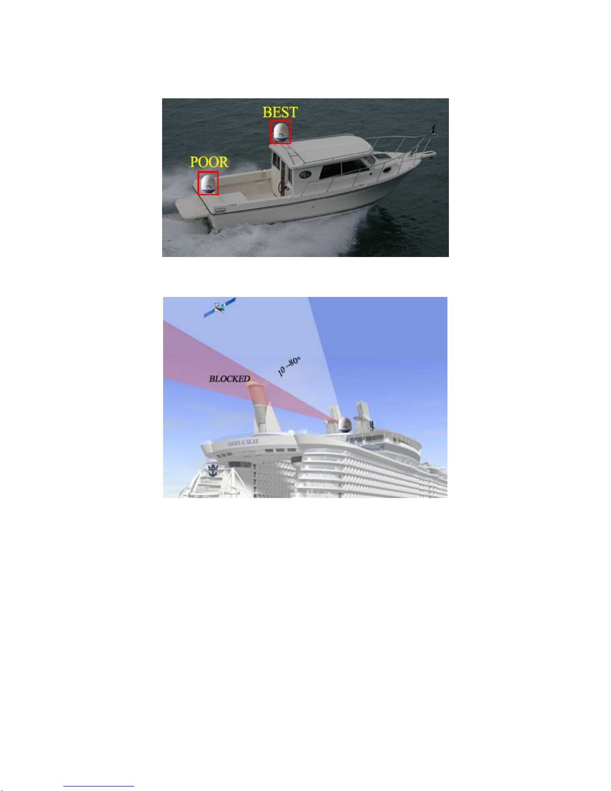
Site Selection .............................................................................. 2
2.2.
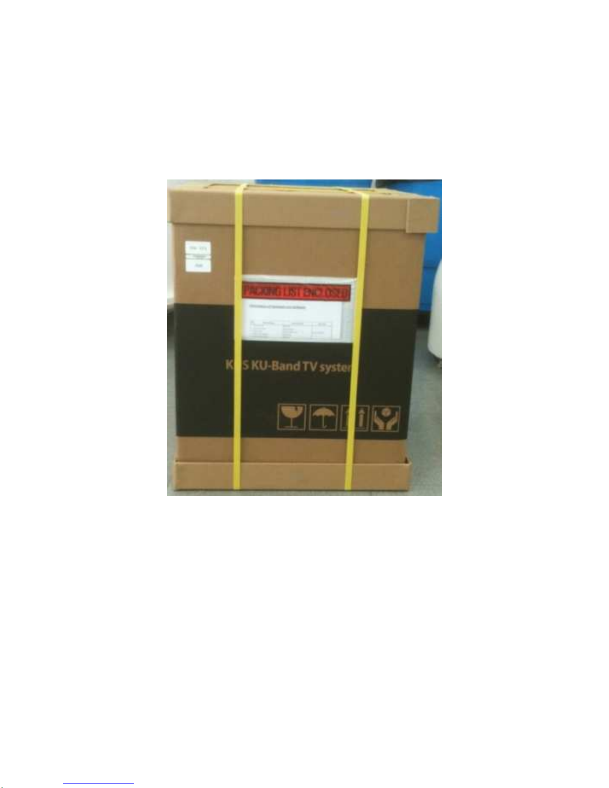
Unpacking the Unit ..................................................................... 4
2.3.
Equipment and Cable Installation .............................................. 5
2.4.
Antenna Unit Mounting............................................................... 6
2.5.
ACU Mounting............................................................................. 9
2.6.
Gyro Connection(Optional)....................................................... 10
2.7.
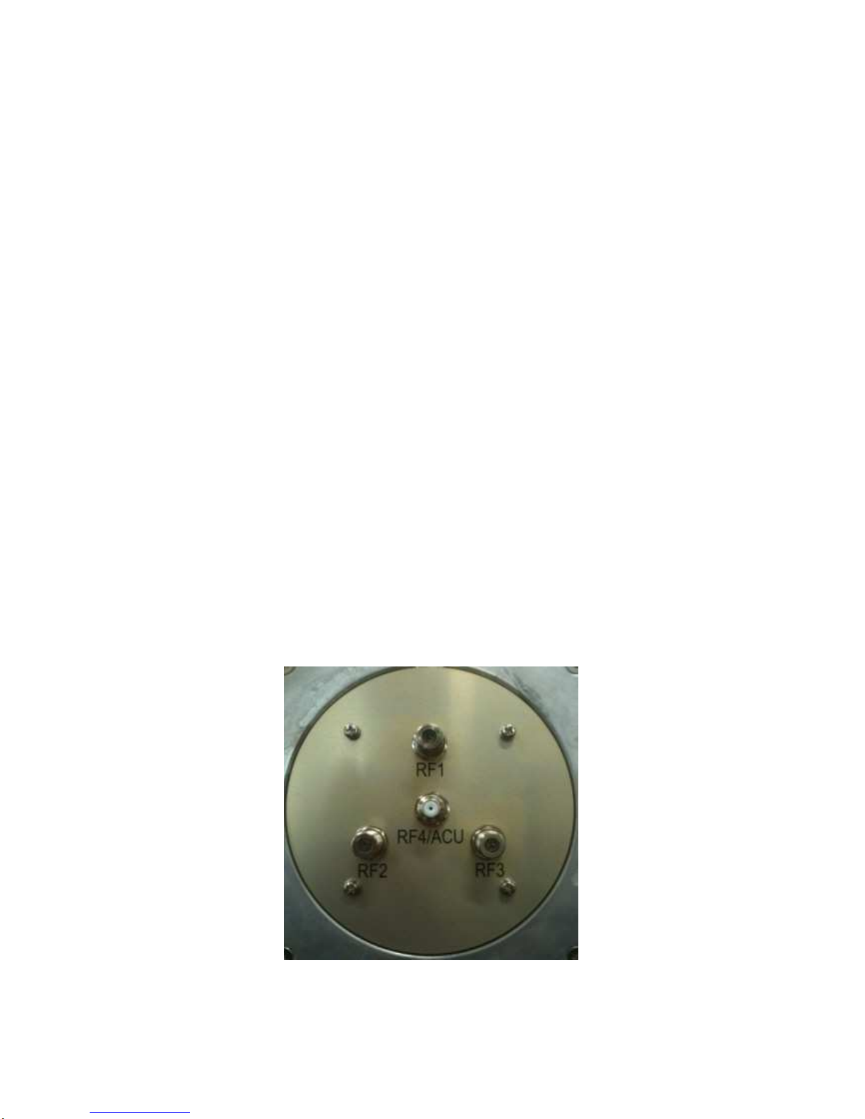
Cable Connection...................................................................... 13
3.
Operation...........................................................................16
3.1.
Front Panel Functions .............................................................. 16
3.2.
ACU Display Operation............................................................. 19
3.3.
Set-up Mode .............................................................................. 22
4.
How to Operate SCS..........................................................31
4.1.
Connect to PC ........................................................................... 31
4.2.
Setting the parameters of the satellite..................................... 33
4.3.
Skew Control............................................................................. 40
4.4.
Antenna State............................................................................ 42
4.5.
Installer...................................................................................... 45
Appendix A: Example of Setting the Satellite’s Parameters
Using SCS...............................................................................50
Appendix B: Error Code Definition........................................55
Appendix C: Specifications....................................................59
Appendix D: Satellite Information..........................................60
Appendix E: Radome and Antenna Mounting Holes Layout.64

1
1. Introduction
1.1.Purpose
The purpose of this manual is to provide the necessary information required by the
end user, customer and installer to successfully install the SDA-390 antenna and
controller and to program the KA-80 for operation.
It is recommended that all personnel responsible for operating SDA-390 systems
should know which type of system they have, read and understand the basic terms,
and be familiar with the operation of these systems.
Although installations may be completed by the customer’s preferred personnel, it is
also recommended that personnel be trained in the SAMYUNG ENC suite of
equipment installation procedures and trained by the relevant SAMYUNG ENC.
experts.

2
2. Installation
2.1.Site Selection
Determine the optimum mounting location for the antenna radome assembly. It
should be installed where:
1. The antenna has a clear line-of-sight view of as much of the sky as is practical.
Choose a location where masts or other structures do not block the satellite signal
from the dish as the boat turns.
2. The antenna is situated at least 5m away from other transmitting antennae (HF,
VHF and radar) that may generate signals that may interfere with the SuperTrack
SDA series antenna. The further away the SuperTrack SDA Series antenna is from
other such antennae, the less impact their operation will have on it.
The antenna radome assembly should be rigidly mounted on the boat. If necessary,
reinforce the mounting area to ensure that it does not flex due to the boat’s motion
or vibration.
Figure 2-1 Best Location I

3
Figure 2-2 Best Location II
Figure 2-3 Antenna Blockages

4
2.2. Unpacking the Unit
Cut the band and remove the items of antenna equipment. Do not turn the box on its
side to tip or roll out the product, or turn the box upside down to remove it.
Figure 2-4 Unpack the Antenna

5
2.3.Equipment and Cable Installation
The coax connector bracket beneath the radome is labeled. The functional
assignment of these labels is as follows:
SDA-390 Connectors
RF1: Connect to the multi-switch (Vertical Low).
RF2: Connect to the multi-switch (Horizontal Low).
RF3: Connect to the multi-switch (Vertical High).
RF4/ACU: Connect to the ACU.
NOTE
: Unused coax connections (on the connector bracket) MUST be terminated
with a 75ohm terminator.
NOTE
: We recommend the following cable types for cable lengths:
-within 20m: RG6
-within 50m: RG11
-within 100m: LMR400
-within 200m: LMR600
NOTE
: Impedance of cable is 75ohm. Also you can select the other cable types.
You have to keep in mind that we recommend all attenuation of cable is under
20dB at 2.5GHz.
Figure 2-5 RF Connector Bracket

6
2.4.Antenna Unit Mounting
Drill four bolt holes and cut out a cable access hole on the mounting site. (See
reference appendix.)
Position the base plate over the mounting holes and the cable access hole, and
then align the radome base plate’s “Bow” label (shown in Figure 2-6) with the
ship’s bow.
Figure 2-6 “BOW” Label of the Radome Base
1. Connect the data/power and the RF cables from below decks to the base plate
with a 7/16” wrench, applying 30 pounds of torque. Check the label on both ends
of each RF cable to match its antenna base-plate connector. Do NOT use Teflon
gel on the cable fittings as it reduces signal strength at high frequencies.
2. Install flat washers and spring washers and a mounting bolt to each mounting hole of
theradome basefrom the underside of the mounting surface. Apply Loctite 241 to the
threads of the mounting bolt up near the mounting surface and tighten each of the 4
bolts to 24 in-lb (21 kg-cm) of torque [finger tight, then about 1/4 turn tighter] with a
wrench. DO NOT OVER-TIGHTEN. You have to install mounting bolts of the proper
length. If a bolt is too long, the extra length of threaded rod that extends above the
radome base should be cut off.

7
Figure 2-7 Tighten the nuts from below

8
3.
Remove the screw and wire tie holding the Antenna.
Please refer to Figures 2-8
below.
Figure 2-8 Fixed the Forms and Wire Ties

9
2.5.ACU Mounting
The ACU may be mounted either horizontally or vertically.
1. The ACU should be placed in a dry location that is convenient for the user.
2. It must be situated in a place that is not susceptible to magnetic interference; nor
must it be situated on a level surface.
3. It should be placed so that the LCD display is visible and the buttons are easily
accessible.
Figure 2-9 KA-80 ACU

10
2.6.Gyro Connection(Optional)
The SuperTrack SDA-390 accepts NMEA-type gyro via NMEA port of the ACU
back panel. Connect the NMEA port with a ship’s gyro using a 9-pin connector
(female type).
Figure 2-10 NMEA Connector
Figure 2-11 Female-type 9-pin Connector

11
Gyro Cable Connection
The cable connection differs according to the type of NMEA. Connect the NMEA
port with the ship’s gyro, as indicated in Figures 2-12 and 2-13 below.
Pin No. Pin Name
1 RX-
2 RX+
3 TXD
4 Dummy
5 GND
6 Dummy
7 Dummy
8 Dummy
9 Dummy
Table 2-1 Using the pin number of the ACU Connector for the NMEA type
Figure 2-12 Cable Connection NMEA 422/485
Figure 2-13 Cable Connection NMEA 232

12
NOTE
: KA-80 ACU can accept the various format of NMEA, as follow: HDT; HDG;
HDM.
NOTE
: SuperTrack SDA-390 will be initializing when NMEA signal is accepted via
NMEA. Installer doesn’t need any setting on the ACU and antenna when connects
the NMEA signal.

13
2.7.Cable Connection
For the SuperTrack SDA-390 to work, you must connect the RF cables to your
satellite TV receiver(s). Each RF cable must be an RF (75 ohms) cable fitted with F-
type connectors. The RF cables should already be connected to the antenna base
plate. There should be one ~ four coax cables routed from the ACU to the Antenna
unit according to your configurations. Note that Data and Power are transmitted
through a single coax cable.
This cable should be connected to the RF4/ACU
labeled “RF connector of the antenna base plate” and the connector of the ACU
labeled “ANTENNA.”
The remaining coax cable routing depends on your
configuration. Due to the signal polarization of the satellites, it is possible for the
SuperTrack SDA-390 to support more than two satellite TV receivers aboard a boat.
To install more than two satellite TV receivers/TV pairs, an active multi-switch is
placed between the Antenna Unit and the Satellite TV receivers. The following
sections provide details for the installation of both a single satellite TV receiver and
multiple satellite TV receivers.
To connect the SuperTrack SDA-390 to your satellite TV receiver(s), choose one of
the following configurations (based on the number of satellite TV receivers you will
connect to the antenna):
Option 1 - Connecting one satellite TV receiver for one satellite
Option 2 - Connecting multi satellite TV receivers
Connecting one satellite TV receiver for one satellite (Only use the ‘HH’
polarity of the satellite)
One satellite TV receiver for one satellite is the simplest type of cable installation.
Only two coaxial cables should be connected between the antenna unit and the
satellite TV receiver, as shown in Figure 2-14. One end of the RF cable should already
be connected to the connector labeled “RF4” on the base of the SuperTrack SDA-390
antenna. Connect the other end of the RECEIVER cable to the satellite TV receiver
connector labeled “LNB,” “ANT/SAT,” or “satellite IN.” And, the “RF4/ACU” connector of
the antenna base plate must also be connected to the “ANTENNA” connector of the
ACU. In this configuration, every satellite should be selected manually using the ACU.
NOTE
: Before you connect an RF cable to a satellite TV receiver, turn on the satellite

14
TV receiver and TV and verify that there is no AC voltage on the satellite TV receiver’s
input connector, as measured between the center conductor and the shield. If AC
voltage is present on the connector, DO NOT connect the RF cable until you have
corrected the problem. This is a potentially dangerous condition that will damage the
antenna’s electronics.
Figure 2-14 One Satellite TV Receiver Installation
Connecting multi satellite TV receivers (Use of the all polarity of satellite)
In European systems that come with a Quattro LNB (optional Quad LNB), all four
RF outputs from the SuperTrack SDA-390 antenna should be connected to the
multi-switch. Connect each of the satellite TV receiver’s inputs to the output
connectors on the multi-switch. Connect the multi-switch unit in accordance with
the manufacturer’s instructions. Figure 2-15 shows an example of a European

15
multi-switch (4 inputs and 4 outputs) configuration.
RF1: Low Band Vertical
RF2: Low Band Horizontal
RF3: High Band Vertical
RF4: High Band Horizontal
RF1 RF2 RF3 RF4/
ACU
IRD #4IRD #3IRD #2
110~220VAC
50~60Hz
PC
Diagnostics
AN ENNA
Antenna Control Unit
(ACU)
RECEIVER
Vertical
/Low
Horizontal
/Low
Horizontal
/High
Vertical
/High
OU 1 OU 2 OU 3 OU 4
4X4
Multiswitch
RF RF RF RF
Master IRD
SA IN V
Figure 2-15 Four Satellites TV Receivers Installation with European LNB
NOTE: If you want use more satellite TV receivers than four, you can choose 8

16
outputs or 16 outputs.
3. Operation
3.1.Front Panel Functions
1
. MENU
button – Press the MENU button for more than 3 seconds to enter the
set-up mode. When you want to escape from the set-up mode, press MENU again
for more than 3 seconds. Another function of the MENU button is that of checking
the error message when the SDA-390 makes an error. When the error LED is on,
press the MENU button briefly. Then, you will be able to see the hexadecimal error
message. Please press the NEXT button for about 2 seconds to clear the error. If
you press MENU briefly again, you can go back to normal operation.
NOTE
: KA-80 ACU can display the error message as binary. Press the MENU
button and press NEXT button for 3 seconds. Then, you will be able to see the
binary error message.
NOTE
: Operator can make sure the communication status of ACU and antenna as
below when press MENU and press SEARCH shortly again. Packet means the
number of command from ACU, loss means the number of loss on the PCU. The
more loss this display, communication status is not good.
Figure 3- 1 Packet Loss
2.
SLEEP
button – Press the SLEEP button to enter the sleep mode when antenna
is tracking the satellite. The antenna does not conical scan when the TRACK
button is pressed. It function can reduce the noise of motor when vessel is
anchored at the dock or calm shore. This button is also used to scroll left (
◀
) in
the menu.
3.
NEXT
button – Press the NEXT button to select your preprogrammed next
satellite. When your desired satellite is displayed, stop pressing NEXT, and then,
after 3 seconds, the antenna automatically searches for your desired satellite.
Table of contents
Popular Antenna manuals by other brands

DirecTV
DirecTV TRKS26 installation manual

Intellian
Intellian v100NX Installation & Operation User Guide

Winegard
Winegard Sensar HV CC-25HV Installation & operation manual

CommScope
CommScope CMAX-OMF7-43-UWI53 Installation instruction

Mars
Mars MA-WA56-DP25N quick start guide

JMA Wireless
JMA Wireless SV02UTS136-PT installation guide

Spinner
Spinner BN A77150 installation guide

Antenna Experts
Antenna Experts AP-240030 installation manual

EchoStar
EchoStar DISH Pro Plus Twin LNBF installation instructions

EnGenius
EnGenius EnStation2 user manual

ETS-Lindgren
ETS-Lindgren 3110B manual

Andrew
Andrew ATC200-Lite Teletilt Installation and operation user guide