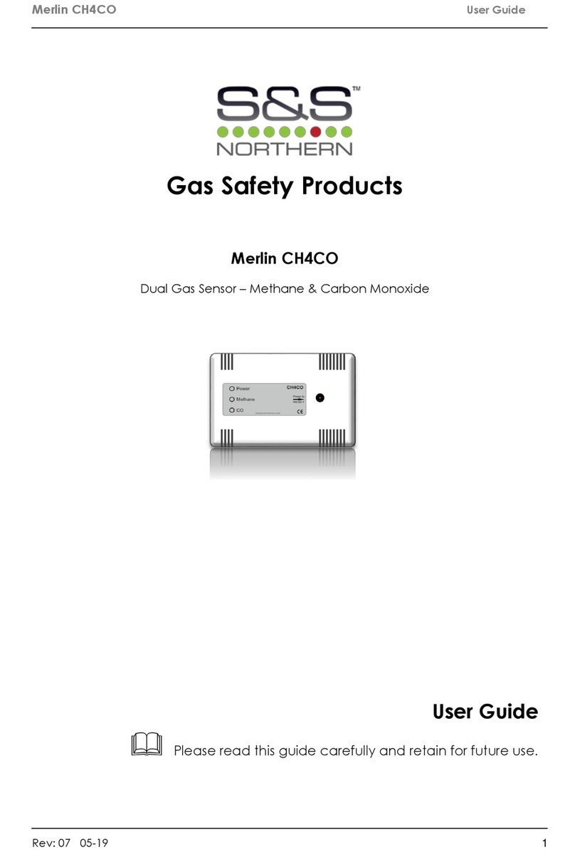
S&S Northern Merlin CO Detector User manual

Installation & Operation Manual Merlin Gas Detector
Rev: 18 03-20 1
Merlin Gas Detector
Installation & Operation Manual
Please read this manual carefully and retain for future use.
At S&S Northern, we supply a full range of remote gas detectors including carbon monoxide (CO), natural
gas (NG) and liquid petroleum gas (LPG) that are compatible with our range of Merlin control panels.
The information contained within this manual should be referenced for typical installation and operation
only. For specific requirements that may deviate from the information in this guide –contact your supplier.

Installation & Operation Manual Merlin Gas Detector
Rev: 18 03-20 2
Contents
INSTALLATION ...........................................................................................3
Planning........................................................................................................................... 3
Typical Location and Positioning................................................................................ 3
Fixing ................................................................................................................................ 4
Board Overview ............................................................................................................. 4
Wiring the Detector....................................................................................................... 5
Audible Alarm Switch ................................................................................................... 5
Testing the system.......................................................................................................... 5
Trouble Shooting ............................................................................................................ 6
Specification .................................................................................................................. 6
OPERATION ................................................................................................7
First Power Up ................................................................................................................. 7
Service & Maintenance ............................................................................................... 7
Bump Testing .................................................................................................................. 8
End of Life........................................................................................................................ 8
IMPORTANT WARNING STATEMENTS ...................................................11
Manufacturer’s Warranty........................................................................................... 11
Installation Details........................................................................................................ 12

Installation & Operation Manual Merlin Gas Detector
Rev: 18 03-20 3
INSTALLATION
Planning
Our detectors should be installed in areas at risk of gas leaks e.g. over boilers, valves or meters.
Take in to account the design of the air flow patterns within the zone area.
Detectors should be installed in the correct orientation, as recommended by the manufacturer,
and ease of access should be accounted for to allow for any bump tests, recalibration and
other forms of maintenance.
Areas to avoid
Avoid conditions of any other environmental factors that could potentially impede the
accuracy and operation of the detectors such as; condensation; vibration; temperature,
pressure, the presence of other gases, electromagnetic interference and draft zones.
Area of coverage
Consider the coverage required and function of the area. Emphasis should be placed on
airflow patterns and correct placement, not perceived detecting ranges. The target gas will
only be identified when contact is made with the sensing element itself.
Typical Location and Positioning
Locations for detectors will vary based on the intended application and target gas, they should
be located near identified sources of a potential gas leaks/ pockets where hazardous gas
could quickly accumulate and areas of identified consequential risk.
The composition of the target gas and its density relative to air are used as the basis for the
recommended height of sensors. Generally, the installation height of a sensor for a heavy gas
(such as propane) would be close to the lowest point in the area, and for a light gas (such as
methane) would be close to the highest point in the area.
These recommended heights may vary based on air flow and temperature conditions in
addition to the proposed application and location –this is particularly apparent with oxygen
depletion sensors, and the target gas that they are used for.
Target Gas
Typical Detector Position
Natural Gas/Methane (NG/CH4)
High Level - 300mm (1ft) from ceiling
Liquid Petroleum Gas (LPG)
Low Level - 300mm (1ft) from ground level
Carbon Monoxide (CO)
Breathing Zone - 1700mm (5ft 6”) from ground level
Hydrogen (H)
High Level - 300mm (1ft) from ceiling
Max number of detectors per zone is 3.
Multiple detectors may be required to adequately protect property and persons.

Installation & Operation Manual Merlin Gas Detector
Rev: 18 03-20 4
GDP2: Two zones / GDP4: Four zones / ‘S’ panel range: 1 Zone.
Fixing
Unpack all the parts!
1. Carefully remove the rear cover from the unit by unscrewing the hex screws located at the
bottom of the case. To do this –use the socket wrench provided.
2. Using the rear cover - mark the screw holes to the wall.
Ensure the wall surface is flat to prevent base distortion.
3. There is a pre-fractured area for cable entry provided on the inside of the rear cover which
may be cut away as required.
4. After executing the mounting and the connections –replace the rear cover ensuring the
two hex screws are re-installed and secured.
5. Make a note of the installation date on the label located on the side of the unit.
Board Overview
Be careful when creating access for cables –Damage to boards will void any warranty.
Do not attempt to remove the Circuit Board! This will void any warranty.

Installation & Operation Manual Merlin Gas Detector
Rev: 18 03-20 5
Wiring the Detector
Building Management Systems (BMS)
If you are connecting to Merlin ‘S’ range you will need to use [NC/COM] terminals as an alarm
relay. These are volt free connections to building management systems.
If you are using our ‘GDP’ range you will need to use the [C/L] terminal as an alarm relay.
A relay will change state when in alarm or when gas is detected.
BMS terminals can be used in conjunction with other external relays that affect other devices
and controls such as purge fans and audible alarms etc.
Audible Alarm Switch
There is a switch on the Detector circuit board.
The user can choose whether to have an audible alarm when dangerous gas levels are
detected. The alarm will continuously sound –there are no provisions to silence the alarm, gas
levels must drop to a safe value for the alarm to stop.
The buzzer measures approx. 65 dB from a distance of 300mm/1ft (tested in quiet conditions).
Testing the system
There is a [TEST] button on the Detector circuit board.
When the test button is pressed and held for 3 seconds –the detector will simulate an open
circuit to ensure alarms (low and then high), and other external devices connected operate as
intended in the event of a gas leak.
It is recommended testing your detectors with a calibrated gas. Contact your supplier.
This manual suits for next models
3
Table of contents
Other S&S Northern Accessories manuals


