S&S Northern Merlin PM2+ User manual

Merlin PM2+ User Guide
Rev: 2 05-19 1
Gas Safety Products
Merlin PM2+
Dual Current Monitor
User Guide
Please read this guide carefully and retain for future use.

Merlin PM2+ User Guide
Rev: 2 05-19 2
Table of contents
1General Information......................................................................................... 3
1.1 Panel Mounting ............................................................................................................3
2Circuit Board Terminals .................................................................................... 4
2.1 POWER ...........................................................................................................................4
2.2 FAN 1 & FAN 2 LIVE –Current monitoring ..................................................................4
3How to setup the current monitors ..................................................................5
3.1 Setting the minimum & maximum fan current..........................................................5
3.2 How to adjust the current monitor thresholds. ..........................................................5
4Specification .....................................................................................................6
5PM2+ Wiring Diagram....................................................................................... 7
6Manufacturer’s Warranty .................................................................................8

Merlin PM2+ User Guide
Rev: 2 05-19 3
1General Information
The Merlin PM2+ Current Monitor is a duel fan current monitor and is to be used in conjunction
with the Merlin systems: the unit can be used as an alternative to an air pressure differential
switch.
The PM2+ is designed for use with fans up to 18A running current (min 0.15A / 35W).
The PM2+ current monitor checks for a current running between the fan speed controller and
the fan and sends a signal to the Merlin gas interlock system dependant on whether or not the
fan is in operation.
It is recommended that the user reads this guide before using the system. Please do NOT
attempt to operate the unit until the contents of this document have been read and are
thoroughly understood.
1.1 Panel Mounting
The control panel is designed for surface mounting using 4 mounting screws. Removing the
cover on the panel gives access to the circuit board.
Important Warning Statements
Never ignore your device when in alarm.
This device requires a continual supply of electrical power –it will not work without power.
This device should not be used to substitute proper installation, use and/or maintenance of fuel burning
appliances including appropriate ventilation and exhaust systems.
Your product should reach you in perfect condition, if you suspect it is damaged, contact your supplier.
Information on waste disposal for consumers of electrical & electronic equipment. (EEE)
When this product has reached the end of its life it must be treated as Waste Electrical & Electronics
Equipment (WEEE). Any WEEE marked products must not be mixed with general household waste, but kept
separate for the treatment, recovery and recycling of the materials used.
Please contact your supplier or local authority for details of recycling schemes in your area.
Merlin PM2+ User Guide
Rev: 2 05-19 4
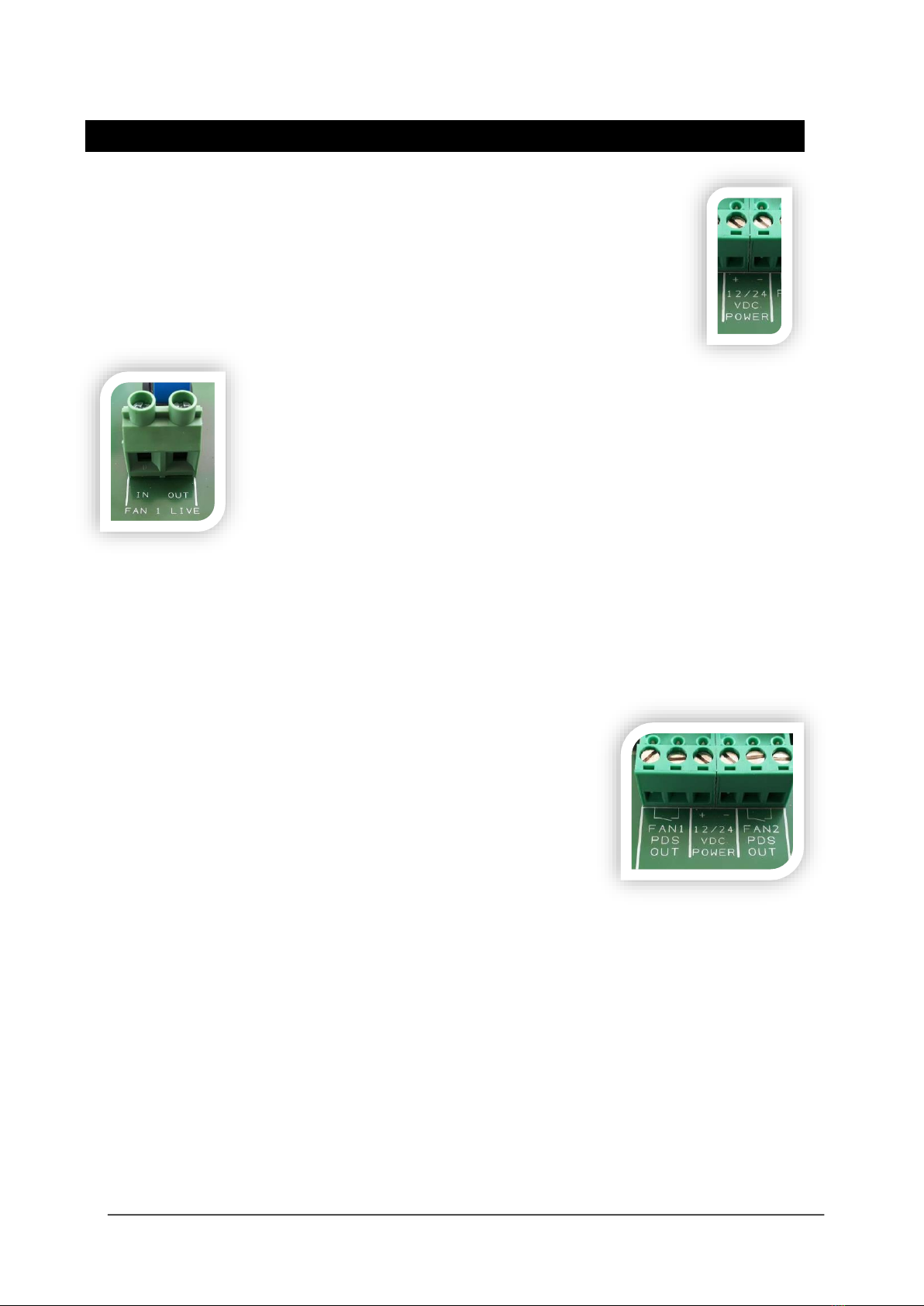
2Circuit Board Terminals
2.1 POWER
A 12v DC electrical supply should be supplied using the [+ - 12/24 VDC
Power].
2.2 FAN 1 & FAN 2 LIVE –Current monitoring
Located at the bottom of the main circuit board there are two
terminals for fan current monitoring, and these are marked up as [FAN
1 LIVE IN / OUT] & [FAN 2 LIVE IN / OUT].
The live feed from the fan speed controller should be taken through
these contacts. Each will monitor its own independent fan.
From a fan controller the live feed should be taken to the [IN] terminal
and the [OUT] terminal should wire to the fan motor.
Merlin panels 1500S / 2000S are sent from the factory with links in the terminals marked [SUPPLY
FAN PD SWITCHES & EXTRACT FAN PD SWITCHES] & [FAN1 PD SW & FAN2 PD SW]. If only one fan
is being monitored the relevant link should be taken out of the terminal connection.
These terminals are low volt only.
If both fans are being monitored –both links should be removed
and a connection should be supplied to the terminals marked on
the Merlin PM2+ panel [FAN PDS OUT].
There is an option to set a minimum and maximum running current for the fans to operate on. If
the current goes above the or below these parameters the PM2+ will switch relay for NC
(normally closed) to NO (normally open) for relevant [FAN# PDS OUT] and on the main Merlin
panel the relevant supply/ extract fans LED will begin to flash for ~10 seconds before the Fan
Fault alarm will be illuminated and the gas solenoid valve connected will be isolated.
For more information see section 3 –‘How to set up the current monitors’.
Merlin PM2+ User Guide
Rev: 2 05-19 5
3How to setup the current monitors
3.1 Setting the minimum & maximum fan current.
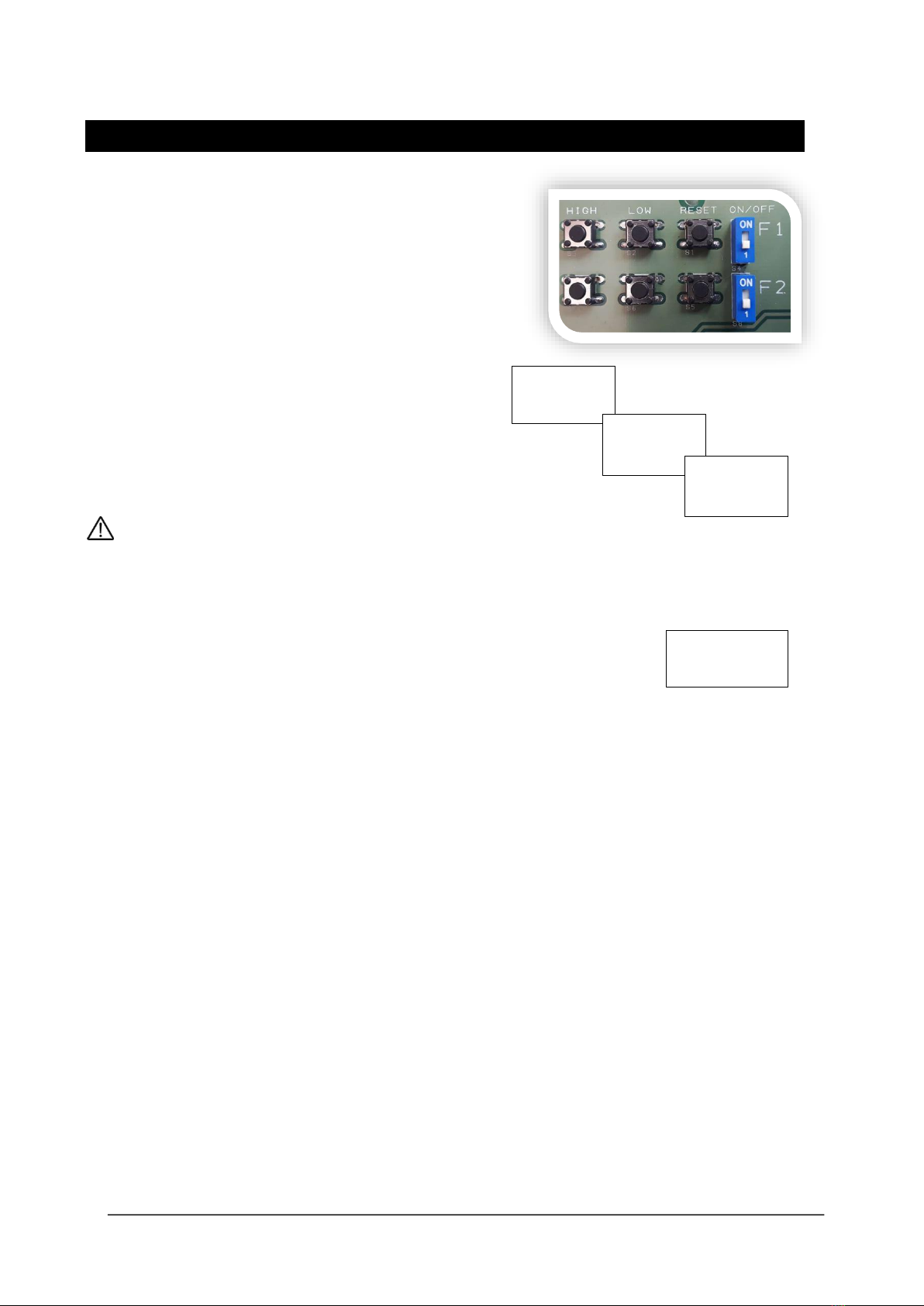
Turn Fan 1 (F1) switch to ON position.
The LCD screen will show Fan 1 current.
! - means Fan1 has not yet been calibrated.
Set Fan 1 minimum operating current.
Press and hold the F1 LOW button.
LCD screen will display: F1 LOW SAVED.
Set Fan 1 maximum operating current.
Press and hold the F1 HIGH button.
LCD screen will display: F1 HIGH SAVED.
Please repeat steps to set min & max current of Fan 2.
IF YOU ARE ONLY INTERLOCKING WITH ONE FAN, PLEASE LEAVE THE REMAINING [F] SWITCH
TO THE ‘1’ or ‘OFF’ POSITION TO PREVENT NUISANCE TRIPPING.
If the measured current falls below or rises above 10% of the permitted current, the LCD display
will show a ‘LOW!‘ or ‘HIGH!’ message next to the relevant fan and the gas solenoid valve
connected will be isolated. To adjust this threshold –see following section.
To erase the calibration data press and hold the relevant [RESET] button until ‘!’ appears.
3.2 How to adjust the current monitor thresholds.
The PM2+ has a factory set 10% dropout threshold for low and high values for both fans.
However, it is possible to alter between a 10% to a 40% dropout threshold if required.
Follow these instructions
1. Switch F1 and F2 switch OFF.
2. LCD will display ‘F1 and F2 OFF’
3. To change the LOW threshold, press and hold F1 and F2 LOW buttons together
4. The LCD screen will display ‘Offset L F1 10%’
5. Select different thresholds by pressing the F1 LOW button
6. After 5 seconds of inactivity the LCD screen will display the new low offset value for F1 (fan 1).
7. Once Fan 1 threshold has been set the LCD screen will prompt setting fan 2 ‘Offset L F2 10%’.
8. Repeat step 4, 5, 6 as above for Fan 2.
9. Once this has been setup the LCD screen will display the new low offset value for F2 (fan 2).
F1! 10.0A
F2 OFF
F1 LOW
SAVED
F1 HIGH
SAVED
F1 LOW!
F2 10.5A

Merlin PM2+ User Guide
Rev: 2 05-19 6
Repeat to adjust HIGH threshold as follows
10. To change the high threshold, press and hold F1 and F2 HIGH buttons together
11. The LCD screen will display ‘Offset H F1 10%’
12. Select different thresholds by pressing the F1 HIGH button
13. After 5 seconds of inactivity the LCD screen will display the new high offset value for F1 (fan 1).
14. Once Fan 1 threshold has been set the LCD screen will prompt setting fan 2 ‘Offset H F2 10%’.
Once you have completed setting the thresholds, switch F1 and F2 switches to ON.
You will now need to calibrate the fans, see section 3 ‘How to set up the current monitors’.
Fan Current HIGH Thresholds
Threshold Value
Max Fan Running Current
10%
-
18A
20%
-
16.5A
30%
-
15A
40%
-
14A
4Specification
Model:
-
PM2+
Power Supply:
-
12-24VDC
Current Consumption:
-
140mA @ 12vDC Max
Power Consumption:
-
~1.7W
Operating Temp Range:
-
10-40°C
Dimensions (mm):
-
W 190 x H 140 x D77
Net Weight (KG):
-
0.58
Certification:
-
CE / RoHS

Merlin PM2+ User Guide
Rev: 2 05-19 7
5PM2+ Wiring Diagram
1. FAN 1 IN / OUT MAX 18AMPS
2. FAN 1 NO/NC VOLT FREE OUTPUT to Merlin panel PD SWITCH terminal.
3. POWER IN 12-24 VDC
4. FAN 2 NO/NC VOLT FREE OUTPUT to Merlin panel PD SWITCH terminal.
5. FAN 2 IN / OUT MAX 18AMPS
6. Fan Current Monitor High Button
7. Fan Current Monitor Low Button
8. Fan Current Monitor Reset Button
9. Fan Current Monitor On/Off switches.

Merlin PM2+ User Guide
Rev: 2 05-19 8
6Manufacturer’s Warranty
3 Year Limited Warranty
Warranty coverage: The manufacturer warrants to the original consumer purchaser, that this product will be free of
defects in material and workmanship for a period of three (3) years from date of purchase. The manufacturer’s liability
hereunder is limited to replacement of the product with repaired product at the discretion of the manufacture. This
warranty is void if the product has been damaged by accident, unreasonable use, neglect, tampering or other causes
not arising from defects in material or workmanship. This warranty extends to the original consumer purchaser of the
product only.
Warranty disclaimers: Any implied warranties arising out of this sale, including but not limited to the implied warranties of
description, merchantability and intended operational purpose, are limited in duration to the above warranty period. In
no event shall the manufacturer be liable for loss of use of this product or for any indirect, special, incidental or
consequential damages, or costs, or expenses incurred by the consumer or any other user of this product, whether due
to a breach of contract, negligence, strict liability in tort or otherwise. The manufacturer shall have no liability for any
personal injury, property damage or any special, incidental, contingent or consequential damage of any kind resulting
from gas leakage, fire or explosion. This warranty does not affect your statutory rights.
Warranty Performance: During the above warranty period, your product will be replaced with a comparable product if
the defective product is returned together with proof of purchase date. The replacement product will be in warranty for
the remainder of the original warranty period or for six months –whichever is the greatest.
CONTACT US:
S&S Northern Head Office
Tel: +44(0) 1257 470 983
Fax: +44(0) 1257 471 937
www.snsnorthern.com
info@snsnorthern.com
South East Division
Tel: +44(0) 1702 291 725
Fax: +44(0) 1702 299 148
south@snsnorthern.com
S&S Northern is the owner of this document and reserves all rights of modification without prior notice.
Table of contents
Other S&S Northern Monitor manuals


