S&S Northern Merlin 3000S User manual

Merlin 3000S USER GUIDE
Rev: 07 05-19 1
Gas Safety Products
Merlin 3000S
Energy saving ventilation interlock and gas control system
User Guide
Please read this guide carefully and retain for future use.

Merlin 3000S USER GUIDE
Rev: 07 05-19 2
Contents
1About your new 3000S system ............................................................................................... 3
2System Positioning ................................................................................................................... 4
33000S Circuit Board ................................................................................................................. 4
POWER IN..................................................................................................................................................................5
GAS VALVE ...............................................................................................................................................................5
CONTACTOR ............................................................................................................................................................5
FAN CURRENT SENSOR - Extract Fan ....................................................................................................................5
FAN CURRENT SENSOR - Supply Fan.....................................................................................................................5
BMS OUT....................................................................................................................................................................5
FAN ENABLE - Extract Relay Output .....................................................................................................................5
FAN ENABLE –Supply Relay Output.....................................................................................................................5
PRESSURE SENSOR....................................................................................................................................................6
EM REMOTE...............................................................................................................................................................6
CO DETECTOR..........................................................................................................................................................6
CO2 Zone 1 - 0-10V Input ......................................................................................................................................6
CO2 Zone 2 - 0-10V Input ......................................................................................................................................6
CO2 MONITOR.........................................................................................................................................................7
GAS METER ...............................................................................................................................................................7
FIRE PANEL ................................................................................................................................................................7
12VDC OUT...............................................................................................................................................................7
OPTICAL SENSOR (ZONE 1) ....................................................................................................................................8
DUCT TEMP (ZONE 1)...............................................................................................................................................8
OPTICAL SENSOR (ZONE 2) ....................................................................................................................................8
DUCT TEMP (ZONE 2)...............................................................................................................................................8
0-10V OUTPUT –Extract Fan...................................................................................................................................9
0-10V OUTPUT –Supply Fan ...................................................................................................................................9
4System Start Up ........................................................................................................................ 9
System ON & OFF ....................................................................................................................................................9
Boost Button ...........................................................................................................................................................10
Adjusting the Screen Brightness..........................................................................................................................10
5Installation Settings ................................................................................................................ 11
SETTINGS 1 menu ...................................................................................................................................................11
SETTINGS 2 menu ...................................................................................................................................................11
SETTINGS 1 Explanation ........................................................................................................................................12
SETTINGS 2 Explanation ........................................................................................................................................13
6Warning Status ....................................................................................................................... 15
7Fault Status.............................................................................................................................. 16
83000S Wiring Spec ................................................................................................................. 18
9Manufacturer’s Warranty ...................................................................................................... 20

Merlin 3000S USER GUIDE
Rev: 07 05-19 3
1About your new 3000S system
The Merlin 3000S system is designed to vary the speed of ventilation based on multiple factors; 1)
Real-time gas usage via a turbine gas meter; 2) Carbon dioxide (CO2) detected levels in the area;
3) Smoke/ steam detection within a canopy and 4) Heat detection in the extraction ductwork.
For optimum results and protection-all system sensing elements should be utilised together but any
combination can be used.
The Merlin 3000S also carries out its duty as a traditional ventilation interlock and gas pressure
proving system alongside the ventilation-on-demand capabilities.
3000S Benefits
Interlock with ventilation using Fan Current Sensors or Air Pressure Differential switches
Optional gas proving function
Automates ventilation based on real-time gas consumption and CO2levels
Minimises heat loss via extraction by reducing fan speed when gas usage is minimal
Minimises heat loss via extraction by reducing fan speed when CO2levels are minimal
Pulsed output gas meter can be linked to other Building Management Systems
Reduced ventilation noise levels at times of low kitchen activity
Accepts Methane, LPG and CO detection systems
Covered by the S&S Northern 3 year warranty.
For more information and a range of gas safety systems, visit - www.snsnorthern.com
Important Warning Statements
Never ignore your device when in alarm.
This device requires a continual supply of electrical power –it will not work without power.
This device should not be used to substitute proper installation, use and/or maintenance of fuel burning
appliances including appropriate ventilation and exhaust systems.
Your product should reach you in perfect condition, if you suspect it is damaged, contact your supplier.
Information on waste disposal for consumers of electrical & electronic equipment. (EEE)
When this product has reached the end of its life it must be treated as Waste Electrical & Electronics Equipment (WEEE).
Any WEEE marked products must not be mixed with general household waste, but kept separate for the treatment, recovery and recycling of
the materials used. Please contact your supplier or local authority for details of recycling schemes in your area.

Merlin 3000S USER GUIDE
Rev: 07 05-19 4
2System Positioning
3000S Control
Panel
The control panel is designed for surface mounting using 4 mounting screws.
Removing the cover on the panel gives access to the circuit board (PCB).
Remove the PCB before drilling entry holes into the case.
CO2 Monitor
1-3m away from canopy
> 1m of a window and
1.7m from ground level.
CO Detector
1.7m from ground level.
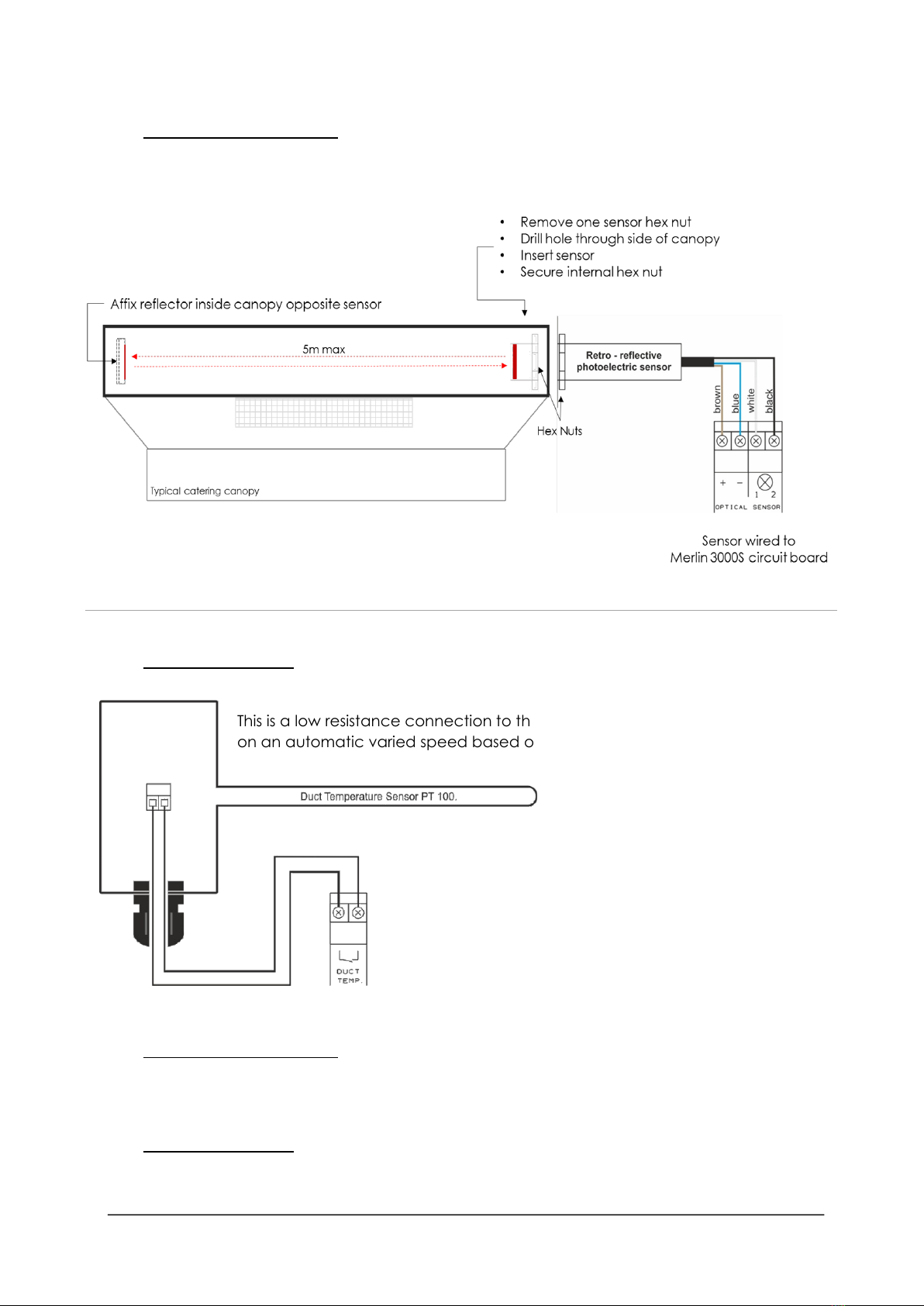
Optical Sensor
Fit inside of canopy.
Max 5m from infra-red reflector fitted opposite sensor.
Duct Temp
Sensor
Fit inside of ductwork where heat passes through.
Speed Controller
Recommended away from panel to avoid electrical noise.
33000S Circuit Board

Merlin 3000S USER GUIDE
Rev: 07 05-19 5
1. POWER IN
A 100-240VAC electrical supply should be supplied to the panel. This should be fused at 3A.
2. GAS VALVE
The gas solenoid valve should be powered using the terminal detailed [L N E GAS VALVE].
3. CONTACTOR
An electrical output will be supplied to an electrical contactor. This should be internally fused at 3A
and should be connected to the terminals detailed [L N E CONTACTOR].
Maximum current of the valve and Contactor combined should not be loaded over 3 Amps.
4. FAN CURRENT SENSOR - Extract Fan
These terminals are used to receive an input signal from external air pressure switches or external
current monitors. These are linked out as a factory setting. Wiring to air pressure differential switches
and current monitors should be made using two-core volt free connections.
5. FAN CURRENT SENSOR - Supply Fan
These terminals are used to receive an input signal from external air pressure switches or external
current monitors. These are linked out as a factory setting. Wiring to air pressure differential switches
and current monitors should be made using two-core volt free connections.
Terminals not in use should be left with link screwed in. e.g. if only one fan is used.
6. BMS OUT
Terminals are available on the circuit board for connections to Building Management Systems
(BMS). Detailed on the circuit board as [BMS OUT] - [N/C / COM / N/O] = Normally Closed /
Common / Normally Open.
These are low voltage connections
7. FAN ENABLE - Extract Relay Output
This terminal switches when the key is turned on and off.
This can be linked to a fan switch (speed controllers supplied separately)
which can provide power to the fans when the control panel is switched on.
This can work as normally closed - N/C or normally open - N/O
8. FAN ENABLE –Supply Relay Output
This terminal switches when the key is turned on and off.
This can be linked to a fan switch (speed controllers supplied separately)
which can provide power to the fans when the control panel is switched on.
This can work as normally closed - N/C or normally open - N/O

Merlin 3000S USER GUIDE
Rev: 07 05-19 6
9. PRESSURE SENSOR
The terminals are detailed [PRESSURE SENSOR] - [+ / - / IN].
Connect to the gas pressure transducer (supplied separately) by screwing into the downstream
port on the gas solenoid valve.
Please ensure this is wired to the 3000S as shown.
Operating pressure:
Min = 12mbar
Max = 100mbar
10. EM REMOTE
The terminal for remote emergency shut-off buttons is detailed on the circuit board as [EM
REMOTE]. This connection is linked out as a factory setting.
Remote emergency shut-off buttons should be volt free and wired using two-core cable.
11. CO DETECTOR
These connections are [ + / - ] (12VDC) and [ ] and can be wired to a Merlin
Carbon Monoxide (CO) gas detector –see below diagram.
If no detector is being used leave the link in between the “ ”.
.
12. CO2 Zone 1 - 0-10V Input
A 0-10VDC signal from a Merlin CO2Monitor will automate
the speed of extract and supply fans dependant on CO2
detected levels detected.
13. CO2 Zone 2 - 0-10V Input
A 0-10VDC signal from a Merlin CO2Monitor will automate
the speed of extract and supply fans dependant on CO2
detected levels detected.

Merlin 3000S USER GUIDE
Rev: 07 05-19 7
14. CO2 MONITOR
This is a linked out connection [ ] and can be wired to a Merlin Carbon Dioxide (CO2) monitor.
If no CO2Monitor is being used - leave the link in between the “ ” terminal.
15. GAS METER
Before any connections are made, please refer to the Gas Meter operation manual.
This is a low voltage connection with a varied
pulse input to drive fans on an automatic
varied speed based on real-time gas usage.
TBX –Turbine Gas Meter has two types of pulse output –'unit pulse' and 'high density pulse'.
The Merlin 3000S requires a high density pulse wire.
16. FIRE PANEL
The terminal for fire alarms is detailed on the circuit board as [FIRE PANEL]. These connections are
linked out as a factory setting.
Fire alarms should be volt free using two-core cable- normally closed and open upon activation
17. 12VDC OUT
This is a permanent 12V DC output (max loading 150mA/~2W) when there is power at the panel.
This is normally used to power a Merlin PM2+ Current Monitor (supplied separately).
Merlin 3000S USER GUIDE
Rev: 07 05-19 8
18. OPTICAL SENSOR (ZONE 1)
The terminals detailed on the circuit board as [OPTICAL SENSOR] - [ + / - ] [ 1 / 2 ] are wired to the
optical sensor (supplied separately).
19. DUCT TEMP (ZONE 1)
This is a low resistance connection to the duct temperature sensor to drive fans
on an automatic varied speed based on extraction duct temperature levels.
20. OPTICAL SENSOR (ZONE 2)
See OPTICAL SENSOR (ZONE 1)
21. DUCT TEMP (ZONE 2)
See DUCT TEMP (ZONE 1)

Merlin 3000S USER GUIDE
Rev: 07 05-19 9
22. 0-10V OUTPUT –Extract Fan
The terminals for the 0-10VDC outputs are detailed on the circuit board
as [EXTR. FAN] & [SUPP. FAN].
These connections are used to regulate external fan speed controllers
(supplied separately) which can accept this control signal.
23. 0-10V OUTPUT –Supply Fan
The terminals for the 0-10VDC outputs are detailed on the circuit board
as [EXTR. FAN] & [SUPP. FAN].
These connections are used to regulate external fan speed controllers
(supplied separately) which can accept this control signal.
4System Start Up
System ON & OFF
To turn the unit ON - Turn the key switch to ON position.
To turn the unit OFF - Turn the key switch to the OFF position.
When the system is connected to the mains electrical supply, the red dot of the S&S logo located
on the bottom of the panel will illuminate. When no power is present, this LED will not illuminate.
Under normal conditions –The display will show the speed of fans
When the 3000S is turned off and 'Fan Overrun Time' from menu is selected the display will advise
auto-fan switch off. See settings.
To deactivate - press emergency button or switch key ON.

Merlin 3000S USER GUIDE
Rev: 07 05-19 10
Boost Button
To boost the ventilation and prompt maximum fan speed -
Press and Release the [Boost] button located on front fascia
and the pre-selected boost time will display on screen.
When boost time reaches zero, the fans will automatically
return to normal operation mode.
To turn boost mode off - Press and Release the [Boost] button
located on front fascia - the system will return to normal operation.
Adjusting the Screen Brightness
Hold the UP [▲] button on the front panel for ~3 seconds until the panel beeps.
Press UP again to select three brightness levels (High / Medium / Low).
Once you have selected your desired brightness, leave the panel for ~5 seconds and the
brightness will set.
Waiting for Fans
Upon powering up the 3000S, the system will display the
following screen until the fan/s reach the speed set by the
engineer. After the fan/s have reached the desired settings, the
system will continue as normal.

Merlin 3000S USER GUIDE
Rev: 07 05-19 11
5Installation Settings
SETTINGS 1 menu
Open Panel
Ensure the [SETTINGS 1&2 DIP SWITCH] is OFF.
Turn the key switch OFF.
[SETTINGS 1 DIP SWITCH] - Switch it ON.
Turn the key switch to ON.
The following menu options will appear –scroll through using ▲ or ▼
SETTINGS 2 menu
Open Panel
Ensure the [SETTINGS 1&2 DIP SWITCH] is OFF.
Turn the key switch OFF.
[SETTINGS 1 DIP SWITCH] - Switch it ON.
Turn the key switch to ON.
The following menu options will appear
How to change settings
Use ▲ or ▼ to select function - selection highlighted green.
Press OK button - green frame will change to red.
Use ▲ or ▼ to select appropriate value.
Press OK button and wait until red frame returns to green.

Merlin 3000S USER GUIDE
Rev: 07 05-19 12
SETTINGS 1 Explanation
GAS PROVING
This is factory set to OFF (proving disabled). If you do require gas pressure
proving this can be enabled by selecting ON.
FILL TIME
Fill time is factory set to 5 seconds. This can be set to 5, 10, 15 or 20 seconds.
PROVE TIME
Prove time is factory set at 30 seconds.
This can be set to 30, 45, 60, 75 or 90 seconds.
FAN OVERRUN
The Merlin 3000S has an option for cooling the duct for a period of time when
the system is switched off by key.
Fan Overrun can be set to OFF (factory set) or continue to run from a period of
1 to 30 minutes.
All input and outputs will be switched off and only the fans will remain in
operation.
AUTO RESET
The Merlin 3000S has a built-in auto-reset feature. This is factory set to OFF.
In the event of a power cut the panel has to be restarted manually by key
switch.
When auto-reset is configured ON it will instruct the system to restart
automatically when power is restored.
EMERGENCY SELECTION
The Merlin 3000S has a FOUR combination emergency selection feature:
FANS OFF - Extract & Supply fan OFF (default).
FANS ON - Extract & Supply fan ON at maximum speed.
SUPP ON –Extract fan is OFF / Supply fan ON at maximum speed.
EXTR ON –Supply fan is OFF / Extract fan ON at maximum speed.
Each option instructs the system to shut down the gas supply and contactor
when Emergency Stop buttons are activated.
BMS SELECTION
The Merlin 3000S can be integrated with a Building Management System (BMS)
to make or break a circuit on Gas ON/OFF (valve open or valve closed).
This will tell the BMS whether or not the room has gas supply.
This is factory set to OFF which signals the BMS on Gas ON/OFF.
This can be switched to ON if required where the 3000S will signal the BMS on a
fault, i.e. High CO2level detected, Gas detected, Emergency stop pressed,
etc.
FIRE PANEL SELECTION
The Merlin 3000S has a FOUR combination fire panel selection feature:
FANS OFF - Extract & Supply fan OFF (default).
FANS ON - Extract & Supply fan ON at maximum speed.
SUPP ON –Extract fan is OFF / Supply fan ON at maximum speed.
EXTR ON –Supply fan is OFF / Extract fan ON at maximum speed.
Each option instructs the system to shut down gas supply and contactor on
activation by Fire Panel.
FACTORY RESET
All settings from the settings 1 menu can be restored to default.

Merlin 3000S USER GUIDE
Rev: 07 05-19 13
SETTINGS 2 Explanation
GAS METER CALIBRATION
Select [GAS METER CALIBRATION] option.
Fans start operating at max speed and the gas valve will open.
Turn all appliances on and set gas
to maximum.
When all appliances are ready -
press OK.
Calibration can take up to 3
minutes.
Whilst calibrating, the screen
opposite will be displayed
The Merlin 3000S will then confirm successful calibration
If the system encounters a problem –the screen may display the following;
Too many pulses Not enough pulses
The 3000S will automatically increase the calibration time when it receives
less than 12 pulses within 5 seconds and decreases calibration time when
receiving more than 999 pulses within 5 seconds.
Calibration is possible only when the 3000S receives 12 to 998 pulses within 2
to 60 seconds.
The system will measure three times the number of pulses and save an
average value.
The calibration time will have an influence on the fan speed response time in
relation to CO2value and duct temperature

Merlin 3000S USER GUIDE
Rev: 07 05-19 14
SOLID FUEL PROTECTION
The Merlin 3000S has a built-in solid fuel protection feature.
This is factory set to OFF.
When the 3000S is switched OFF and solid fuel protection is set to ON it will
instruct the system to continue to check the CO Detector, CO2Monitor and
Duct Temperature if applicable.
EXTRACT FAN MINIMUM
SPEED
It is possible to setup the minimum speed for extract fan ranging from 1 –10
volts/ bars.
This is factory set to 5v (displayed in bars).
SUPPLY FAN MINIMUM
SPEED
It is possible to setup minimum speed for supply fan in range from 1 –9
volts/bars.
This is factory set to 5v (displayed in bars).
WE DO NOT RECOMMEND A SUPPLY FAN SPEED HIGHER THAN EXTRACT FAN
SPEED.
EXTRACT FAN ENABLE
The Merlin 3000S has a built-in fan speed control - ON/OFF feature.
This can work as N/O or N/C (NC default).
SUPPLY FAN ENABLE
The Merlin 3000S has a built fan speed control - ON/OFF feature.
This can work as N/O or N/C (NC default).
FACTORY RESET
All settings from the settings 2 menu can be restored to default.

Merlin 3000S USER GUIDE
Rev: 07 05-19 15
6Warning Status
CO2HIGH
USING 0-10V INPUT TERMINALS
When CO2gas is detected above alarm level (see CO2Monitor
manual) the screen will appear and the fans will drive at
maximum speed.
When the CO2gas returns below alarm level, the system will
return to normal operation.
SMOKE/STEAM DETECTED
When smoke or steam is detected continuously for ~3 seconds,
the warning screen will appear and the fans will operate at
maximum speed.
When smoke or steam is not detected continuously for ~5
seconds the system will automatically return to normal.
When smoke or steam is detected for longer than 30minutes,
the panel will buzz intermittently and the warning screen will
appear to prompt cleaning the optical sensors.
Duct Temperature High
When the temperature in the extraction duct reaches or rises
above 30°C, the fans will be driven at a speed dependant on
the temperature. When the temperature in the extraction duct
reaches or rises above 73°C, the warning screen will appear and
the fans will be driven at maximum speed.
When the temperature in the extraction duct drops below 73°C, the warning screen will disappear
and the fans will continue at a speed dependant on the temperature.
When the temperature drops below 30°C, system will automatically return to normal.

Merlin 3000S USER GUIDE
Rev: 07 05-19 16
7Fault Status
EMERGENCY STOP
If an emergency stop button (remotely or direct) is pressed, the
gas and contactor will shut off.
Fans can be driven in a combination upon emergency stop
activation–see settings. The Emergency Stop button must be reset
before restarting the system.
CARBON MONOXIDE DETECTED
If the connected CO Detector detects high concentrations of
CO gas, the gas and contactor will shut off and fans will run at
maximum speed.
CO2HIGH
When CO2gases rise above alarm level (see CO2Monitor
manual) the fault screen will appear.
The gas and contactor will shut off and fans will run at
maximum speed.
FIRE ALARM ACTIVATED
If the connected fire panel detects a fire the gas and contactor
will shut off.
Fans can be driven in 4 combinations –see settings.

Merlin 3000S USER GUIDE
Rev: 07 05-19 17
LOW GAS PRESSURE
When gas supply pressure drops below 12mBar for 10 seconds
the fault screen will appear and the gas valve, contactor and
the fans will all shut off.
GAS PRESSURE TEST FAIL
If the gas pressure test drops by more than 10% or below 12mBar
the test will fail.
SUPPLY FAN FAULT
If a supply fan fault is detected for longer than 20 seconds - the
gas, contactor and fans will all shut off.
EXTRACT FAN FAULT
If an extract fan fault is detected for longer than 20 seconds - the
gas, contactor and fans will all shut off.
Solid Fuel Protection
The Merlin 3000S has a built-in solid fuel protection feature.
This is factory set to OFF.
When the system is switched off and the solid fuel protection is
set to ON it will continue to instruct the system to check the CO
Detector, CO2Monitor & Duct Temperature if applicable.
When all of the above faults are rectified and safe, the system will automatically shut down again.

Merlin 3000S USER GUIDE
Rev: 07 05-19 18
83000S Wiring Spec
HIGH VOLTAGE
1. POWER IN: Mains Input 100-240VAC Single Phase.
2. GAS VALVE: Gas solenoid valve power output, 100-240VAC, Max 3A
3. CONTACTOR: Electric contactor power output, 100-240VAC, Max 3A
LOW VOLTAGE
4. Extract fan current switch or pressure differential switch.
5. Supply fan current switch terminal, this is disabled on this system.
6. BMS output contacts. Normally Closed, Common and Normally Open.
7. Extract fan enable relay output to fan speed controller. Max 0.5A
8. Supply fan enable relay output to fan speed controller. Max 0.5A
9. Gas pressure transducer, Red + positive, Black –negative and Blue IN.
10. Remote EM Stop buttons.
11. CO Detector power supply (purchased separately).
12. Analogue signal 0-10VDC input zone 1.
13. Analogue signal 0-10VDC input zone 2.
14. CO2Monitor input (purchased separately).
15. Turbine gas meter input. This is a low voltage connection with a varied pulsed input.
16. Fire panel (Supplied by others).
17. Permanent 12VDC output (Normally used to power a Merlin PM2+ Current Monitor).
18. Optical sensor input zone 1. Smoke /steam detection.
19. Ductwork temperature sensor input zone 1.
20. Optical sensor input zone 2. Smoke / steam detection.
21. Ductwork temperature sensor input zone 2.
22. 0-10VDC output to external extract fan speed controllers.
23. 0-10VDC output to external supply fan speed controllers.
Model
Merlin 3000S
Power Consumption
6.9 W
Maximum Current
28mA
Model Weight (g)
1282
Model Dimensions (mm)
W 255 x H 180 x D 77

Merlin 3000S USER GUIDE
Rev: 07 05-19 19

Merlin 3000S USER GUIDE
Rev: 07 05-19 20
9Manufacturer’s Warranty
3 Year Limited Warranty
Warranty coverage: The manufacturer warrants to the original consumer purchaser, that this product will be free of defects
in material and workmanship for a period of three (3) years from date of purchase. The manufacturer’s liability hereunder is
limited to replacement of the product with repaired product at the discretion of the manufacture. This warranty is void if the
product has been damaged by accident, unreasonable use, neglect, tampering or other causes not arising from defects in
material or workmanship. This warranty extends to the original consumer purchaser of the product only.
Warranty disclaimers: Any implied warranties arising out of this sale, including but not limited to the implied warranties of
description, merchantability and intended operational purpose, are limited in duration to the above warranty period. In no
event shall the manufacturer be liable for loss of use of this product or for any indirect, special, incidental or consequential
damages, or costs, or expenses incurred by the consumer or any other user of this product, whether due to a breach of
contract, negligence, strict liability in tort or otherwise. The manufacturer shall have no liability for any personal injury, property
damage or any special, incidental, contingent or consequential damage of any kind resulting from gas leakage, fire or
explosion. This warranty does not affect your statutory rights.
Warranty Performance: During the above warranty period, your product will be replaced with a comparable product if the
defective product is returned together with proof of purchase date. The replacement product will be in warranty for the
remainder of the original warranty period or for six months –whichever is the greatest.
S&S Northern Head Office
Tel: +44(0) 1257 470 983
Fax: +44(0) 1257 471 937
www.snsnorthern.com
info@snsnorthern.com
South East Division
Tel: +44(0) 1702 291 725
Fax: +44(0) 1702 299 148
www.snsnorthern.com
south@snsnorthern.com
S&S Northern is the owner of this document and reserves all rights of modification without prior notice.
Other manuals for Merlin 3000S
1
Table of contents
Popular Security Sensor manuals by other brands


Comcast
Comcast LDHD2AZW installation guide

2M Technology
2M Technology 2MTHWT-HMD user manual

Onicon
Onicon Air Monitor VOLU-probe/1SS installation instructions

ASAHI
ASAHI CSR-3005E instruction manual

Barry
Barry B-Net Technical Specifications and Installation Guidelines

Lexing
Lexing LX-PR-29A-Z instructions


