MINN KOTA 1866680 User manual

minnkota.johnsonoutdoors.com | 1
©2023 Johnson Outdoors Marine Electronics, Inc.
Compatible with all Bluetooth® enabled Minn Kota Advanced GPS Navigation systems.*
2
1
A
Item /
Assembly Part # Description Qty.
A 2996400 HEADING SENSOR ASSEMBLY 1
1 2393400 SCREW-#8-18X1-1/2 PPH TY AB SS
*STAINLESS STEEL* 2
2✖HEADING SENSOR 1
✖This part is included in an assembly and cannot be ordered individually.
Before mounting your Heading Sensor, give consideration to
the following:
1. The Heading Sensor contains a compass that detects a
magnetic field. Do not install the Heading Sensor near
ferrous metals or wires that handle large currents, such
as batteries or power cables.
2. Mount the Heading Sensor in an area that has a clear line of communication with the head of the motor that is installed with a
Bluetooth compatible Minn Kota Advanced GPS Navigation for optimum performance.
THEORY OF OPERATION
MOUNTING CONSIDERATIONS
CAUTION
The Heading Sensor can be adversely aected by magnets or
large, ferrous metal objects. Do not install the Heading Sensor
within 24” of these objects as they will cause interference.
The Minn Kota Heading Sensor provides boat heading information to Bluetooth compatible Minn Kota trolling motors with Advanced
GPS Navigation. It contains a compass that senses the boat’s heading. The boat heading is used by the system for navigation features
such as Spot-Lock Jog. The Heading Sensor does not contain a GPS receiver and it does not change or control the orientation of the
boat. The Minn Kota Heading Sensor can only communicate with other Bluetooth compatible Minn Kota products.
NOTICE: The Heading Sensor does not come standard
with all models. It can be purchased as an accessory. To
learn more about Minn Kota accessories, please visit
minnkota.johnsonoutdoors.com.
Heading Sensor Functions
WARNING
The Heading Sensor should not be used as a navigational aid to prevent collision, grounding, boat damage, or personal injury. When the
boat is moving, water depth may change too quickly to allow time for you to react. Always operate the boat at very slow speeds if you
suspect shallow water or submerged objects.
Do not install the Heading Sensor near ferrous metals or near anything that may create a magnetic field or interference. The Heading
Sensor must be installed at least 24” from magnetic or ferrous materials on the boat including the base of the motor. Installation near
the motor lead wires must also be avoided due to magnetic fields being created during high current draw situations.
HEADING SENSOR ASSEMBLY
1866680
*Not applicable with QUESTTM series trolling motors which feature
an internal heading sensor.

minnkota.johnsonoutdoors.com | 2
©2023 Johnson Outdoors Marine Electronics, Inc.
3. Make sure the area under the mounting location is level and is clear to drill holes and installation hardware will not damage existing
components below the mounting surface.
4. Test that the Power Cable that powers the Heading Sensor is long enough to reach the power source from the intended mounting
location. If the cable does not reach the battery or intended power source, select a location closer to the source.
5. Mount the Heading Sensor horizontally. It should not be mounted upside down.
• Drill
• 1/4” Drill Bit
• #2 Screwdriver
• 9/64” Drill Bit
• Awl or similar marking tool
• Marine-grade Silicone
MOUNTING OPTIONS
There are two options to install the Heading Sensor. Determine if the Power Cable for the Heading Sensor will pass below the mounting surface.
1. Access under the Mounting Location - When installing the Heading Sensor with this option, the Power Cables that come from the Heading Sensor
will pass through the mounting surface. Only choose this option when the cables can be accessed after they are passed through the mounting
surface. Follow the instructions in the Installation for Access Under the Mounting Location section of this instruction sheet.
2. No Access under the Mounting Location - The Power Cables for the Heading Sensor will be routed to the side because there is no room under the
mounting location for the cables to pass, or the area below the mounting location is not accessible. Follow the instructions in the Installation for
No Access Under the Mounting Location section of this instruction sheet.
It is important to review the mounting considerations and test run the Power Cable before installation.
TOOLS AND RESOURCES REQUIRED
INSTALLATION
Heading Sensor
Placement Heading Sensor
Placement
Heading Sensor
Placement
Power
Cable
Drilled
Location
Marked
Location
Drilled
Location
1c 1d
1a 1b
a. Review the Mounting Considerations and then set
the Heading Sensor (Item #2) flat on the selected
mounting location and note the placement.
b. Lift the Heading Sensor away and mark a point
with an awl or similar marking tool beneath the
mounting location for the power cable to pass
through the surface.
c. Using a drill with a 1/4” bit, drill a hole through the
mounting location.
d. Route the power cable through the drilled hole and
feed the cable all the way through until the Heading
Sensor sits flat on the mounting location and the
cable is completely threaded through the drill hole.
#2 x 1
Installation for Access Under the Mounting Location
1ITEM(S) NEEDED

minnkota.johnsonoutdoors.com | 3
©2023 Johnson Outdoors Marine Electronics, Inc.
e. Position the sensor so that the arrow on the cover is
pointed toward the front of the boat in the direction of
travel. The arrow needs to be parallel with the keel of the boat.
Keel of Boat
Parallel
Placement
Arrow
to Front
g. Move the Heading Sensor to the side and drill two
holes using a 9/64” drill bit on the marked locations.
f. Mark the location of the two screw holes with an awl
or similar marking tool.
Marked
Location
of Screw
Holes
Screw
Holes
Mounting Location
with Access
Power
Cable
h. Position the Heading Sensor back in place so that
the holes drilled in the mounting location line up
with the holes in the Heading Sensor and the Power
Cable is completely threaded. Be sure to mount the arrow
towards the front of the boat and make the alignment parallel
with the keel of the boat.
Keel of
Boat
Parallel
Placement Power
Cable
Arrow
to Front
Mounting Location
with Access
Screw
Holes
2
3
4
CAUTION
Failure to align the Heading Sensor correctly will result in
incorrect compass readings.
CAUTION
Failure to align the Heading Sensor correctly will result in
incorrect compass readings.
CAUTION
If the mounting surface is thin or made of a lightweight material, the mounting surface may need to be reinforced in order to support
the Heading Sensor. Hand tighten the mounting screw to avoid over tightening and to prevent damage to the mounting location and
Heading Sensor.
Heading Sensor
Placement

minnkota.johnsonoutdoors.com | 4
©2023 Johnson Outdoors Marine Electronics, Inc.
#1 x 2
i. Apply a marine-grade silicone caulk or sealant to
both #8 - 18x1-1/2 screws (Item #1) as needed to
protect your boat from water damage.
j. Using a #2 Screwdriver, mount the Heading Sensor
to the mounting location using the two screws. Hand
tighten only.
a. Review the Mounting Considerations and then set
the Heading Sensor (Item #2) flat on the mounting
location and note its placement.
b. Route the power cable through one of the two notches
in the base of the Heading Sensor. When the arrow on
the Heading Sensor is pointing towards the front of the
boat, the cable should exit the Heading Sensor in the
direction that is closest to its intended power source.
#2 x 1
5j
Heading Sensor
Placement
Power Cable
to Battery
Notch
1a 1b
Screw
ScrewScrew
5i
NOTICE: If replacement screws must be used, ensure
that they are high grade non-magnetic stainless steel.
5ITEM(S) NEEDED
Installation for No Access Under the Mounting Location
1ITEM(S) NEEDED
c. Double check the position of the Heading Sensor so
that the arrow on the cover is pointed toward the front
of the boat in the direction of travel. The arrow needs to be
parallel with the keel of the boat. Keel of
Boat
ParallelParallel
PlacementPlacement
Screw
Holes
PowerPower
CableCable
Arrow
to Front
MountingMounting
LocationLocation
withoutwithout
AccessAccess
CAUTION
Failure to align the Heading Sensor correctly will result in
incorrect compass readings.
2

minnkota.johnsonoutdoors.com | 5
©2023 Johnson Outdoors Marine Electronics, Inc.
f. Position the Heading Sensor back in place so that the
holes drilled in the mounting location line up with the
holes in the Heading Sensor. Be sure to mount the arrow
towards the front of the boat and make the alignment parallel
with the keel of the boat.
g. Apply a marine-grade silicone caulk or sealant to
both #8 - 18x1-1/2 screws (Item #1) as needed to
protect your boat from water damage.
Heading Sensor
Placement
Marked
Location
of Screw
Holes
d. Mark the location of the two screw holes with an awl
or similar marking tool.
e. Move the Heading Sensor to the side and drill two
holes using a 9/64” drill bit on the marked locations.
#1 x 2
Keel of
Boat
ParallelParallel
PlacementPlacement
Screw
Holes
PowerPower
CableCable
Arrow
to Front
MountingMounting
LocationLocation
withoutwithout
AccessAccess
CAUTION
Failure to align the Heading Sensor correctly will result in
incorrect compass readings.
3
4ITEM(S) NEEDED
h. Using a #2 Screwdriver, mount the Heading Sensor
to the mounting location using the two screws. Hand
tighten only. Screw
ScrewScrew
NOTICE: If replacement screws must be used, ensure that
they are high grade, non-magnetic stainless steel.
5
CAUTION
If the mounting surface is thin or made of a lightweight
material, the mounting surface may need to be reinforced
in order to support the Heading Sensor. Hand tighten the
mounting screw to avoid over tightening and to prevent
damage to the mounting location and Heading Sensor.
4f

minnkota.johnsonoutdoors.com | 6
©2023 Johnson Outdoors Marine Electronics, Inc.
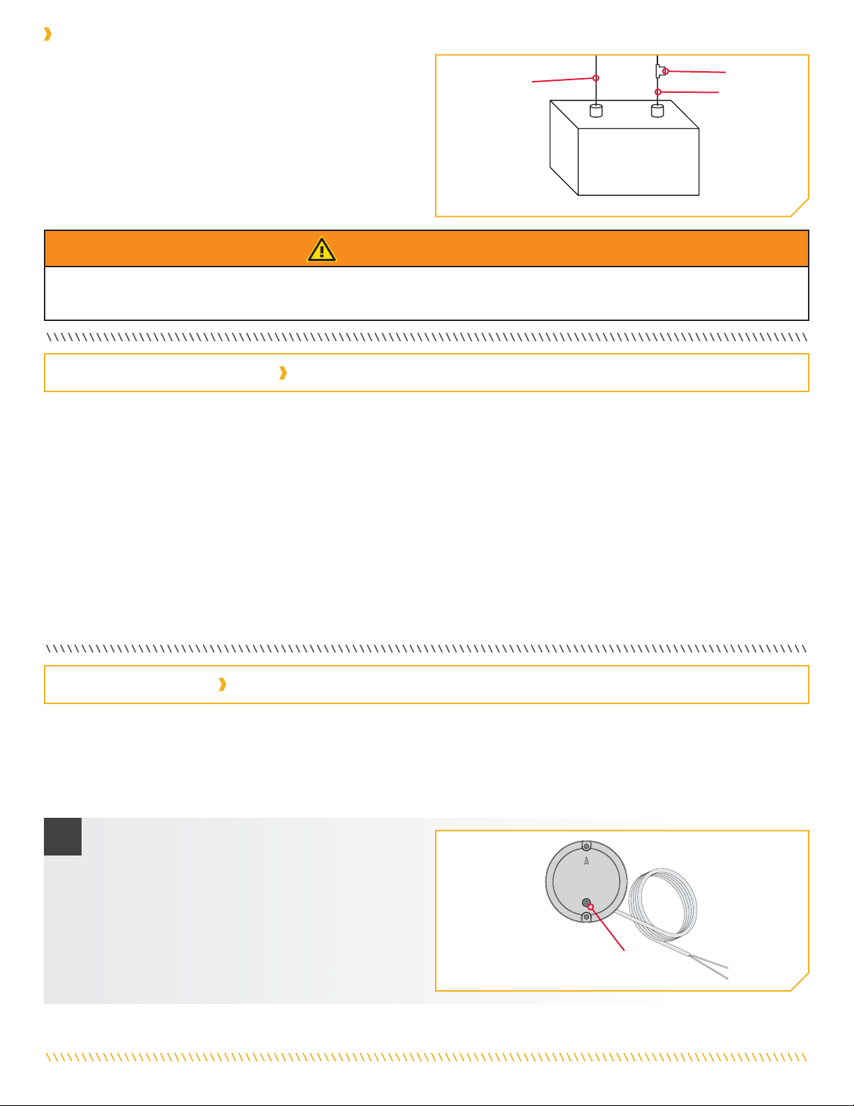
The Heading Sensor is powered by a 12-volt power source. The
Heading Sensor must be set up with a one amp fuse, either
in-line, or connected to a fuse panel. To connect the Heading
Sensor, please follow the directions below.
To Heading
Sensor negative
(black) To Heading
Sensor positive
(red)
Neg - Pos +
Power Source
1. Connect positive ( + ) red lead to positive ( + ) power
source terminal.
2. Connect negative ( – ) black lead to negative ( – ) power
source terminal.
Fuse
Connecting the Heading Sensor to a Power Source
WARNING
Never connect the (+) and the (-) terminals of the same battery together. Take care that no metal object can fall onto the battery and
short the terminals. This would immediately lead to a short and extreme fire danger.
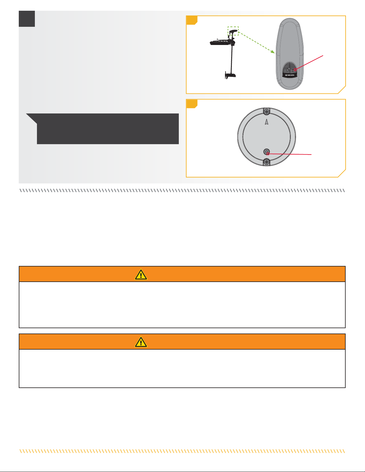
The Heading Sensor displays modes of operation with an LED located on the Pair Button. There are three distinct patterns that the LED
will display to communicate dierent modes of operation. Become familiar with the modes of operation to be sure that the Heading
Sensor is powered up and communicating with the Minn Kota Advanced GPS Navigation system.
The three LED patterns displayed by the Heading Sensor are:
1. Power On - When the Heading Sensor is first connected to a power source, the LED will turn on for three seconds and then turn o.
2. Pairing - The Heading Sensor can be paired to any Bluetooth enabled Advanced GPS Navigation system. While the Heading Sensor
is attempting to pair, the LED will flash on and o twice per second for up to 20 seconds. If the Heading Sensor is successfully
paired, normal operation will begin. If the Heading Sensor is not paired, the LED will turn o.
3. Normal Operation - During normal operation when the Heading Sensor is connected to a power source and paired to and actively
communicating an Advanced GPS Navigation, the LED on the Heading Sensor will flash on and o once every three seconds.
LIGHT PATTERNS
HEADING SENSOR COMMUNICATION
HEADING SENSOR SET-UP
Before the Heading Sensor can be paired, make sure that it has been properly installed and connected to a power source. Review the
LED patterns that the Heading Sensor communicates in order to understand what mode it is in and to be able to recognize that is has
successfully paired once the process is complete. Be sure that the Heading Sensor is being paired to a Minn Kota trolling motor that is
equipped with a Bluetooth compatible Advanced GPS Navigation system. To pair the Heading Sensor:
a. Connect the Heading Sensor to a power source.
Verify that the LED on the Heading Sensor turns on
for 3 seconds and then turns o.
b. Power on the trolling motor. Please see the trolling
motor Owner’s Manual for instructions on how to
power up the trolling motor.
c. Press the Pair button on the Heading Sensor. Verify
that the LED indicates it is attempting to pair.
Pair
Button
PAIRING THE HEADING SENSOR
1

minnkota.johnsonoutdoors.com | 7
©2023 Johnson Outdoors Marine Electronics, Inc.
d. As quickly as possible, begin to hold the Pair button
on the trolling motor Control Head.
e. The trolling motor Control Head will emit a beep
pattern when the Heading Sensor is successfully
paired. Release the Pair button on the Control Head.
Watch the Heading Sensor to be sure that once it
successfully pairs that it starts emitting the LED
pattern for normal operation.
f. After the Heading Sensor is paired with the
trolling motor, proceed to Sensor Calibration and
Sensor Oset.
2d
2e
Pair
Button
LED
NOTICE: If battery power is lost, the Heading Sensor
will not lose its Pairing to the Advanced GPS Navigation
System when it is powered down.
2
The Heading Sensor calibration is initiated using either the Advanced GPS Navigation full featured wireless remote or the One-Boat
Network® app. Refer to the Owner’s Manual for your motor if you are unsure of the remote that comes with your motor. The process of
calibrating the Heading Sensor must occur while your boat is on the water. Heading Sensor Calibration should always be performed
after the trolling motor and Heading Sensor have been mounted, but before the Heading Sensor Oset is performed. The Heading
Sensor must be connected to power and paired with the Control Head of the trolling motor before beginning this process. The calibration
process requires the boat to be driven in two complete circles, so plan accordingly when preparing for this process. To complete this
process, read all safety warnings and follow the procedure below.
HEADING SENSOR CALIBRATION
WARNING
You are responsible for the safe and prudent operation of your vessel. We have designed your Minn Kota product to be an accurate
and reliable tool that will enhance boat operation and improve your ability to catch fish. This product does not relieve you from the
responsibility for safe operation of your boat. You must avoid hazards to navigation and always maintain a permanent watch so you can
respond to situations as they develop. You must always be prepared to regain manual control of your boat. Learn to operate your Minn
Kota product in an area free from hazards and obstacles.
WARNING
Take care that neither you nor other persons approach the turning propeller too closely, neither with body parts nor with objects. The
motor is powerful and may endanger or injure you or others. While the motor is running watch out for persons swimming and for floating
objects. Persons whose ability to run the motor or whose reactions are impaired by alcohol, drugs, medication, or other substances are
not permitted to use this motor.

minnkota.johnsonoutdoors.com | 8
©2023 Johnson Outdoors Marine Electronics, Inc.
Heading Sensor Calibration for Advanced GPS Navigation with the Wireless Remote
a. Review all safety warnings. Navigate your boat to an
area on the water free from obstructions.
b. Power up the trolling motor according to the
instructions provided in the Owner’s Manual. Make
sure the Heading Sensor is powered up and paired
with the trolling motor.
c. Turn on the wireless remote for your Advanced GPS
Navigation system. Make sure the wireless remote is
paired to the trolling motor.
1
d. On the wireless remote, press the Menu button.
e. Use the Speed Down or Speed Up
button to find the Motor Settings menu. Use the
Steer Right button to select Motor Settings.
f. In the Motor Settings menu, use the Speed Down
or Speed Up button to find Setup/
Calibration. Use the Steer Right button to select
Setup/Calibration.
g. In the Setup/Calibration menu, use the Speed Down
or Speed Up button to find Calibrate
Heading Sensor. Use the Steer Right button to
select Calibrate Heading Sensor.
2d 2e
2f 2g
h. Review all safety warnings. Follow the prompts on
the wireless remote. Use the Steer Right button to
select Start and begin the process.
i. Drive the boat in two complete circles. The center
of the Dashboard contains a counter that displays
the progress.
j. The progress of the boat around the circular path will
display as a percentage completed for each circle
while the boat navigates.
k. Once the two circles are complete, the Dashboard will
briefly read “Calibration Successful. Please perform
Sensor Oset.”
l. The Dashboard will then bring up Sensor Oset.
Please perform Sensor Oset. Select Start to
complete Sensor Oset, or press and hold the Menu
button to close and return to the home screen.
3h 3i
3j 3k
2
3

minnkota.johnsonoutdoors.com | 9
©2023 Johnson Outdoors Marine Electronics, Inc.
Heading Sensor Calibration for Advanced GPS Navigation with the One-Boat Network App
a. Review all safety warnings. Navigate your boat to an
area on the water free from obstructions.
b. Power up the trolling motor according to the
instructions provided in the Owner’s Manual. Make
sure the Heading Sensor is powered up and paired
with the trolling motor.
c. Open the One-Boat Network (OBN) app on the mobile
device. Make sure the mobile device is paired with the
trolling motor.
1
d. From the OBN home screen, tap the Motor menu.
The Motor menu opens the Motor app home screen.
e. Before the Motor app home screen will open, tap
Agree on the on-screen prompt.
3g
2e
3h
2f
3i
g. In the Motor Settings menu, find and tap Setup
and Calibration.
h. In Setup and Calibration, find and tap Calibrate
Heading Sensor.
i. Review all safety warnings. Follow the prompts in
the One-Boat Network app. Tap Start to begin
the process.
2
3
4
One-BoatOne-Boat
Network appNetwork app
IconIcon
j. Drive the boat in two complete circles. The center
of the app screen contains a counter that shows
the progress.
k. The progress of the boat around the circular path will
show as a percentage completed for each circle while
the boat navigates.
l. Once the two circles are complete, the app screen
will read “Calibration Successful. Please perform
Sensor Oset.”
m. Please perform Heading Sensor Oest. Tap Start
Sensor Oset to begin or tap to close the Sensor
Calibration and return to the home screen.
f. On the Motor app home screen, locate the Motor
Settings button in the top-right corner and tap it.
NOTICE: The on-screen prompt will only display
once each time the app launches. If the prompt has
displayed, the Motor app home screen appears.
4j 4k 4l
2d

minnkota.johnsonoutdoors.com | 10
©2023 Johnson Outdoors Marine Electronics, Inc.
Heading Oset for Advanced GPS Navigation with the Wireless Remote
a. Turn on the wireless remote for your Advanced GPS
Navigation system. Make sure the wireless remote is
paired to the trolling motor.
b. On the wireless remote, press the Menu button.
c. Use the Speed Down or Speed Up
button to find the Motor Settings menu. Use the
Steer Right button to select Motor Settings.
d. In the Motor Settings menu, use the Speed Down
or Speed Up button to find Setup/
Calibration. Use the Steer Right button to select
Setup/Calibration.
e. In the Setup/Calibration menu, use the Speed Down
or Speed Up button to find Oset
Heading Sensor. Use the Steer Right button to
select Oset Heading Sensor.
f. Review all safety warnings. Follow the prompts on
the wireless remote. Use the Steer Right button to
select Start and begin the process.
g. Use the Steer Right or Steer Left button to point
the motor forward and parallel to the keel.
h. When satisfied with the placement of the trolling
motor, use the Speed Down or Speed Up
button to scroll to Set. Use the Steer Right
button to select Set. The degree of Sensor Oset is
displayed at the bottom of the Dashboard.
i. Press and hold the Menu button to close out
Sensor Oset and return to the home screen.
2f 2g
2h 2i
1
2
1b 1c
1d 1e
With the Heading Sensor calibrated, set the Heading Oset. Heading Oset is the dierence between the angle of the Keel of the boat
and the angle at which the Heading Sensor is mounted to the deck of the boat. During installation, the Heading Sensor was installed to
be as parallel to the Keel of the boat as possible. If the boat and Heading Sensor are perfectly parallel and pointing in exactly the same
direction, the Oset will be a perfect 0° degrees. Knowing that installations are never perfect, the Heading Oset can be set on the
Advanced GPS Navigation or the One-Boat Network® app to compensate for the dierence between the two.
HEADING OFFSET

minnkota.johnsonoutdoors.com | 11
©2023 Johnson Outdoors Marine Electronics, Inc.
Heading Oset for Advanced GPS Navigation with the One-Boat Network App
a. Open the One-Boat Network (OBN) app on the mobile
device. Make sure the mobile device is paired with the
trolling motor.
b. From the OBN home screen, tap the Motor menu.
The Motor menu opens the Motor app home screen.
c. Before the Motor app home screen will open, tap
Agree on the on-screen prompt.
1
2
1b
2e
1c
2f
1d
2g
e. In the Motor Settings menu, find and tap Setup
and Calibration.
f. In Setup and Calibration, find and tap Oset
Heading Sensor.
g. Review all safety warnings. Follow the prompts in
the One-Boat Network app. If the placement of the
trolling motor is pointing forward and parallel to the
keel, tap Set. The degree of Heading Sensor Oset
shows at the bottom of the app Display.
NOTICE: The on-screen prompt will only display once
each time the app is launched. If the prompt has
displayed, the Motor app home screen appears.
d. On the Motor app home screen, locate the Motor
Setting button in the upper right-hand corner and tap it.

For warranty information please visit minnkota.johnsonoutdoors.com.
The Bluetooth® word mark and logos are registered trademarks owned by Bluetooth SIG, Inc. and any use of such marks by Johnson
Outdoors, Inc. is under license. Other trademarks and trade names are those of their respective owners.
Part #2394905 Rev A 09/23
ECN 44290
Minn Kota Consumer & Technical Service
Johnson Outdoors Marine Electronics, Inc.
PO Box 8129
Mankato, MN 56001
121 Power Drive
Mankato, MN 56001
Phone (800) 227-6433
Fax (800) 527-4464
minnkota.johnsonoutdoors.com
©2023 Johnson Outdoors Marine Electronics, Inc.
All rights reserved.
33i
3m
3k
3l
h. If the trolling motor needs to be adjusted, locate
the Return button on the top-left corner of the app
screen. Tap the Return button three times until the
Motor app home screen displays.
i. Use the Steer Right and Steer Left buttons to
point the motor forward and parallel to the keel.
j. When satisfied with the placement of the trolling
motor, locate the Motor Setting button in the
top-right corner and tap it.
k. In the Motor Settings menu, find and tap Setup
and Calibration.
l. In Setup and Calibration, find and tap Oset Heading
Sensor. If the placement of the trolling motor is
pointing forward and parallel to the keel, tap Set.
m. The degree of Heading Sensor Oset shows at
the bottom of the app Display. Tap Return to close
the Heading Sensor Oset and return to the
home screen.
3j

minnkota.johnsonoutdoors.com | 13
©2023 Johnson Outdoors Marine Electronics, Inc.
Compatible avec tous les systèmes de navigation GPS Bluetooth® avancés de Minn Kota.*
2
1
A
Article/
Ensemble Nº de
pièce Description Qté
A 2996400 HEADING SENSOR ASSEMBLY 1
1 2393400 SCREW-#8-18X1-1/2 PPH TY AB SS
*STAINLESS STEEL* 2
2✖HEADING SENSOR 1
✖Cette pièce est incluse dans un ensemble et ne peut pas être commandée individuellement.
Avant d’installer votre capteur de cap, tenez compte des facteurs suivants :
1. Le capteur de cap contient une boussole qui détecte
un champ magnétique. N’installez pas le capteur de
cap près de métaux ferreux ou de câbles qui transportent
de puissants courants, comme des batteries ou des
câbles d’alimentation.
2. Pour un rendement maximal, installez le capteur de cap
dans un endroit ayant une ligne de communication libre
avec la tête du moteur qui est installé avec un système de
navigation GPS avancé Minn Kota pour un rendement optimal.
PRINCIPE DE FONCTIONNEMENT
FACTEURS DE MONTAGE
ATTENTION
Les aimants et les grands objets de métal ferreux peuvent
nuire au fonctionnement du capteur de cap. N’installez pas
le capteur de cap à moins de 24 po (61 cm) de ceux-ci, car ils
causeront une interférence.
Le capteur de cap Minn Kota fournit de l’information sur le cap du bateau aux moteurs de pêche à la traîne Minn Kota avec système de
navigation GPS avancé. Il possède une boussole qui détecte le cap du bateau. Le système utilise le cap pour des fonctions de navigation
comme le déplacement du Spot-Lock. Le capteur de cap ne contient pas de récepteur GPS, et ne modifie pas ni ne contrôle l’orientation
du bateau. Le capteur de cap Minn Kota peut uniquement communiquer avec les autres produits Minn Kota compatibles Bluetooth.
AVIS : Le capteur de cap n’est pas standard avec tous les
modèles. On peut l’acheter en tant qu’accessoire. Pour en
apprendre davantage sur les accessoires de Minn Kota,
veuillez visiter minnkota.johnsonoutdoors.com.
Fonctions du capteur de cap
AVERTISSEMENT
Il ne faut pas utiliser le capteur de cap en tant qu’aide à la navigation pour prévenir les collisions, l’échouement, les dommages au bateau
ou les blessures. Lorsque le bateau se déplace, la profondeur de l’eau pourrait changer trop rapidement pour que vous ayez le temps de
réagir. Naviguez toujours à des vitesses très basses si vous soupçonnez que l’eau est peu profonde ou qu’il y a des objets submergés.
N’installez pas le capteur de cap près de métaux ferreux ou de tout autre objet qui pourrait créer un champ ou une interférence
magnétiques. Le capteur de cap doit être installé à 24 po (61 cm) ou plus des matériaux magnétiques ou ferreux sur le bateau, y
compris la base du moteur. On doit aussi éviter l’installation à proximité des fils de sortie du moteur en raison des champs magnétiques
qui sont créés lors de situations de consommation élevée de courant.
ENSEMBLE DE CAPTEUR DE CAP
1866680
*Ne s’applique pas aux moteurs de pêche à la traîne de la série
QUESTTM dotés d’un capteur de cap interne.

minnkota.johnsonoutdoors.com | 14
©2023 Johnson Outdoors Marine Electronics, Inc.
• Perceuse
• Mèche de 1/4 po (6,4 mm)
• Tournevis nº 2
• Mèche de 9/64 po (3,6 mm)
• Poinçon ou autre outil de
marquage semblable
• Silicone de qualité marine
OPTIONS DE MONTAGE
Il y a deux options pour installer le capteur de cap. Établissez si le câble d’alimentation du capteur de cap passera sous la surface de montage.
1. Accès sous l’emplacement de montage - Lorsque vous installez le capteur de cap avec cette option, les câbles d’alimentation provenant du
capteur de cap passeront sous la surface de montage. Choisissez cette option uniquement si on peut accéder aux câbles après qu’ils aient
été passés au travers de la surface de montage. Suivez les instructions dans la section Installation avec accès sous l’emplacement de
montage de ce feuillet d’instruction.
2. Installation sans accès sous l’emplacement de montage - Les câbles d’alimentation du capteur de cap seront acheminés vers le côté, car il n’y a
pas d’espace pour passer les fils sous l’emplacement de montage ou la zone sous l’emplacement de montage n’est pas accessible. Suivez
les instructions de la section Installation sans accès sous l’emplacement de montage de ce feuillet d’instruction.
Il est important d’examiner les facteurs de montage et de tester le câble d’alimentation avant l’installation.
OUTILS ET RESSOURCES NÉCESSAIRES
INSTALLATION
Placement
du capteur
de cap
Placement
du capteur
de cap
Placement
du capteur
de cap
CâbleCâble
d’alimentationd’alimentation
EmplacementEmplacement
percépercé
Emplacement marqué
Emplacement percé
1c 1d
1a 1b
a. Passez en revue les facteurs d’installation, puis
placez le capteur de cap (article nº 2) à plat sur
l’emplacement de montage sélectionné et
notez l’emplacement.
b. Enlevez le capteur de cap et marquez un point avec
un poinçon ou un outil de marquage semblable
sous l’emplacement de montage, où le câble
d’alimentation passera au travers de la surface.
c. À l’aide d’une perceuse avec une mèche de
1/4 po (6,4 mm), percez un trou au travers de
l’emplacement de montage.
d. Acheminez le câble d’alimentation au travers du trou
percé et introduisez tout le câble jusqu’à ce que le
capteur de cap repose à plat sur l’emplacement de
montage et que tout le câble soit passé au travers du
trou percé.
#2 x 1
Installation avec accès sous l’emplacement de montage
1ARTICLE(S) REQUIS
3. Assurez-vous que la zone sous l’emplacement d’installation est horizontale, qu’on peut y percer des trous et que la quincaillerie
d’installation n’endommagera pas de composantes en place sous la surface de montage.
4. Vérifiez que le câble d’alimentation du capteur de cap est assez long pour atteindre la source d’alimentation à partir de
l’emplacement de montage désiré. Si le câble ne se rend pas jusqu’à la batterie ou à la source d’alimentation prévue, choisissez un
emplacement plus près de la source.
5. Montez le capteur de cap de façon horizontale. Il ne doit pas être monté à l’envers.

minnkota.johnsonoutdoors.com | 15
©2023 Johnson Outdoors Marine Electronics, Inc.
e. Placez le capteur de manière à ce que la flèche sur
le couvercle pointe vers l’avant du bateau, dans le
sens du déplacement. La flèche doit être parallèle à la
quille du bateau.
Quille du
bateau
Placement
parallèle
Flèche
vers l’avant
g. Mettez le capteur de cap de côté et percez deux
trous à l’aide d’une mèche de 9/64 po (3,6 mm) aux
emplacements marqués.
f. Marquez l’emplacement des deux trous de
vis avec un poinçon ou un autre outil de
marquage semblable.
Emplacements
marqués des
trous de vis
Trous
de vis
Emplacement de
montage avec
accès
Câble
d’alimentation
h. Remettez le capteur de cap en place de manière
à ce que les trous percés dans l’emplacement de
montage s’alignent avec les trous dans le capteur de
cap et que le câble d’alimentation soit entièrement
passé dans le trou. Assurez-vous de monter le capteur de
manière à ce que la flèche pointe vers l’avant du bateau et
qu’elle soit parallèle à la quille du bateau.
Quille
du
bateau
Placement
parallèle Câble
d’alimentation
Flèche
vers
l’avant
Emplacement de
montage avec
accès
Trous
de vis
2
3
4
ATTENTION
Un mauvais alignement du capteur de cap mènera à des
lectures incorrectes de la boussole.
ATTENTION
Un mauvais alignement du capteur de cap mènera à des
lectures incorrectes de la boussole.
ATTENTION
Si la surface de montage est mince ou faite d’un matériau léger, il faudra probablement la renforcer afin qu’elle supporte le capteur
de cap. Serrez la vis de montage à la main pour éviter un serrage excessif et pour empêcher les dommages à l’emplacement de
montage et au capteur de cap.
Placement du
capteur de cap

minnkota.johnsonoutdoors.com | 16
©2023 Johnson Outdoors Marine Electronics, Inc.
#1 x 2
i. Appliquez un scellant ou un calfeutrage de silicone de
qualité marine aux deux vis nº 8 - 18 x 1 1/2 (3,81 cm)
(article nº 1) tel que requis afin de protéger votre
bateau contre les dommages causés par l’eau.
j. En utilisant un tournevis nº 2 et les deux vis, montez
le capteur de cap à l’emplacement de montage.
Serrez uniquement à la main.
a. Passez en revue les facteurs d’installation,
puis placez le capteur de cap (article nº 2) à
plat sur l’emplacement de montage et notez
son emplacement.
b. Acheminez le câble d’alimentation par une des
deux encoches dans la base du capteur de cap.
Lorsque la flèche sur le capteur de cap pointe
vers l’avant du bateau, le câble devrait sortir du
capteur de cap dans le sens le plus près de la source
d’alimentation prévue.
#2 x 1
5j
Placement
du capteur
de cap
Câble
d’alimentation
à la batterie
Encoche
1a 1b
Vis
VisVis
5i
AVIS : s’il faut utiliser des vis de remplacement, assurez-
vous qu’elles sont fabriquées en acier inoxydable non
magnétique de haute qualité.
5ARTICLE(S) REQUIS
Installation sans accès sous l’emplacement de montage
1ARTICLE(S) REQUIS
c. Vérifiez à nouveau la position du capteur de cap;
assurez-vous que la flèche sur le couvercle pointe
vers l’avant du bateau, dans le sens de déplacement.
La flèche doit être parallèle à la quille du bateau. Quille
du
bateau
Placement parallèlePlacement parallèle
Trous
de vis
CâbleCâble
d’alimentationd’alimentation
Flèche
vers
l’avant
EmplacementEmplacement
de montage sansde montage sans
accèsaccès
ATTENTION
Un mauvais alignement du capteur de cap mènera à des
lectures incorrectes de la boussole.
2

minnkota.johnsonoutdoors.com | 17
©2023 Johnson Outdoors Marine Electronics, Inc.
f. Remettez le capteur de cap en place de manière
à ce que les trous percés dans l’emplacement de
montage s’alignent avec les trous dans le capteur de
cap. Assurez-vous de monter le capteur de manière à ce que la
flèche pointe vers l’avant du bateau et qu’elle soit parallèle à la
quille du bateau.
g. Appliquez un scellant ou un calfeutrage de silicone
de qualité marine aux deux vis nº 8 - 18 x 1 1/2 (3,81
cm) (article nº 1) tel que requis afin de protéger votre
bateau contre les dommages causés par l’eau.
Placement du
capteur de cap
Emplacements
marqués des
trous de vis
d. Marquez l’emplacement des deux trous de vis avec
un poinçon ou un autre outil de marquage semblable.
e. Mettez le capteur de cap de côté et percez deux
trous à l’aide d’une mèche de 9/64 po (3,6 mm) aux
emplacements marqués.
#1 x 2
Quille
du
bateau
CâbleCâble
d’alimentationd’alimentation
Trous
de vis
PlacementPlacement
parallèleparallèle
FlècheFlèche
versvers
l’avantl’avant
EmplacementEmplacement
de montagede montage
sans accèssans accès
ATTENTION
Un mauvais alignement du capteur de cap mènera à des
lectures incorrectes de la boussole.
3
4ARTICLE(S) REQUIS
h. En utilisant un tournevis nº 2 et les deux vis, montez
le capteur de cap à l’emplacement de montage.
Serrez uniquement à la main. Vis
VisVis
AVIS : s’il faut utiliser des vis de remplacement, assurez-
vous qu’elles sont fabriquées en acier inoxydable non
magnétique de haute qualité.
5
ATTENTION
Si la surface de montage est mince ou faite d’un matériau
léger, il faudra probablement la renforcer afin qu’elle supporte
le capteur de cap. Serrez la vis de montage à la main pour
éviter un serrage excessif et pour empêcher les dommages à
l’emplacement de montage et au capteur de cap.
4f

minnkota.johnsonoutdoors.com | 18
©2023 Johnson Outdoors Marine Electronics, Inc.
Le capteur de cap est alimenté par une source d’alimentation de
12 volts. Le capteur de cap doit être configuré avec un fusible d’un
ampère, soit en ligne, soit branché à un tableau de fusibles. Pour
brancher le capteur de cap, veuillez suivre les directives ci-dessous.
Vers le fil
négatif du
capteur de
cap (noir)
Vers le fil
positif du
capteur de
cap (rouge)
Nég. - Pos. +
Source d’alimentation
1. Raccordez le fil rouge positif (+) à la borne positive (+)
de la source d’alimentation.
2. Raccordez le fil noir négatif (–) à la borne négative (–)
de la source d’alimentation.
Fusible
Connexion du capteur de cap à une source d’alimentation
AVERTISSEMENT
Ne connectez jamais les bornes (+) et (–) de la même batterie ensemble. Assurez-vous qu’aucun objet métallique ne puisse tomber sur la
batterie et provoquer un court-circuit entre les bornes. Cela provoquerait immédiatement un court-circuit et un risque extrême d’incendie.
Le capteur de cap ache les modes de fonctionnement grâce à une DEL située sur le bouton Couplage (Pair). La DEL ache trois
séquences distinctes pour indiquer les diérents modes de fonctionnement. Familiarisez-vous avec les modes de fonctionnement pour
vous assurer que le capteur de cap est sous tension et communique avec le système de navigation GPS avancé Minn Kota.
Voici les trois séquences qu’ache la DEL du capteur de cap :
1. Sous tension : Lorsque le capteur de cap est connecté à une source d’alimentation pour la première fois, la DEL s’allumera
pendant 3 secondes puis s’éteindra.
2. Jumelage – Le capteur de cap peut être jumelé à n’importe quel système de navigation GPS avancé Bluetooth. Lorsque le capteur
de cap tente de se coupler, la DEL clignotera deux fois par seconde pendant un maximum de 20 secondes. Si le couplage du
capteur de cap réussit, le fonctionnement normal commencera. Si le capteur de cap n’est pas couplé, la DEL s’éteindra.
3. Fonctionnement normal – Pendant le fonctionnement normal, lorsque le capteur de cap est connecté à une source d’alimentation,
couplé à un système de navigation GPS avancé, la DEL du capteur de cap clignotera toutes les 3 secondes.
SÉQUENCES LUMINEUSES
COMMUNICATION DU CAPTEUR DE CAP
CONFIGURATION DU CAPTEUR DE CAP
Avant le couplage du capteur de cap, assurez-vous qu’il est bien installé et connecté à une source d’alimentation. Examinez les séquences de
la DEL indiquées par le capteur de cap afin de comprendre le mode dans lequel il se trouve et d’être en mesure de reconnaître un couplage
réussi après la fin de ce processus. Assurez-vous que le capteur de cap est couplé à un moteur de pêche à la traîne Minn Kota équipé d’un
système de navigation GPS avancée compatible avec Bluetooth. Pour coupler le capteur de cap :
a. Connectez le capteur de cap à une source
d’alimentation. Assurez-vous que la DEL sur le
capteur de cap s’allume pendant 3 secondes
puis s’éteint.
b. Mettez le propulseur électrique sous tension. Veuillez
consulter le manuel du propriétaire du propulseur
électrique pour savoir comment mettre le propulseur
électrique sous tension.
c. Appuyez sur le bouton Couplage (Pair) sur le capteur
de cap. Vérifiez que la DEL indique qu’il tente de
se coupler.
Bouton Pair
(couplage)
COUPLAGE DU CAPTEUR DE CAP
1

minnkota.johnsonoutdoors.com | 19
©2023 Johnson Outdoors Marine Electronics, Inc.
d. Aussi rapidement que possible, appuyez et tenez le
bouton de jumelage sur la tête de contrôle du moteur
de pêche à la traîne.
e. La tête du moteur de pêche à la traîne émettra une
séquence de signaux sonores lorsque le capteur
de cap est jumelé. Relâchez le bouton de couplage
sur la tête de contrôle. Examinez le capteur de cap
pour vous assurer que, une fois le couplage réussi,
il émet la séquence lumineuse DEL indiquant un
fonctionnement normal.
f. Lorsque le capteur de cap est jumelé au moteur de
pêche à la traîne, passez à la calibration du capteur
et au décalage du capteur.
2d
2e
Bouton Pair
(couplage)
DEL
AVIS : Si l’alimentation de la batterie est coupée,
le capteur de cap ne perdra pas son couplage avec le
système lorsqu’il est mis hors tension.
2
L’étalonnage du capteur de cap est lancé à l’aide de la télécommande sans fil à fonctions complètes de navigation GPS avancée at
de l’application One-Boat Network®. Consultez le manuel du propriétaire de votre moteur si vous ne savez pas avec certitude quelle
télécommande est incluse votre moteur. Vous devrez calibrer le capteur de cap pendant que votre bateau est sur l’eau. La calibration du
capteur de cap doit toujours être eectuée lorsque le propulseur électrique et le capteur de cap ont été montés, mais avant le décalage
du capteur de cap. Le capteur de cap doit être connecté à une source d’alimentation et couplé avec la tête de commande du propulseur
électrique avant le début du processus. Pour le processus de calibration, le bateau doit eectuer deux cercles complets. Planifiez en
conséquence lors de la préparation de ce processus. Pour exécuter ce processus, lisez toutes les mises en garde et suivez la
procédure ci-dessous.
CALIBRATION DU CAPTEUR DE CAP
AVERTISSEMENT
Vous seul êtes responsable de la navigation sécuritaire et prudente de votre bateau. Nous avons conçu votre produit Minn Kota pour
qu’il soit un outil précis et fiable qui vous permettra d’améliorer l’utilisation de votre bateau et d’accroître votre capacité de pêcher
des poissons. Ce produit ne vous exonère pas de la responsabilité de naviguer en toute sécurité avec votre bateau. Vous devez éviter
les dangers liés à la navigation et toujours exercer une veille permanente afin de pouvoir réagir au fur et à mesure que les situations se
présentent. Vous devez toujours être prêt à reprendre le contrôle manuel de votre bateau. Apprenez à utiliser votre produit Minn Kota
dans une zone exempte de dangers et d’obstacles.
AVERTISSEMENT
Veillez à ce que ni vous, ni les autres personnes ne s’approchent trop près de l’hélice en rotation, que ce soit seulement avec une partie
du corps ou des objets. Le moteur est puissant et pourrait provoquer des situations périlleuses ou des blessures, pour vous ou les
autres. Lorsque le moteur est en marche, méfiez-vous des objets flottants ou des personnes qui pourraient être en train de nager. Les
personnes, dont les réactions ou la capacité à faire fonctionner le moteur est/sont aaiblie(s) par l’alcool, la drogue, les médicaments
ou d’autres substances, ne sont pas autorisées à utiliser ce moteur.

minnkota.johnsonoutdoors.com | 20
©2023 Johnson Outdoors Marine Electronics, Inc.
Étalonnage du capteur de cap pour la navigation GPS avancée avec la télécommande sans fil
a. Passez en revue tous les avertissements de sécurité.
Naviguez dans votre bateau jusqu’à une zone de
l’eau libre d’obstructions.
b. Mettez le propulseur électrique sous tension
conformément aux instructions du manuel du
propriétaire. Assurez-vous que le capteur de cap
est également sous tension et jumelé avec le
propulseur électrique.
c. Allumez la télécommande sans fil pour votre
système de navigation GPS avancé. Assurez-vous
que la télécommande sans fil est jumelée au
propulseur électrique.
1
d. Appuyez sur le bouton Menu de la
télécommande sans fil.
e. Utilisez le bouton Réduire la vitesse ou
Augmenter la vitesse pour trouver le menu
Réglages du moteur. Utilisez le bouton Direction
droite pour sélectionner Réglages du moteur.
f. Dans le menu Réglages du moteur, utilisez le bouton
Réduire la vitesse ou Augmenter la vitesse
pour trouver Configuration/Étalonnage.
Utilisez le bouton Direction droite pour
sélectionner Configuration/Étalonnage.
g. Dans le menu Configuration/Étalonnage, utilisez
le bouton Réduire la vitesse ou Augmenter
la vitesse pour trouver Calibrer le capteur
de cap. Utilisez le bouton Direction droite pour
sélectionner Calibrer le capteur de cap.
2d 2e
2f 2g
h. Passez en revue tous les avertissements de sécurité.
Suivez les instructions sur la télécommande sans fil.
Utilisez le bouton Direction droite pour sélectionner
Commencer et commencer le processus.
i. Conduisez le bateau pour faire deux cercles
complets. Le centre du tableau de bord comporte
un compteur qui ache la progression.
j. La progression du bateau autour du trajet circulaire
s’achera sous forme de pourcentage complété pour
chaque cercle pendant que le bateau navigue.
k. Une fois les deux cercles terminés, le tableau de bord
indiquera brièvement « Étalonnage réussi. Veuillez
eectuer le décalage du capteur. »
l. Le tableau de bord achera alors le décalage du
capteur. Veuillez eectuer le décalage du capteur.
Sélectionnez Commencer pour terminer le décalage
du capteur ou appuyez sur le bouton Menu
et maintenez-le enfoncé pour fermer et revenir à
l’écran d’accueil.
3h 3i
3j 3k
2
3
Table of contents
Languages:
Popular Security Sensor manuals by other brands

Broadcast Tools
Broadcast Tools DSD-2 Installation and operation manual

schmersal
schmersal CSS 8-180 operating instructions

B.E.G.
B.E.G. LUXOMAT PD4-M-1C-C-SM Installation and operating instruction

Jaycar
Jaycar LA5172 manual

Eaton
Eaton MAB50R Installation and operation manual

LI-COR
LI-COR LI-210R instruction manual

PCB Piezotronics
PCB Piezotronics W109C12/038CY010AC Installation and operating manual

IFM
IFM SBZ224 operating instructions

DINUY
DINUY KNX DM KNT 003 instruction manual

Inovonics
Inovonics EchoStream ES1265 Installation and operation manual

OPPLE
OPPLE LEDSmart-BLE2-Rc-MW-Sensor quick start guide

Reer
Reer EOS4 Series Installation, use and maintenance