Activating the solenoid valve and adjusting the sensor settings
To activate the solenoid valve swipe the hand across the sensor. The solenoid valve will stay open for a
preset time and will then switch off automatically. Various time settings can be set with the remote control.
While the solenoid valve is active it also can be switched off manually. Just swipe the hand over the sensor
and the valve will switch off.
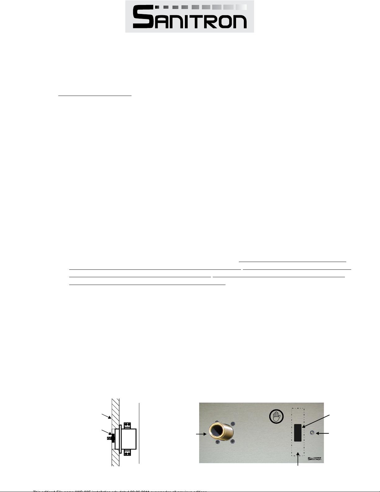
The sensor
The settings of the sensor can be customised to meet individual requirements. Adjustments are carried out
with the optional remote control Art. No 300.102. The remote control works with any IWS-03F.... Trim set.
The settings can be changed at any time and are not lost when the power to the sensor is disconnected.
If the factory pre-sets are adequate, no adjustments are required. If you have product IWS-03F,F the electronics will
automatically activate a flushing cycle for 20 seconds if the sensor has not been activated for 24 hours.
The factory settings of the sensor
Run-time before auto shut off: Approximately 4 seconds .
Detection distance of the sensor: Approximately 100mm
Auto run-time range setting: Program1
Adjusting the sensor with the remote control
To change settings point the remote control towards the sensor from approximately 500mm distance
and press the desired button. Once the sensor has received the signal and has changed its setting it will
acknowledge it by flashing. The remote control has 5 buttons that can perform the following adjustments.
The button 5 makes it quicker to select run-time settings by skipping through different programs.
Push button 5 repeatedly to skip forward through the programs. When the next program is
selected the sensor acknowledges it by flashing the number of times indicating the program number it is set
at (eg. program 5 the sensor will flash 5 times). There are 6 programs.
Program 1: Range between min. 3 seconds and max. 15 seconds. One second steps-per push
Program 2: Range between min. 15 seconds and max. 30 seconds. One second steps-per push
Program 3: Range between min. 30 seconds and max. 45 seconds. One second steps-per push
Program 4: Range between min. 45 seconds and max. 60 seconds. One second steps-per push
Program 5: Range between min. 60 seconds and max. 3 minutes. 15 second steps-per push
Program 6: Range between min. 3 minutes and max. 8minutes. 30 second steps-per push
Button Function Comment
1 Extend detection distance max. distance 150mm
2 Shorten the detection distance min. distance 50mm.
3 Extend run-time, Depends on program
4 Shorten run-time Depends on program
5 Select auto-run time range 6 Programs
Trouble shooting
No water when activating
>> Check that the power is switched on, transformer is plu ged in, battery is connected, batteries are charged, all cable connectors are g
plugged in and the water is turned on. The batteries are not covered under warranty.a
Detection range to shorto or too far
>> Extend or shorten detection range with the remote control
Water stays on too long or too short
>> Extend or shorten the run time with the remote control
>>
If above checks
did not fix the pro
blem please contac
t service.
Ph. 07 3875 2465, or via email: [email protected]Note: FFL = Finished floor level; Technical details, layouts are schematic only; all details for construction by others; dimensions & technical information can change without further notice.
This edition1,File name IWS-03F installation.cdr, dated 02.06.2011 supercedes all previous editions