SANKI S-CON FRAT BF Service manual

1
OPERATING AND SERVICE MANUAL
S-CON®FRAT(BF,BFG and BFGS Models)
S-CON®BT(BT and BTG Models)

2
Thank you very much for purchasing our S-CON®FLAT/BT. To use the machine
properly, please read this operating and service manual carefully before use. Keep
the manual where the machine is installed, so that it may be referred to when needed.
For the following models, refer to the separate operating and service manual:
S-CON®BABY (SBF and SBT models)
TABLE OF CONTENTS
1.Caution When Handling …………………………………
2.Component Names ………………………………………
3.Assembly ……………………………………………………
4.Running the Conveyor ……………………………………
5.Taking up the Belt …………………………………………
6.Belt Alignment Adjustment ……………………………
7.Belt Replacement …………………………………………
8.Motor-pulley/Geared-motor Replacement …………
9.Removal of Pulleys and Rollers ………………………
10.Inspection and Maintenance ……………………………
4
8
13
21
23
25
33
36
39
41

3
Upon delivery of this product, check the package contents to ensure the product
matches your order. If the delivered items do not match your order, please contact
our local agent directly before use.
NOTE: When referring to this manual, confirm the conveyor model code and read
the appropriate pages.
Frequency
Code
50Hz
A
60Hz
B
Drive positon
Code
Head drive
H
Center drive
C
Power source type
Code
100V single-phase
1
200V single-phase
2
200V three-phase
3
other
0
Motor output
Code
0.4kW
04
0.75kW
07
1.0kW
10
1.5kW
15
2.2kW
22
Motor type
Code
Constant speed
C
Variable speed
F
Serial number and model label
(affixed to side of frame)
Serial number and model label
Manufacturer’s serial number(Refer to this number when contacting us)
Job. NO :
TYPE :
SPECIFICATIONS
CAPACITY : T/H KG/M
BELT SPEED : M/MIN
BELT WIDTH : CM
LENGTH : M
GEARED MOTOR : KW RATIO.
MOTORIZED PULLEY: KW
ELECTRIC SOURCE : V Hz
WEIGHT : KG DATE:
ENGINEERING
CO., LTD.
CAUTIONS FOR OPERATION
1. BEFORE OPERATION, TAKE MEASURE
OF INSULATION RESISTANCE, FIRST.
BE SURE TO GROUND FROM THE
EARTH RECEPTACLE PROVIDED IN
THE CONNECTOR.
2. DURING OPERATION, IF THE MOTOR
MAKES AN ABNORMAL SOUND OR
FAILS TO START, SWITCH OFF THE
CURRENT AT ONCE AND SEE IF THE
CURRENT HAS CHANGED TO SINGLE
PHASE.
Manufacturers serial number (Refer to this number when contacting us)
Date of production
[Example of “TYPE”]
BF 35 –6.7 H (C 10 –3 A35 )L –BF
Conveyor model code
Belt width in cm(eg 35cm)
Machine length(total length)in m(eg
6.7m)
NOTE: For fixed inclined type,
machine length is shown as below.
- L1 +L2
(L1: length of inclined area,
L2: length of horizontal area)
Drive position of BF and BFG models
(eg Head drive)
NOTE: For BT and BTG models,
drive position code is not shown.
Motor type
(eg Constant speed)
Motor output
(eg 1.0kW)
Power source
(eg 200V three-phase)
Power source frequency
and belt speed in m/min
(eg 50Hz, 35m/min)
This code is shown only for
geared motor type with chain
cover attached on left side of
direction of belt travel.
Belt type

4
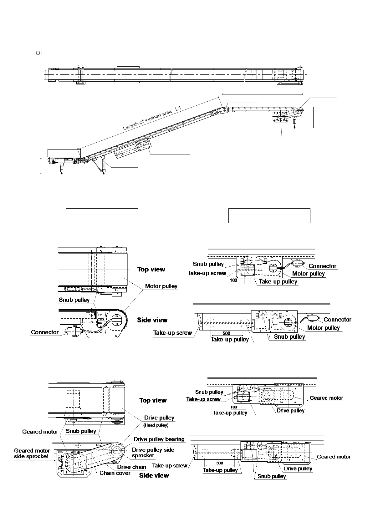
□When using in a high or inclined position:
FOR YOUR SAFE USAGE
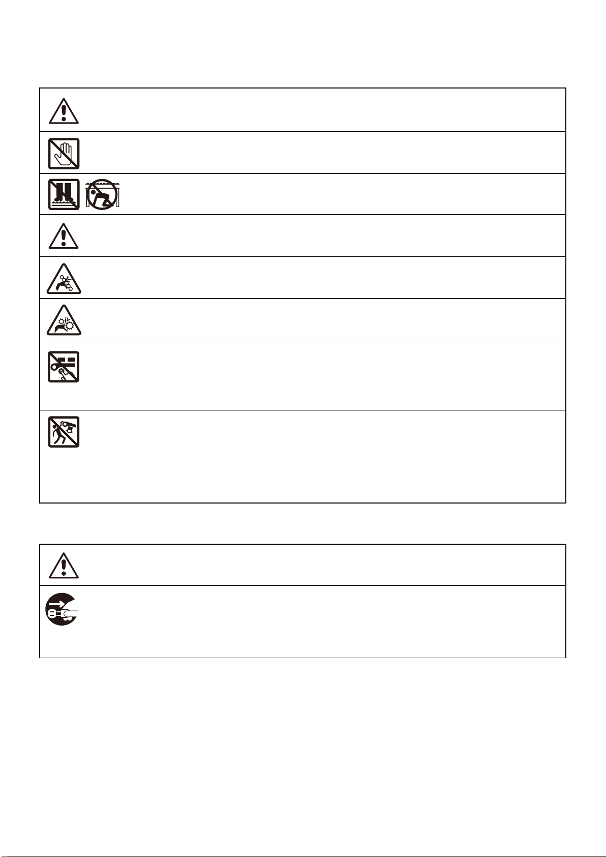
CAUTION : Improper handling of the conveyor may result in physical injury or damage!
■Transport and assembly
When transporting and assembling the conveyor, pay special attention not to drop it in order to
avoid physical injury or damage. When lifting by crane, pay attention to the balance of the conveyor.
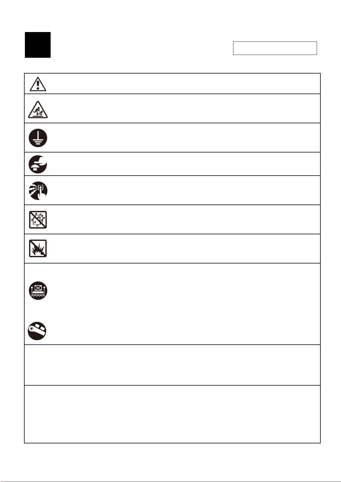
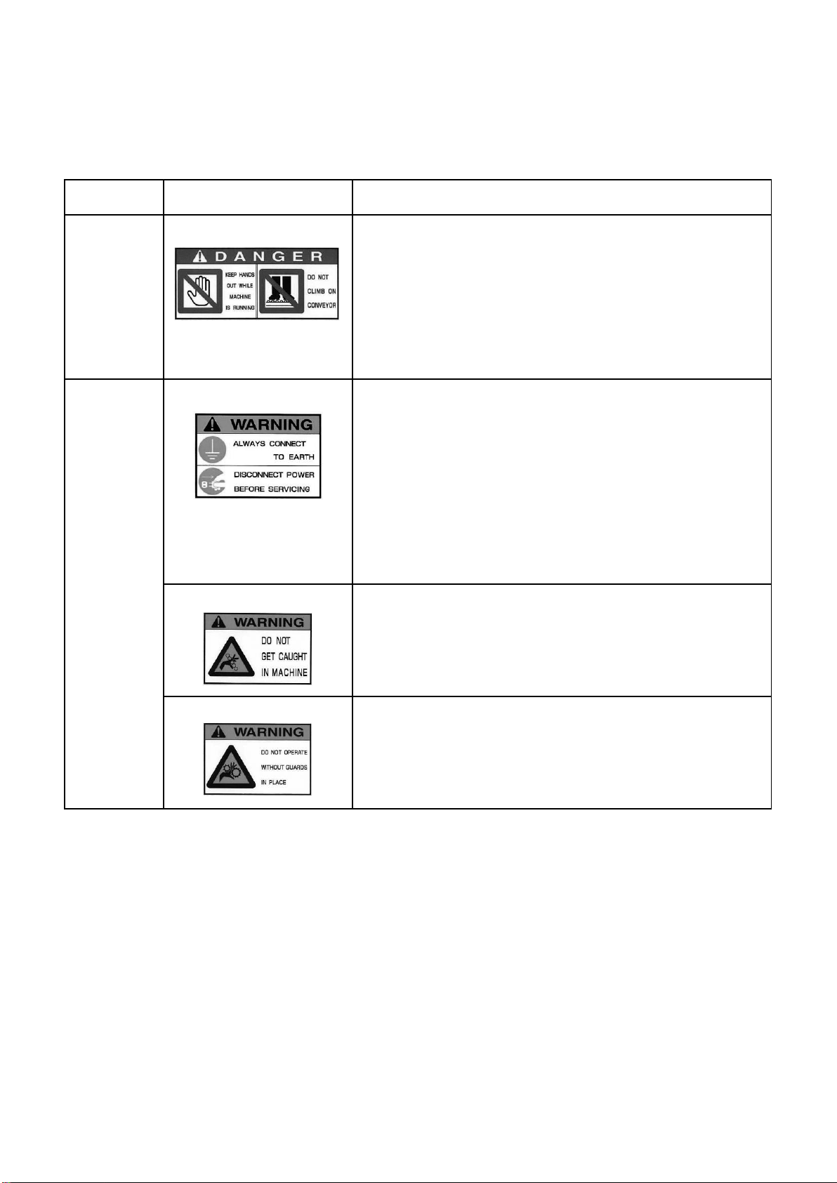
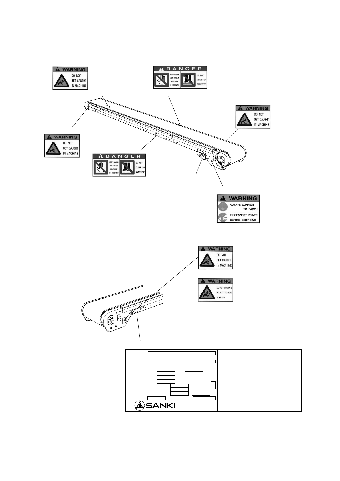
■Earth and leakage breaker
Ensure the conveyor is connected to earth at all times to prevent electric shock. Also ensure that
an earth leakage breaker is connected to the power supply.
A. Prior To Use
■Emergency stop
Install an emergency stop device to immediately stop the conveyor in emergency.
■Start alarm
If it is not possible to supervise the operation of the full length of the conveyor from the operating
position, install a start alarm for increased safety.
■Keep the conveyor dry at all times
Do NOT use the conveyor in wet or humid areas. Do NOT splash liquids onto the conveyor. Use
the waterproof type (optional) if necessary.
■Do NOT use in an explosive atmosphere
(Avoid explosive gas, explosive dust, etc.)
■Lower cover and guard
Install the optional lower cover or guard in order to prevent entry under the conveyor.
■Guide rail, top and side covers
To prevent objects from falling off the conveyor, install the optional guide rail, top and/or side
covers.
■Braking system
When using the conveyor on an incline, it is recommended that an optional braking system be
installed, in order to prevent reverse or other incorrect running of the conveyor.
■Environmental conditions
Ambient temperature
Ambient humidity
Atmosphere
Elevation
NOTE:
●Using the conveyor in a strong electric field (eg near broadcasting devices or high- frequency welding
machinery/equipment) could cause the conveyor to malfunction. In this case, install the conveyor at a
sufficient distance. Alternatively shield completely to avoid any interference with the conveyor.
●Using an inverter to this machine could cause other machines to get effects of high-frequency. In this
case, install the conveyor at a sufficient distance or shield completely.
1
CAUTION WHEN HANDLING
:0℃ to +40℃
:RH 90% max(Avoid condensation)
:Indoor(Avoid corrosive gases, dust, etc.)
:1,000m or less

5
B. During Operation
C. After Use
WARNING:Improper handling of the conveyor could result in serious physical injury or damage!
■Do NOT touch the conveyor when it is running
There is considerable risk of being caught and injured by the conveyor.
■Do NOT ride on or climb on the conveyor/Do NOT go under the conveyor
There is considerable risk of falling or being caught and injured by the conveyor.
■Beware of entanglement
When working close to the conveyor, take care not to get caught in the conveyor. There is
considerable risk of being injured by the conveyor.
■Do NOT remove safety covers
There is a risk of getting caught in the rotating parts such as pulleys. Only remove in case of
maintenance or inspection.
CAUTION:Improper handling of the conveyor may result in physical injury or damage!
■Do NOT apply force to ends of conveyor
Do NOT press down on, or hang off the sides of the conveyor. Injury may result from a toppling
conveyor.
■Secure the conveyor to the floor/ground
When using the conveyor, be sure to secure it to the floor/ground with anchor bolts etc. to
prevent it from toppling irrespective of indoor use or outdoor use.
■Switch off the power after use
Ensure that the power is switched off when carrying out relocation, inspection, cleaning, etc. of
the conveyor, otherwise there is a risk that the conveyor could start unexpectedly. When leaving
the conveyor unused for a long period, take plug out of the outlet /connector to prevent electric
shock or leakage.
NOTE:1. Always use in accordance with the Occupational Safety and Health Act.
2. If the owner modifies the conveyor, any ill effects will fall outside the conditions of the guarantee.
■Do NOT start the conveyor while it is loaded
The motor may become damaged due to overload. Additionally, the motors of variable-speed type
machines may burn out as a result of running at excessively low speeds for
long periods. Use the conveyor within the specifications, indicated in the instructions for use, and
in the catalogue.
CAUTION:Improper handling of the conveyor may result in physical injury or damage!

6
■WARNING LABELS etc. AND ATTACHMENT POSITIONS
For standard machines, warning labels etc. and their attachment positions are as follows:
1. WARNING LABELS
Label classification
Label
Instruction
A-1
■KEEP HANDS OUT WHILE MACHINE IS RUNNING
There is considerable risk of being caught and
injured by the conveyor.
■DO NOT CLIMB ON CONVEYOR
There is considerable risk of falling or being caught
and injured by the conveyor.
DANGER
A-1
■ALWAYS CONNECT TO EARTH
Ensure the conveyor is connected to earth at all
times to prevent electric shock.
■DISCONNECT POWER BEFORE SERVICING
Ensure that the power is switched off when carrying out
relocation, inspection, cleaning, etc. of the conveyor,
otherwise there is a risk that conveyor may start
unexpectedly.
B-1
■DO NOT GET CAUGHT IN MACHINE
When working close to the conveyor, take care not to get
caught in it. There is a risk of being injured by the conveyor.
C-1
■DO NOT OPERATE WITHOUT GUARDS IN PLACE
Do NOT remove safety covers etc. There is a risk of getting
caught in the rotating parts such as pulleys. Only remove in
case of maintenance, inspection, etc.
WARNING

7
2. ATTACHMENT POSITIONS OF WARNING LABELS etc.
(eg S-CON®FLAT BF model)
WARNING label B-1
NOTE: For details, see p.3.
Connector
WARNING label B-1
DANGER label A-1
Serial number and model label
WARNING label C-1
WARNING label B-1
(attached on opposite side of frame)
(attached on frame top at intervals of 3 to 6m)
WARNING label B-1
DANGER label A-1
(attached on frame top at intervals of 3 to 6m)
WARNING label A-1
Job. NO :
TYPE :
SPECIFICATIONS
CAPACITY : T/H KG/M
BELT SPEED : M/MIN
BELT WIDTH : CM
LENGTH : M
GEARED MOTOR : KW RATIO.
MOTORIZED PULLEY: KW
ELECTRIC SOURCE : V Hz
WEIGHT : KG DATE:
ENGINEERING
CO., LTD.
CAUTIONS FOR OPERATION
1. BEFORE OPERATION, TAKE MEASURE
OF INSULATION RESISTANCE, FIRST.
BE SURE TO GROUND FROM THE
EARTH RECEPTACLE PROVIDED IN
THE CONNECTOR.
2. DURING OPERATION, IF THE MOTOR
MAKES AN ABNORMAL SOUND OR
FAILS TO START, SWITCH OFF THE
CURRENT AT ONCE AND SEE IF THE
CURRENT HAS CHANGED TO SINGLE
PHASE.

8
2
COMPONENT NAMES
1. Portable Type S-CON®FLAT
Applied models:BF model (Motor pulley driving type), BFG model (Geared motor driving type)
2-1. S-CON®FLAT (BF, BFG and BFGS models)
Unit: mm
B
Belt width
Carrying roller pitch
Take-up stroke:300
P
Machine length:L
Motor pulley
Connector
Tail pulley
300
2. Fixed Type S-CON®FLAT
(1) Fixed Horizontal Type
Applied models: BF model (Motor pulley driving type), BFG model (Geared motor driving type)
NOTE: These are diagrams of center drive type BFG model with center take-up unit of 500mm-stroke.

9
(2)Fixed Inclined Type Applied models:BFGS model (Geared motor driving type)
NOTE: These are diagrams of head drive type BFGS model with center take-up unit of 500mm-stroke and belt feeder.
L3
Belt width
B
Side view
Top view
Length of horizontal area:L2
Fixed stand
(EF model for inclined
type machines)
Drive pulley
(Head pulley)
Bent unit
Belt feeder
H1
Head drive unit
Center take-up unit
(Stroke: 500mm)
Belt feeder length
H2
NOTE:
1. For details of drive type and take-up type, see the following
pages.
2. For details of bent unit, see NOTE 3 of “3-1. FRAME
ASSEMBLY”, p.16. For details of belt feeder, see “3-4.
INSTALLING BELT FEEDER”, p.19.
DRIVE POSITION OF S-CON®FLAT (BF, BFG and BFGS models)
HEAD DRIVE TYPE
●Head drive unit of motor pulley driving type
(BF model)
●Head drive unit of geared motor driving type
(BFG and BFGS models)
CENTER DRIVE TYPE
●Center drive unit of motor pulley driving type
(BF model)
<For take-up stroke of 100mm>
<For take-up stroke of 500mm>
●Center drive unit of geared motor driving type
(BFG and BFGS models)
<For take-up stroke of 100mm>
<For take-up stroke of 500mm>

10
TAKE-UP TYPE OF S-CON®FLAT (BF, BFG and BFGS models)
●Tail take-up unit
HEAD DRIVE TYPE
CENTER DRIVE TYPE
NOTE: Snub pulleys of head and tail units
are attached for reversible
operation only.
●Vertical center take-up unit
<Take-up stroke: 100mm>
●Horizontal center take-up unit
<Take-up stroke: 500mm>
●Double horizontal center take-up unit
<Take-up stroke: 500+500mm>
:Motor pulley/Geared motor
HEAD DRIVE TYPE
CENTER DRIVE TYPE
HEAD DRIVE TYPE
CENTER DRIVE TYPE
HEAD DRIVE TYPE
CENTER DRIVE TYPE

11
Applied models: BT model (Motor pulley driving type), BTG model (Geared motor driving type)
NOTE: These are diagrams of BT model.
2-2. S-CON®BT(BT and BTG models)
●Geared motor driving type S-CON®BT (BTG model)

12
●Hopper unit of S-CON®BT (BT and BTG models)
(eg 2-roller-trough type of 350 to 450mm in belt width)
NOTE : Assembly and installation of S-CON®BT hopper unit:
If it is necessary to assemble and install hopper unit, perform as follows:
1.On right and left sides of hopper unit, remove hopper side covers(*1) by loosening attachment
bolts(*2)(2 bolts on each side).
2.Fit hopper attachment brackets(*3)(2 brackets on each side) of hopper main body to their attachment
holes of conveyor frame. Fix them to conveyor frame with attachment bolts and nuts(*4).
3.Check if rubber plates of hopper main body are slightly touching conveyor belt. If rubber plates are
touching conveyor belt insufficiently/excessively, loosen their attachment bolts and nuts and properly
adjust installation positions.
Keep in mind that belt will get damaged by overload if rubber plates are touching belt excessively.
4. Reinstall hopper side covers(*1) in initial positions with attachment bolts(*2).

13
3-1. FRAME ASSEMBLY
For machine length exceeding 4.7m, frame is delivered divided. In this case assemble frame as follows:
1.Move tail pulley(*4) toward head unit by turning take-up screws(*3)of tail frame(*2). (For center
take-up type, to loosen belt, move take-up pulley by turning take-up screws.)
2.Remove return roller(*5) of tail frame(*2) together with brackets by loosening attachment bolts and
nuts on frame undersurfaces. Then remove tail brace(*6) by loosening attachment bolts and nuts on
sides of frame.(→ See NOTE 1 on p. 14.) When machine has provisional stands for transportation,
remove them also.
NOTE: For S-CON®BT (BT and BTG models) having skirts or hopper in tail unit, remove them also.
3.Unfold belt. Put tail frame(*2) inside belt and put its end on head frame(*1) end so that it will overlap
head frame by approximately 1m. (See figure above.)
4.Spread belt by gradually moving tail frame(*2) backward. Correctly set belt on top and bottom of
frames.
5.Horizontally place head and tail frames(1*, 2*). Correctly fit right and left intermediate joint plates(*7) of
head frame(*1) to end of tail frame(*2). Fix intermediate joint plates(*7) to tail frame(*2) by tightening
bolts and nuts. Make sure that full length of frame is straight and level on top, not bent in any place. (→
See NOTE 2 on p.14 and NOTE 3 on p.15.) When machine has intermediate frames, similarly fix them.
6.Reinstall return roller(*5)and tail brace(*6)in initial positions.
NOTE: For S-CON®BT (BT and BTG models) having skirts or hopper in tail unit, reinstall them also.
(→ See NOTE on p.12.)
7.Fit belt center to conveyor center. To take up belt, move tail pulley(*4) outward by turning take-up
screws(*3). For center take-up type, to take up belt, move take-up pulley by turning take-up screws.)
NOTE: Turn right and left take-up screws alternately, little by little, so that belt tension will be equal on
both sides. (→ See “5 TAKING UP THE BELT”, p.23.) For electrical wiring and installation of
attachments (stands etc.), see p.16 to 20.
NOTE: When lifting or carrying conveyor, pay special attention not to drop it in order to avoid injury. For
safety, be sure to assemble conveyor by 2 or more workers.
3
ASSEMBLY
●Frame assembly
eg Head drive type BF model with tail take-up unit (Motor pulley driving type)

14
NOTE: 1. Installation of endless belt delivered in separate packaging
For machine length of 15.01m or more, endless belt (loop-form belt) is delivered in separate packaging.
When installing this type belt to frame, in step 2 on previous page, additionally remove return roller, brace
and snub pulley(*8) of head frame. (For removal of each pulley and roller, see “ 9 REMOVAL OF
PULLEYS AND ROLLERS”, p.39.)
●If machine is any one of the following types and endless belt is not installed, see “ 7 BELT
REPLACEMENT”, p.33-35.
(1) Head drive type geared motor driving type machine (→ See NOTE 1 on p. 34.)
(2) S-CON®FLAT with center take-up unit (→ See NOTE 2 on p. 34.)
(3) Center drive type S-CON®FLAT with center take-up unit (→ See p. 35.)
NOTE: Endless belt processing at site (optional):
The endless belt processing (optional) can be carried out at the site where the machine is used. In this case
the belt replacement is usually carried out by a professional. But depending on the situation, we may ask for
your assistance. The endless belt processing needs a sufficient work space and could need the change or
rearrangement of the place where it is carried out. Please consult us before your order.
2. Caution for assembly and installation
(1) For portable type machines and fixed inclined-type machines, before fixing intermediate joint plates with
attachment bolt and nuts, make sure that full length of frame is straight and level on top, not bent in
any place.
(2) For fixed horizontal type machines, before fixing intermediate joint plates with attachment bolt and nuts,
temporarily install stands to frame and make sure that full length of frame is straight and level on top,
not bent in any place. Then fix intermediate joint plates to frame by tightening attachment bolts and
nuts. Particularly this method makes installation of longer machines easier.
●Frame condition
Not level
Lopsided
Bent
(Cross section of intermediate frame)

15
NOTE: 3. Bent unit assembly of fixed inclined type S-CON®FLAT(BFGS model)
When bent unit of BFGS model is delivered divided, assemble it as follows:
(1) On both sides of bent unit, loosen right and left angle adjustment fixing bolts(*2)(2 bolts on each side)
of bent frames(*1). Using right and left fulcrum bolts(*3)(2 bolts on each side)as fulcrums,
approximately set bent frames(*1) at intended inclined-angle of conveyor. Temporarily, slightly tighten
right and left angle adjustment fixing bolts(*2).
(2) Completely fix right and left connecting brackets(*4 and *5) to conveyor frame ends with connecting
bolts(*6 and *7)(2 bolts on each side).
(3) Loosen right and left angle adjustment fixing bolts(*2)(2 bolts on each side)(temporarily tightened).
Using right and left fulcrum bolts(*3)(2 bolts on each side) as fulcrums, correctly set bent frames(*1) at
intended inclined-angle. Then tighten all the angle adjustment fixing bolts(*2). Make sure that setting
angle(θ°) of bent frame(*1) is equal to installation inclined-angle(θ°) of conveyor. (Angle adjustment
range is 5°to 30°.)
●Bent unit of fixed inclined type S-CON®FLAT(BFGS model)

16
Cable length
Cable thickness
30m or less
1.25mm2×4P
50m or less
2.00mm2×4P
100m or less
3.50mm2×4P
Power
source
Three-phase 200V
Output
1.0kW
1.5 kW
2.2 kW
50Hz
5.4A
6.6A
(7.0A)
10.0A
60Hz
4.5A
6.0A
(6.1A)
9.1A
3-2. ELECTRICAL WIRING
For standard machines, electrical wiring is provided as follows:
-Motor pulley driving type: from motor pulley to connector only
-Geared motor driving type: to geared motor lead wire only
(Further electrical wiring, electrical equipments, etc. are optional.)
Further electrical wiring should be carried out by appropriately qualified specialists.
NOTE:
1. Power source connector should be three-phase 200V (or other voltages) with an earth or single-phase
with an earth. Machine should be always grounded when used.
2. To avoid accidents such as overload, be sure to provide circuit protective device(s) such as earth
leakage breaker on power source side.
●Electrical wiring of standard S-CON®FLAT/BT
●Standard rated current of motor pulley
NOTE:
1.Values in parentheses ( ) are for powerful
D type.
2.Keep in mind that current will become higher
as well if voltage exceeds the rated voltage.
●Use range of cabtire cable
(for three-phase 200V)
NOTE: When using one outlet for plural
conveyors, maximum quantity of
conveyors is three for three-phase
200V, and maximum current capacity
is 20A.
Outlet
Plug
Earth
Three-point
push button switch
Connector Plug
Waterproof connector
250V 20A 4P
Connector
Cabtire cable
Fixed to carrying roller
shaft hole with a bolt
Power
Earth
Be sure to connect machine to earth.
(Earth wires inside cables are green.)
●Side of Connector

17
Machine
length
(m)
Installation interval(mm)
Quantity of stands
per machine
A
B
C
D
E
3.7
285
2,855
-
-
560
2
4.7
285
1,055
-
2,800
560
3
5.7
840
1.500
-
2,800
560
3
6.7
840
2,500
-
2,800
560
3
7.7
840
2,500
1,000
2,800
560
4
8.7
840
2,500
2,000
2,800
560
4
9.7
840
2,500
3,000
2,800
560
4
3-3. INSTALLING STANDS(OPTIONAL)
1. Installation of horizontal fixed stand (EF model) and horizontal portable stand (EC model)
Install horizontal fixed stand (EF model) or horizontal portable stand (EC model) to frame by fixing stand
brackets to frame undersides with attachment bolts and nuts(2 sets on each side), as shown in figure
right. For stand installation intervals, see table below.
●Installation of horizontal fixed stand (EF
model) and horizontal portable stand (EC
model)
Belt surface
H1±30
▼EF model(horizontal)
B
H±30
H1
H
Belt surface
B
▼EC model(horizontal)
●脚の取付け位置
E
D
B+C
A
≒360
≒340
Machine length L
NOTE:
1. Table shows installation
intervals of EC model with
materials of 50kg or less per
meter.
2. For EF model and for EC model
with materials of 51 to 100 kg
per meter, installation intervals A
and C are half of values in table,
and installation intervals D and E
are 3,000mm or less. And in
these cases, install stand at each
frame joint.
2. Installation of portable inclining stand (BHF model)
Portable inclining stand (BHF model) is to be fixed to conveyor frame at four points. Install stand as
follows:
Keep conveyor head unit raised. (→See the top figure on next page.) On both sides of conveyor, hold
stand pipes with attachment pieces (A) and (B) as shown in figure right. Then fix attachment pieces (A)
and (B) to frame undersides with attachment bolts and nuts(2 sets at 4 points).
NOTE: 1. When installing BHF stand to machine of 5.6m or less in length, be sure to place motor pulley
on lower side (tail unit side) in order to prevent machine from toppling.
▼Portable inclining stand
(BHF model)
NOTE: Install TC model similarly to EF and
EC models above.
▼Portable inclining tail stand
(TC model)

18
Conveyor
TC or TCT model*
Installation
dimension(mm)
Height(mm)
Inclined angle
Type
Machine
length(m)
with /
without
Tail height(mm)
A1
B
Minimum
height H
1
Maximum
height H
2
Minimum
angle θ
1
Maximum
angle θ
2
BF□-3.7
3.7
without
≒300
700
2,200
1,230
2,320
15°10’
35°10’
with
≒500(510~460)
700
2,200
1,130
2,260
10°10’
30°50’
BF□-4.7
4.7
without
≒300
1,300
2,200
1,260
2,390
12°
27°30’
with
≒500(510~480)
1,300
2,200
1,150
2,300
8°
23°40’
BF□-5.7
5.7
without
≒190
400
2,200
1,190
2,180
10°10’
20°50’
with
≒500(540~470)
400
2,200
1,060
2,060
5°20’
16°20’
without
≒190
400
1,400
1,500
2,340
13°30’
23°
with
≒500(520~460)
400
1,400
1,450
2,260
9°30’
18°40’
BF□-6.7
6.7
without
≒190
600
2,200
1,170
2,140
8°30’
17°10’
with
≒500(540~490)
600
2,200
1,050
2,010
4°20’
13°10’
without
≒190
600
1,400
1,520
2,330
11°30’
19°
with
≒500(520~480)
600
1,400
1,460
2,240
8°
15°20’
2. When installing portable inclining tail stand or relocating conveyor with portable inclining tail stand
installed, set inclined-angle at minimum, i.e. set machine height at minimum.
3. When changing inclined-angle, loosen fixing wing bolt(*1)(one bolt on one side)and turn handle(*2).
After adjustment, be sure to retighten fixing wing bolt(*1).
4. If it is unnecessary to change inclined-angle for a long period, turn fixing nut(*3) up to the position(*4),
i.e. fully.1
●Installation dimensions of standard portable inclining stand (BHF model)
- For machines of 5.6m or less in length
- For machines of 5.7m or more in length
*NOTE: Portable inclining tail stand TC
and TCT models:
-TC model: This model is used when
motor pulley is positioned on conveyor
upper side. Install it under the frame of
tail unit. (→See figure “Portable
inclining tail stand (TC model)” on
p.17.)
-TCT model: This model is used when
motor pulley is positioned on conveyor
lower side. Install it under the drive side
plates.
NOTE:
1. In above table, belt width is shown in cm in □ of type. (Applied belt width: 350-500mm)
2. Installation dimensions show standard installation positions.
3. For machines of 5.6 m or less in length, place motor pulley on lower side (tail unit side) in order to prevent
machine from toppling.
4. The maximum height H2(or maximum angle θ2) is a possible dimension of incline. When using conveyor
at a large inclined-angle, beware of material sliding and conveyor toppling.
●Caution when installing portable inclining stand (BHF model)
Keep conveyor head unit raised and install stand.

19
3-4. INSTALLING BELT FEEDER (OPTIONAL)
For S-CON®FLAT BFGS model (Fixed inclined type)
Belt feeder unit is delivered in separate packaging. Install it to conveyor main body following procedure below:
1. Changing installation angles of interlocking plates or interlocking pulley plates
For smooth material transfer between inclined conveyor main body and belt feeder, change installation angles
of interlocking plates or interlocking pulley plates depending on direction of belt travel, as follows. (Remove
chain cover in advance. After belt feeder installation, reinstall chain cover to machine.)
●Conveyor for downward use only
On both sides of belt feeder unit, upper fixing bolts(*2, *5) and lower fixing bolts(*3, *6) are tightened on
interlocking plates(*1). Only on feeder side, loosen upper fixing bolts(*2) and lower fixing bolts(*3). Then
remove upper fixing bolts(*2) only. To set interlocking plates(*1) at inclined-angle of conveyor main body,
turn them using interlocking pulley(*4) shaft as rotation axis. Once angle adjustment is completed, fix
interlocking plates(*1) by retightening upper fixing bolts(*2) and lower fixing bolts(*3).
●Conveyor for upward use only or for reversible use
On both sides of belt feeder unit, make sure that interlocking plates(*1) are set horizontally. Upper fixing
bolts(*2, *5) and lower fixing bolts(*3, *6) are tightened on interlocking plates(*1). Only on conveyor main
body side, loosen upper fixing bolts(*5) and lower fixing bolts(*6). Then remove upper fixing bolts(*5) only.
To set interlocking pulley plates(*7) at inclined-angle of conveyor main body, turn them using interlocking
pulley(*8) shaft as rotation axis. Once angle adjustment is completed, fix interlocking pulley plates(*7) by
retightening upper fixing bolts(*5) and lower fixing bolts(*6).
NOTE: 1. If endless belt is already installed to conveyor main body, remove interlocking pulley(*8) from belt
feeder unit. Put interlocking pulley(*8) inside belt, and then reinstall it to belt feeder unit.
2. When connecting belt feeder unit to conveyor main body horizontally, make sure that both
interlocking plates(*1) are set horizontally.
●Before installation
●Installation angle of interlocking plate
- Conveyor for downward use only
- Conveyor for upward use only
or for reversible use
- Setting interlocking plate angle at
half of conveyor main body’s

20
2. Installing belt feeder unit to conveyor main body
Insert both interlocking pulley plates(*7) into tail frame end of conveyor main body, and fix them with
attachment bolts and nuts(*9)(2 sets on each side).
NOTE: 1. If interlocking drive chain is not installed, install it to interlocking sprockets of conveyor main
body and belt feeder unit. When running conveyor, be sure to install chain cover.
2. In operation after setting up machine, if it is necessary to make material transfer smoother, be
sure to switch off power supply and loosen upper fixing bolts(*2, *5) and lower fixing bolts(*3,
*6). Then set angles of interlocking plates(*1) at half of conveyor main body’s. (See the bottom
figure on p.19.) For proper material transfer condition, make further angle adjustment if
necessary. Once adjustment is completed, retighten upper fixing bolts(*2, *5) and lower fixing
bolts(*3, *6).
3. Apply oil to drive chain every 3 months or every 1,000 operating hours.
4. For belt feeder with intermediate take-up, similarly install it to conveyor main body.
●After installation
(eg Conveyor for upward use only or for reversible use)
3-5. INSTALLING GUIDE RAILS OR GUARDRAILS (OPTIONAL)
For S-CON®FLAT BF, BFG and BFGS models
Install guide rails or guardrails by attaching brackets to conveyor frame with bolts and nuts, as
shown in figures below.
●Installing guide rails
●Installing guardrails
This manual suits for next models
4
Table of contents
Other SANKI Accessories manuals