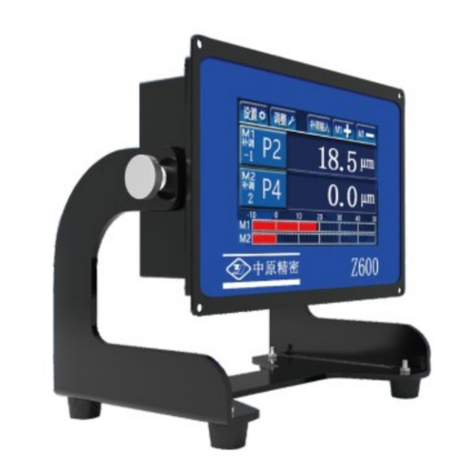
Sanmenxia ZX400 User manual

OPERATION MANUAL FOR GAUGE UNIT
ZX400
Sanmenxia ZhongyuanJingmiCo.,Ltd

In order to use the instrument safely, please follow the following instructions
DANGER
⚫Hazardous voltage can cause injury or death.
⚫Do NOT take out the covers unless there is qualified maintenance personnel.
⚫Please turn off the power switch and disconnect the power supply cable before taking
outcovers.
WARNINGS
⚫Hydraulic cylinder can cause injury. when used, driving gage head forward (downward)
or backward (upward) can cause injury. Please make sure the connected machine is not
operating before touching the hydraulic cylinder.
⚫Driven contacts of gage head can cause injury. Please make sure the connected machine is not
operating before touching the gage head contacts.
CAUTIONS
⚫Be sure not to operate this system when the gagging unit and/or control unit are in failure
(such as when the READY signal has gone off).
⚫Heavy load or strong force can deform the covers of control unit.
⚫Do not stand or step on the cover of the unit.
⚫For the sake of safety, the grounding wire of the power supply and all parts must be grounded,
and the outer shell of the controller is located at the screw above the output line
socket.
⚫Operation conditions must be:
1. Operation temperature 0~40 ℃
2. Humidity Less than 90%
3. Vibration Least possible ( less than 0.1G)
⚫Cleaning of the front panel:
1. The front panel is made from an acrylic resin pre-processed for non-glaring.
2. When the panel has smeared, dip a piece of soft cloth into liquid of neutral detergent or anti-
static agent, and wipe the panel with the cloth lightly.

3. Please do NOT use organic solvents such as alcohol to clean the device.
ABOUT CARRYING ABROAD
Due to the various local rules, please inform us before taking this device out of China. Our company
will not be responsible for any overseas accident if there is no declaration.

CONTENTS
1、Introduction ---------------------------------------------------------------1
2、Features---------------------------------------------------------------------2
3、Extension Function-------------------------------------------------------3
4、Interface --------------------------------------------------------------------4
4.1、Measuring Interface --------------------------------------------------5
4.2、Setting Interface -------------------------------------------------------6
4.3、Adjustment Interface--------------------------------------------------7
5、I/O Interface And Connection-------------------------------------------8
6、WSD-100 external receiving power signal table---------------------9
7、Method Of Use--------------------------------------------------------------10

- 1 -
1、Introduction
Z400 controller is based on the latest digital signal processing system,
using the latest control technology designed for grinding machine processing
on-line monitoring and control of the instrument.
This controller will be processed or after the size of the workpiece, with
electric sensor for measurement, if the use of air momentum meter for
measurement, it needs to be measured through the pneumatic probe and AE
converter. The measurement results are displayed on the LCD touch screen,
and the control signal is sent to the machine at the preset size. It has better
man-machine effect and more intuitive measurement status display. Easy to
operate, display more diversified.

- 2 -
2、Features
1) Intelligent control:All kinds of calculation and correction can be
carried out within the standard range, or the machining size
correction can be completed automatically under the control of the
machine tool. In the process or after the processing of the
measurement process, display a variety of measurement results and
judge the status of the point, while sending a signal to control the
movement of the machine.
2)Convenient and compact:Using 3.5-inch TFT touch screen LCD
display, embedded installation, low power design. Saving installation
space, energy saving and environmental protection.
3)Good human interface:The display interface is more intuitive and
clear,the display content is more rich and comprehensive, and the
operation is simpler and faster.

- 3 -
4)Good compatibility:In addition to the improvement of control,
display, operation, reliability and signal acquisition accuracy, the new
meter is easy to install and maintain.
5)Optimized design, the whole machine can meet the industrial
interference test.
3、Extension Functions:
1)External compensation:The measured data are compensated and
zeroed according to external input signals.
2)Memory selection: In order to measure the discontinuous surface can set
memory function, such as maximum memory.
3)BCD/ Binary: The digital interface to the machine tool.
4) 485 output.
5) Standard dual-channel sensor input.

- 4 -
4、Interface
Instructions:
ZX400 type active grinding measuring instrument is divided into three
function Windows, measuring, setting and adjusting.The system defaults into
the measurement module.
Click the button to enter the setting window.
Click the button to enter the adjustment window.
Click the button to manually enter the compensation value.
Click the button :Tonic + 。
Click the button :Tonic -。

- 5 -
4.1 Measuring the interface
Measurement interface
Window functions:The measured value of the measuring item is displayed,
adjusted and displayed in digital form.
Instruction:
:Displays the measured value of the measured item.
:Display signal points.
:Display compensation value.

- 6 -
4.2 Setting interface
If you need to change the setting parameters, click the number section,
and the keyboard pops up for setting.
Instruction:
P1 Signal points of rough grinding ;
P2 Signal points of fine grinding;
P3 Light grinding signal points;
P4 The signal point of retreating knife;

- 7 -
Signal point setting value: P1>P2>P3>P4;
SCUT The reverse cut value;
M Measurement expression:Can choose G1 ,G2 ,G1+G2 ,G1-G2;
S Filter way:Can choose 0, 1,2,3,4,5. (This option is a special
function and is only available when the user makes a special order.)
4.3 Adjustment interface
Instruction:
Display value: the value of the probe after processing;
Reset value: the compensation value of the probe by the system after resetting;
Multiplier: the probe amplification ratio can be set through the pop-up
keyboard; (The factory has been set, the standard value is 1, the user does not
need to adjust. Adjustment is required only when changing the length of
measuring device or rod.)
Reset button: press once to reset the displayed value, press again to restore the
original value;
The upper and lower measuring rods of the double-channel device are G2 and
G1 respectively.

- 8 -
5、I/O interface and connection
The I/O parameters:
Power supply: 24VDC±20% (>10W) 24V and 0V are respectively
connected to the red line and black line of the output line
Output signal: Relay 220V 5A
Input signal: Optocoupler 24V 3mA
Ground wire: the gray wire is connected to the ground wire of
the machine tool.
Number
I/0
Single item
Thread color
Remarks
1
OUT 1
P1
Orange
2
OUT 2
P2
Yellow
3
OUT 3
P3
Pink
4
OUT 4
P4
Blue
5
OUT 5
Receipt OK
Brown
6
OUT 6
*
Green
7
OUT 7
*
Light green
8
IN 1
*
Red/White
9
COM OUT
COMOUT
White
10
IN 2
Compensate +
Orange / White
11
IN 3
Compensate -
Blue / White
12
IN 4
Judgment begins
Purple / White
13
COM IN
COMIN
Purple
14
485 B
485B
Red/Black
15
485 A
485A
Orange/Black
16
GND
GND
Gray
17
18
5V
Yellow/Black
19
*
*
Black/White
20
*
*
Green/White
21
IN 0
*
Green/Black
22
24V 0
0V
Black
23
24
24V
24V
Red
25

- 9 -
6、WSD-100 External receiving power signal meter
WSD-100 External receiving power signal meter
Terminal
number
ZHD-1140BC(ZHS-173DC)
1
AC 220V
2
AC 0V
3
Red line
4
Yellow line
5
Black line COM
6
Retract input (switch signal)
7
Retract input (switch signal) COM

- 10 -
7、Method Of Use
7.1Adjustment method for standard double rod single chann
el sensor(ZHD-1070BC\1090BC\1080BC)
Enter the boot screen and press the button above the screen
or set the display value after compensation to 0.
Adjust the upper and lower contacts away from the measuring
surface.Click ,the system enters the adjustment window, the
interface displays G1, records the size of the display value, adjusts the
lower contact , makes the display value change to about half of the initial
value, locks the lower contact, and then continues to adjust the upper
contact ,Change the display value to about 0 (within ±30),lock the upper
contact. At this point,click ,the display value changes to 0, the
probe compensation value enters the reset value, and the adjustment is
over.Click ,enter the measurement interface.
7.2Standard Single Channel Sensor Adjustment Method (ZHS
series)

- 11 -
Enter the boot screen and press the button below the screen
or set the display value after compensation to 0.
Adjust the contact away from the measuring surface.Click ,the
system enters the adjustment window, the interface displays G1, records
the display value, adjusts the contact to make the display value change to
about 0 (the value is within ±30), and locks the contact. At this
point,click ,the display value becomes 0, the probe compensation
value enters the resetting value, and the adjustment ends.Click ,
enter the measurement interface.
7.3Standard dual-channel sensor adjustment method(ZHD、
ZHF series,except ZHD-1070BC\1090BC\1080BC)
Enter the boot screen and press the button below the screen
or set the display value after compensation to 0.
Adjust the contact away from the measuring surface.Click the
system enters the adjustment window, the interface displays G1, records
the display value, adjusts the lower contact to make the display value
change to about 0 (the value is within ±30), and locks the contact. At this
point,click ,the display value becomes 0, the probe compensation
value enters the resetting value, and the lower probe adjustment ends.
Display G2 on the interface, record the size of the display value, adjust the
upper contact to make the display value change to about 0 (within ±30),
and lock the upper contact. At this point, click ,the display value
becomes 0, the probe compensation value enters the resetting value, and
the adjustment ends. Click ,enter the measurement interface.

- 12 -
7.4Adjustment method for standard pneumatic sensors(ZHS-
AH series)
Enter the boot screen and press the button below the screen
or set the display value after compensation to 0. Click
,the system enters the adjustment window, the interface displays
G1, records the size of the display value, adjusts the throttle valve of the
sensor, makes the display value change to about 0 (the value is within ±
30), and locks. At this point, click ,the display value changes to 0,
the probe compensation value enters the resetting value, and the sensor
adjustment ends. Click ,enter the measurement interface.
7.5Multiplier adjustment method
During the use of the meter, the ratio should be adjusted when changing
the length of the measuring device or measuring rod.
Adjust the upper and lower contact away from the measuring surface.
Click ,the system enters the adjustment window, and the interface
displays G1. Adjust the lower contact so that the display value is about 0
(value within ±30).Click ,the display value is 0. Insert a 0.05mm
feeler between the contact and the measuring surface and record the display
value.Click ,Jump out of the keyboard, according to the actual value
and display value of the multiple relationship, directly input the
corresponding value. Repeat the process three times. The adjustment ends
when the displayed value is consistent with the actual value of the feeler. G2
is tuned the same as G1. Factory default setting is 1.00 (except ZHS-AH series).
The meter has been accurately adjusted according to the standard
when leaving the factory. There is no need to adjust the scaling rate
during normal use.

V1.4 20211108
Sanmenxia ZhongyuanJingmiCo.,Ltd
Address: east section of weiliu road, sanmenxia industrial park, henan,
China
Tel:0398-2751818 Fax:0398-2751819
Postcode:472000
http://www.zyjm.com
Table of contents
Other Sanmenxia Measuring Instrument manuals
Popular Measuring Instrument manuals by other brands

Fast Forward
Fast Forward EnergyCam Getting Started Tutorial

Triax
Triax MCT 048B user manual

Sentec
Sentec SDM Installation

PCB Piezotronics
PCB Piezotronics 8162-011A Installation and operating manual

YOKOGAWA
YOKOGAWA AQ2160-01 user manual

Badger Meter
Badger Meter Dynasonics DXN Series Firmware update manual