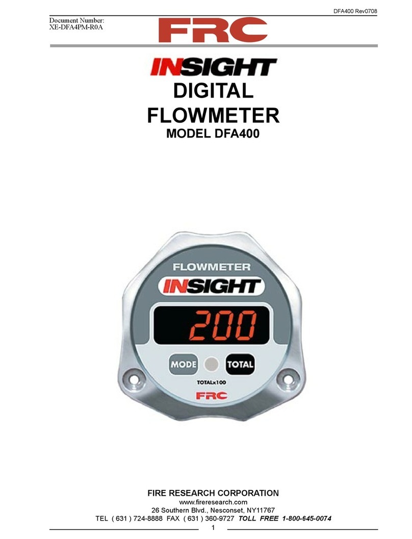
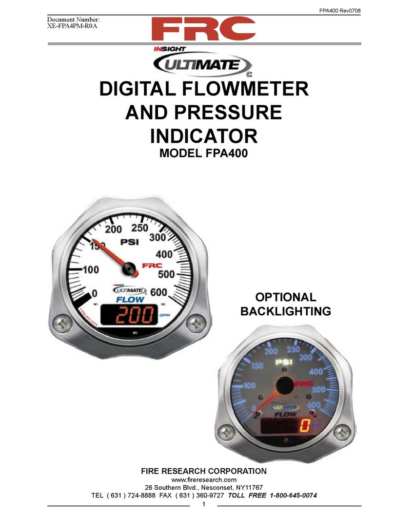
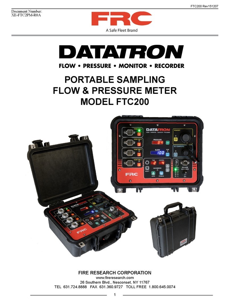
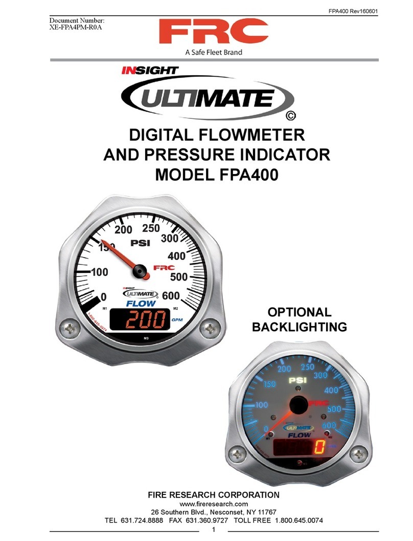
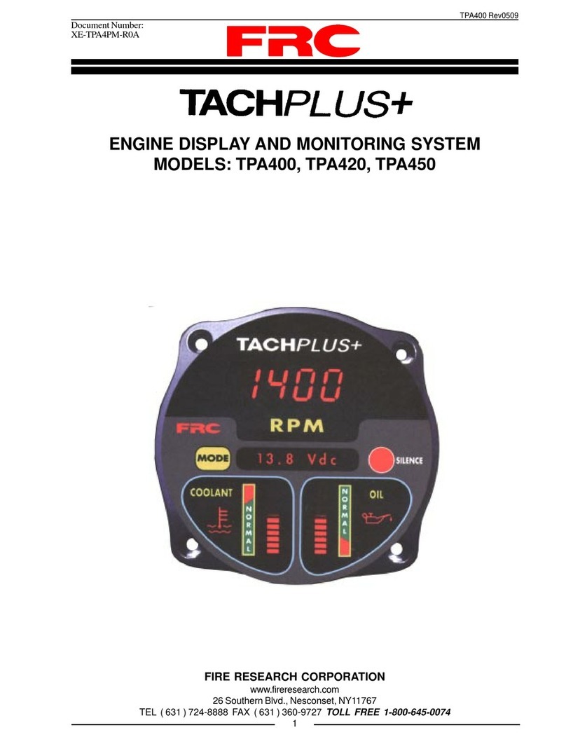
FRC Insight Ultimate Series User manual

FP4000 Rev0204
1
PRESSURE GAUGE AND
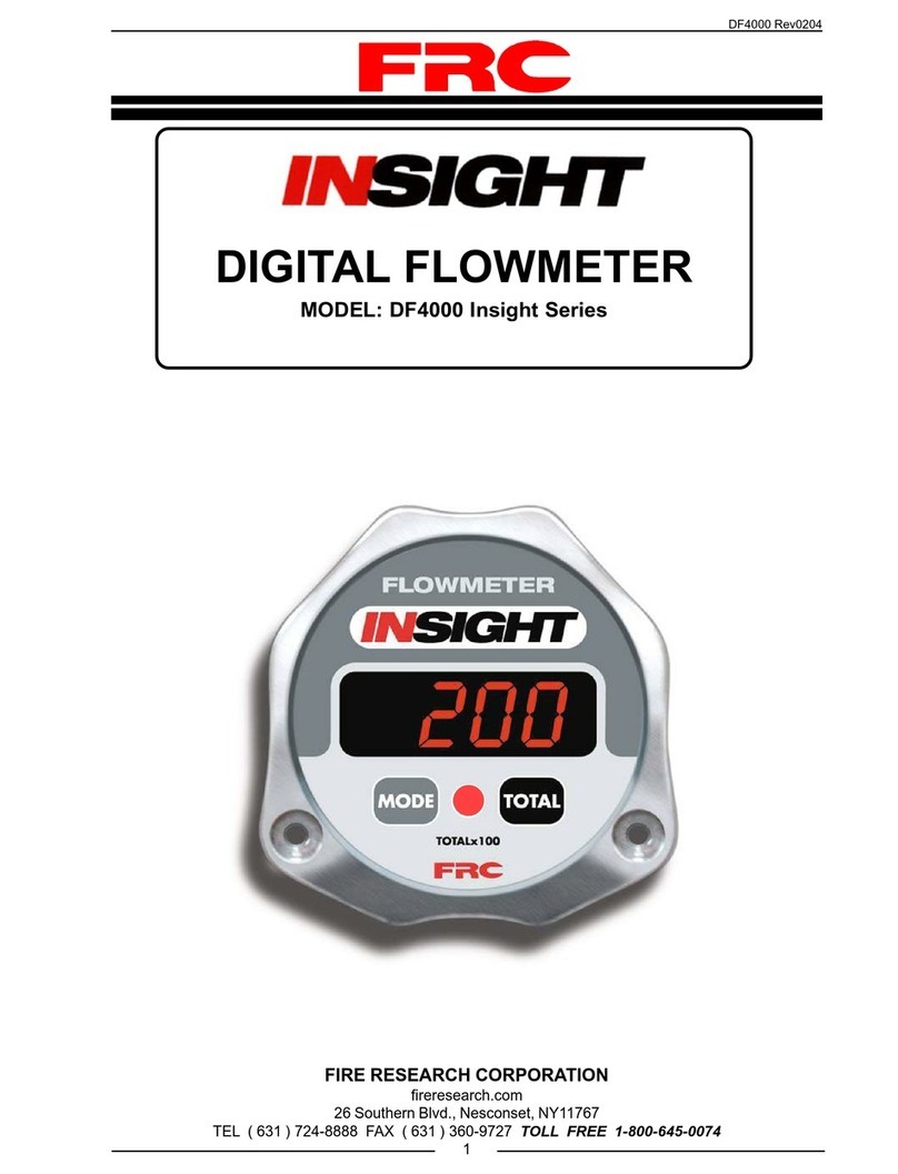
DIGITAL FLOWMETER
MODEL: FP4000 Insight Ultimate Series
FIRE RESEARCH CORPORATION
fireresearch.com
26 Southern Blvd., Nesconset, NY11767
TEL ( 631 ) 724-8888 FAX ( 631 ) 360-9727 TOLL FREE 1-800-645-0074

FP4000 Rev0204
2
CONTENTS
Table of Contents
CONTENTS ............................................................................................................... 2
List of Tables ......................................................................................................... 3
List of Figures........................................................................................................ 3
INTRODUCTION ...................................................................................................... 4
Overview ............................................................................................................... 4
Features.................................................................................................................. 4
Specifications ........................................................................................................ 5
GENERAL DESCRIPTION....................................................................................... 6
Components ........................................................................................................... 6
Controls and Indicators.......................................................................................... 7
INSTALLATION ....................................................................................................... 8
Install Display Module .......................................................................................... 8
Install Flow Sensor .............................................................................................. 10
Install Pressure Transducer.................................................................................. 16
Install External Totalizing Button Option ........................................................... 17
OPERATION............................................................................................................ 18
Datalink Interface ................................................................................................ 18
Program Features................................................................................................. 20
External Totalizing Button (Optional)................................................................. 20
PROGRAMMING.................................................................................................... 21
Magnet Sensors ................................................................................................... 21
Display Module Identification Mode .................................................................. 21
Program Access Mode......................................................................................... 23
Program Code Descriptions................................................................................. 24
CALIBRATION ....................................................................................................... 28
WIRING ................................................................................................................... 32
PARTS LIST ............................................................................................................ 34

FP4000 Rev0204
3
List of Tables
Table 1. Pressure Transducer Output Voltage ........................................................... 5
Table 2. Program Code Quick Reference ................................................................ 25
List of Figures
Figure 1. Controls and Indicators .............................................................................. 7
Figure 2. Display Module Mounting Dimensions ..................................................... 9
Figure 3. Flow Sensor Location Guidelines ............................................................ 11
Figure 4. Saddle Clamp Installation ........................................................................ 13
Figure 5. Weldment Installation .............................................................................. 15
Figure 6. Pressure Transducer ................................................................................. 16
Figure 7. Typical Datalink ....................................................................................... 19
Figure 8. Typical Programming Displays................................................................ 22
Figure 9. Primary Display Wiring ........................................................................... 32
Figure 10. Remote Display Wiring........................................................................... 33
Figure 11. Parts List................................................................................................. 34

FP4000 Rev0204
4
INTRODUCTION
Overview
The INSIGHT ULTIMATE pressure gauge and digital flowmeter combines a
traditional style electronic pressure gauge and a digital LED flow display into one
practical display module. The pressure gauge/flowmeter is able to communicate with
other display modules over the FRC datalink. This technology allows for remote
displays, the display of flow for multiple discharges (summing), and the totalization of
flow for multiple discharges (accumulation).
The pressure gauge is an electronically controlled analog display. During normal
operation pressure information is provided from a solid state pressure transducer or the
datalink interface. The pressure transducer provides an electrical signal to the input of
the display module. A microprocessor controls the needle movement to provide an
accurate and steady pressure display. Leakage and freeze-up problems common in
mechanical pressure gauges are eliminated.
The digital flowmeter is a 4-digit LED display. During normal operation flow rate
information is provided from a paddlewheel flow sensor or the datalink interface. This
information is processed and and shown on the digital display as flow rate.
There are two operator selectable modes; display module identification and program
access. The digital display is used to show stored data or operator inputs when a
selectable mode is accessed. In the display module identification mode the digital display
will show the module serial number, manufactured date, software revision, module
function, and ID number. In the program access mode the digital display will show
operator inputs, program options, and error codes. The operator selected modes are
accessed and inputs are made by using the three magnet sensors on the front of the
display module.
All controls and indicators are located on the front of the display module.
Features
Display Module Identification and Program Access Modes
Datalink Interface
Multiple Flow Rate Calibration Points
Pressure Scale Expands Between 100 and 250 PSI
High and Low Flow Warnings
NFPA Color Coded Bezel (Optional)
External Totalizing Button (Optional)
Flow Conditioner (Optional)
FP4000 Rev0204
5
Table 1. Pressure Transducer Output Voltage
Specifications
Display Module
Supply Voltage: 9 - 30 VDC
Supply Current: 1.0 Amp
Dimensions:
Height 4.4 Inches
Width 4.4 Inches
Depth 3.4 Inches
Datalink Protocol: J1939 CAN
Flow Sensor
Type: Paddlewheel with Brass Housing for Saddle Clamp
or Weldment Mount (Stainless Steel Housing
Optional)
Sensor Material: Acetal (Delrin) with Stainless Steel (316) Shaft
Excitation Voltage: 5 VDC
Pressure Transducer
Model Number: FP3100PT2, FP4000PT1 (Alternate Part)
Pressure Range: 0 - 600 PSI
Proof Pressure: 1200 PSI
Excitation Voltage: 5 VDC
Output Voltage: 0.5 - 4.75 VDC (Refer to Table 1)
PRESSURE
(PSI)
VOLTAGE
(VDC)
00.5
100 1.21
150 1.56
200 1.92
250 2.27
300 2.625

FP4000 Rev0204
6
GENERAL DESCRIPTION
Components
The INSIGHT ULTIMATE pressure gauge/flowmeter consists of the following
components:
Display Module
Pressure Transducer
Paddlewheel Flow Sensor and Sensor Housing Assembly
External Module Totalizing Button (Optional)
Cables
Display Module
The pressure gauge/flowmeter display module is waterproof and has dimensions
of 4.4 inches high by 4.4 inches wide by 3.4 inches deep. It is available with optional
NFPA color coded bezels. (The bezels are an intricate part of the display module and
must be factory installed.) All controls and indicators are located on the front of the
display module. (Refer to Controls and Indicators.)
Pressure Transducer
The pressure transducer provides an input signal to the display module that is
proportional to the discharge pressure. It is mounted on the downstream side of the
discharge valve. The electrical connector is waterproof and molded into the pressure
transducer housing.
Paddlewheel Flow Sensor
The flow sensor provides an input signal to the display module that is proportional
to the discharge flow rate. It is mounted in the discharge piping. Placement of the
sensor in the piping is critical to obtaining accurate flow rate information, refer to the
installation procedures for detailed information on mounting locations. The electrical
connector is waterproof and molded into the flow sensor housing.
External Totalizing Button (Optional)
The totalizing button allows the operator to display the total flow for a discharge.
When the button is pressed the number shown in the digital display times 100 will be
the total flow.
Cables
Interconnecting cables are provided. Refer to Wiring section.

FP4000 Rev0204
7
Controls and Indicators
All controls and indicators are located on the front of the display module. It contains
the pressure scale and indicating needle, a digital display, and the three magnet sensors.
(Refer to Figure 1.)
Pressure Display
The pressure scale is non-linear and is expanded between 100 and 250 PSI. This
provides for better visibility and more accurate readings in the normal operating range.
Digital Display
During normal operation this 4-digit LED display will indicate flow rate. When
the display module identification or program access modes are selected the digital
display shows module specific information, program codes, settings, and error codes.
See the Programming section for more information.
Magnet Sensors
The operator selected modes are accessed and inputs are made by using the three
magnet sensors M1, M2, and M3 located on the front of the display module. The M1
and M2 sensors are used to input data when in the program access mode. The M3
sensor is used to enter and exit these modes. See Programming section for more
information.
Magnet
The north pole of a small magnet is placed on the glass in close proximity to the
magnet sensor and then moved about 1 inch away to activate the sensor.
Figure 1. Controls and Indicators
M1 M2M3Digital
Display
Pressure
Scale
Pressure
Indicating
Needle
Optional Color
Coded Bezel

FP4000 Rev0204
8
INSTALLATION
The FP4000 display module, flow sensor, and pressure transducer are compatible
for use with any size piping.
Note: Plumbing systems are always unique and may cause small deviations
in the factory calibration. It is recommended that the calibration procedure
be performed after installation.
Install Display Module
The pressure gauge/flowmeter display modules are interchangeable. It is
recommended that the calibration be checked if modules are swapped.
Note: It is recommended to have the primary pressure gauge/flowmeter
mounted close to the associated discharge valve.
1. Measure and mark mounting location for display module panel cutout and
mounting screw holes. Make sure there is clearance behind the panel for the
display and cables before cutting holes. Refer to Figure 2 for layout and
dimensions.
2. Cut out a 3.75-inch diameter hole and drill two holes (clearance or tapped) for
10-32 mounting screws.
3. Place display module in position and secure with two screws.
4. Connect the display module cables and wires. (Refer to Wiring section.)

FP4000 Rev0204
9
Figure 2. Display Module Mounting Dimensions
3.74"
4.36"
.60"
4.34"
2.80" 10-32
Mounting
Screw
1.25"
3.75" Diameter Hole
Tap or Drill Clearence
Hole for 10-32 Screw
3.63"
Panel Cutout
C
L

FP4000 Rev0204
10
Install Flow Sensor
There are several ways to install FRC paddlewheel type flow sensors. Mounting
options include saddle clamps, weldments, pipe tees, and special adapters. Each mount
will meet particular plumbing requirements.
Flow sensors are interchangeable. It is recommended that the calibration be checked
if flow sensors are swapped.
The maximum pressure for a flow sensor installation is 600 PSI.
Flow Sensor Location
The location of the flow sensor in the plumbing system is critical. The flow of
water at and around the sensor must be laminar, or smooth, to ensure accurate flow
rate measurement. There must be enough straight pipe run before the flow sensor location
to allow the water stream to stabilize into a uniform flow. Guidelines for selecting flow
sensor locations are outlined in Figure 3.
When the sensor is mounted after an area in the plumbing that tends to increase
water stream turbulence (a valve, increase in pipe diameter, etc.), it is critical that steps
are taken to stabilize the flow.
•When a pipe is reduced in diameter the water stream tends to be squeezed
into a more uniform flow. This can be used to help stabilize flow when
there is not a sufficient pipe run up stream.
•FRC offers an optional flow conditioner that replaces the standard sensor
housing. It protrudes into the water stream at the sensor location and is
specially shaped to reduce local turbulence.
Linearizer Feature
FRC features a Linearizer function in the calibration programming. This function
should be used when the flow sensor is installed in a plumbing location where flow is
not linear. It corrects for nonlinear flow by allowing the display to be calibrated at
multiple flow rates (up to 10) to provide a more accurate flow rate display. (Refer to
Calibration section.)

FP4000 Rev0204
11
The preferred location for the mounting
of a flow sensor is on the top half of the
pipe. The best orientation is vertical. If
the sensor is mounted on the bottom of
the pipe, it may be susceptible to the
accumulation of dirt.
When mounting the sensor after an elbow
the length L must be at least 6 times the
pipe diameter.
When mounting the sensor before a valve
or an elbow the length L must be at least
equal to the pipe diameter.
When mounting the sensor after the pipe
diameter is reduced the length L must be
at least 2 times the pipe diameter.
When mounting the sensor after a valve
the length L must be at least 14 times the
pipe diameter.
Figure 3. Flow Sensor Location Guidelines
Best Orientation
L
L
L
L
After Elbow
L > 6 X PIPE DIA.
Before Valve or Elbow
L > 1 X PIPE DIA.
After Reduction
L > 2 X PIPE DIA.
After Valve
L > 14 X PIPE DIA.

FP4000 Rev0204
12
Saddle Clamp Installation
Note: Ensure that the mounting location meets the requirements for uniform
water flow. (Refer to Flow Sensor Location.)
Note: Ensure that there is enough room for the saddle clamp, sensor, and
connector to fit. (Refer to Figure 4.)
1. Drill and deburr a 1-11/16" to 1-3/4" diameter hole at mounting location.
2. Clean pipe surface in area where saddle clamp gasket will seal.
Note: The sensor housing is epoxied in the saddle clamp with the alignment
tab in the correct position and is not meant to be removed.
3. Place saddle clamp over hole with sensor housing centered.
4. Tighten saddle clamp nuts until the gasket makes a good tight seal.
5. Insert flow sensor into sensor housing. Align flat spot on sensor rim with
alignment tab and make sure o-ring is in groove.
Note: The retainer cap only needs to be hand tightened. There is an inside lip
that will stop the cap from turning when it makes contact with the alignment
tab. This provides the correct pressure to make the seal at the o-ring.
Make sure the flow sensor does not disengage from the alignment tab and
rotate.
6. Install retainer cap and hand tighten.
7. Connect cable from display module to flow sensor (the cable is color coded
blue). (Refer to Wiring section.)

FP4000 Rev0204
13
Figure 4. Saddle Clamp Installation
Note: These dimensions are
typical and are given to be used as
an aid in determining mounting
locations for flow sensors.
Note: Allow a minimum of 2
inches clearance at the sensor
top for removal/installation
of the connector.
Sensor
Housing
Paddlewheel
Flow Sensor
Retainer Cap
Saddle
Clamp
Alignment
Tab
O-Ring
Pipe Size Dimensions
(Sch 40) A B C
2 5.5 3.9 2.9
2.5 5.5 3.9 2.8
3 5.9 3.9 2.8
3.5 6.8 4.3 2.8
4 6.8 4.3 2.8
5 8 4.3 2.8
Measurements are in inches.
Note: When the retainer cap is
tightened make sure the sensor
rim flat spot does not disengage
from the alignment tab and
allow the flow sensor to rotate.
A
B
C

FP4000 Rev0204
14
Weldment Installation
Note: Ensure that the mounting location meets the requirements for uniform
water flow. (Refer to Flow Sensor Location.)
Note: Ensure that there is enough room for the weldment, sensor, and
connector to fit. (Refer to Figure 5.)
1. Drill and deburr a 1-11/16" to 1-3/4" diameter hole at mounting location.
2. Center weldment mount over hole and weld it to pipe. The weld must be
continuous around the fitting with no gaps or voids.
3. Screw sensor housing into weldment. Run it down far enough to make sure it
will go through the pipe freely then back it out.
Note: The paddlewheel sensor must be correctly aligned in the water stream.
The alignment tab is used to set the position of the sensor. Make sure that
the alignment tab is centered on the pipe centerline. (Refer to Figure 5.)
4. Set sensor housing to dimension A in Figure 5. Make sure the alignment tab is
centered on the pipe as shown (it can be on upstream or downstream side).
5. Screw on tru-seal locknut and tighten with a 2" wrench using light to medium
torque. Make sure that the sensor housing alignment tab remains centered and
the sensor housing does not rotate causing dimension A to change.
6. Insert flow sensor into sensor housing. Align flat spot on sensor rim with
alignment tab and make sure o-ring is in groove.
Note: The retainer cap only needs to be hand tightened. There is an inside lip
that will stop the cap from turning when it makes contact with the alignment
tab. This provides the correct pressure to make the seal at the o-ring.
Make sure the flow sensor does not disengage from the alignment tab and
rotate.
7. Install retainer cap and hand tighten.
8. Connect cable from display module to flow sensor (the cable is color coded
blue). (Refer to Wiring section.)

FP4000 Rev0204
15
Figure 5. Weldment Installation
Note: Allow a minimum of 2 inches
clearence at the sensor top for removal/
installation of the connector.
Note: These dimensions are
typical and are given to be
used as an aid in determining
mounting locations for flow
sensors.
Retainer Cap
Paddlewheel
Flow Sensor
Tru-Seal
Locknut
Sensor
Housing
Weldment
Alignment
Tab
O-Ring
Make sure that the alignment tab is
centered on the pipe centerline.
2.8"
2.5"
Note: When the retainer cap is
tightened make sure the sensor
rim flat spot does not disengage
from the alignment tab and
allow the flow sensor to rotate.
Pipe Size Dimension
(Sch 40) A
1.5 1.95 to 1.80
2 1.95 to 1.80
2.5 1.90 to 1.75
3 1.88 to 1.73
3.5 1.88 to 1.73
4 1.85 to 1.70
Measurements are in inches.
Alignment
Tab
A
Pipe
Centerline

FP4000 Rev0204
16
Caution: Do not use the main body
that houses the electronics to tighten
the transducer. Damage to the
transducer may occur.
Figure 6. Pressure Transducer
Install Pressure Transducer
The pressure transducer is mounted on the downstream side of the discharge valve.
Pressure transducers are interchangeable. It is recommended that the calibration
be checked if pressure transducers are swapped.
Note: Install the pressure transducer upright so water in the end of the pressure
transducer is able to drain back into the pipe.
1. Screw the transducer into a 1/4-18 NPT hole.
Caution: Do not use the main body that houses the electronics to tighten the
pressure transducer. Damage to the transducer may occur.
2. Tighten the transducer with a 9/16-inch (3/4 for alternate part) wrench on the
lower hex fitting.
3. Connect the pressure transducer cable from the display module to the pressure
transducer (the cable is color coded red). (Refer to Wiring section.)
1/4-18 NPT
1234567890
1234567890
1234567890
1234567890
1234567890
1234567890
1234567890
1234567890
1234567890
1234567890
1234567890
Lower Hex
Fitting
Supply
Voltage
5 VDC
Output
Signal
Ground
Main Body
1.04" 1.06"
1.02"
0.86"
0.80"
0.53"
0.78"
1.12"
FP3100PT2 FP4000PT1
Alternate Part

FP4000 Rev0204
17
Install External Totalizing Button Option
1. Mount a momentary on (SPST) switch near the display.
2. Connect a wire from one terminal of the switch to ground.
3. Connect a wire from the other terminal of the switch to pin 10 on the display
module connector. (Refer to Wiring section.)

FP4000 Rev0204
18
OPERATION
On power-up the pressure gauge/flowmeter will be in the normal operating mode.
Pressure and flow rate information from a transducer and a flow sensor or from the
datalink interface is processed and displayed. Operator input is necessary only when
using the totalizing function (with the optional external button) or accessing program
information.
Datalink Interface
The FRC datalink interface is standard on all pressure gauge/flowmeters and
provides a way of connecting multiple display modules on a shared data bus. The
FP4000 (pressure gauge/flowmeter) and DF4000 (digital flowmeter) series display
modules can operate as independent displays or they can be interconnected to provide
remote displays, the display of flow through multiple discharges (summing), and the
display of total flow for multiple discharges (accumulation). (Refer to Figure 7.)
Note: The FP4000 series can only be used as a primary or remote display
module.
Primary Display Module
Primary displays are programmed with the module function Pri. A primary display
receives input from the pressure transducer and flow sensor. When it is programmed
with Id 0 it will not output information on to the datalink. When it is programmed with
Id 1 to Id 99, it will provide information (via the datalink) to remote, summing, and
accumulator displays.
Remote Display Module
Remote displays are programmed with the module function SLA (slaved to a
primary). A remote display must be programmed with the same ID number as a primary
display. It will receive information for the display of pressure and flow rate from the
primary display over the datalink. All program code features are programmed
independently of the primary display. No calibration is necessary on a remote display.
Summing Display Module
Summing displays are programmed with the module function SU. A summing
display will show the actual flow rate for all primary displays on the datalink except
for those with Id 0. (Available on the DF4000 series only.)
Accumulator Display Module
Accumulator displays are programmed with the module function ACC. An
accumulator display will show total accumulated flow for all primary displays on the
datalink except for those with Id 0. The number shown in the display will be x 100
scale. (Available on the DF4000 series only.)

FP4000 Rev0204
19
Figure 7. Typical Datalink
REMOTE
PANEL(S)
PUMP
PANEL
FRC
Datalink
Function:
Pri
ID Number:
Id 1
Function:
Pri
ID Number:
Id 2
Function:
Pri
ID Number:
Id 3
Function:
Pri
ID Number:
Id 4
Function:
SLA
ID Number:
Id 1
Function:
SLA
ID Number:
Id 2
FLOWMETER
INSIGHT
Function:
SLA
ID Number:
Id 3
Function:
SLA
ID Number:
Id 4
FLOWMETER
INSIGHT
Function:
ACC
ID Number:
Id 0
FLOWMETER
INSIGHT
Function:
SU
ID Number:
Id 0
FLOWMETER
INSIGHT
Accumulatordisplay
redLEDwillbeonto
indicatex100scale.
Note: A primary display
programmed with Id 0 will not
output information to the datalink.
Note: A single display module can be used for
both summing and accumulation. Program it as a
summing display, when the TOTAL button is
pressed it will show total accumulated flow for all
primary displays on the datalink.

FP4000 Rev0204
20
Program Features
See Programming section for more detailed information.
High and Low Flow Warning (Codes 315 and 316)
When the flow rate is above the programmed high flow value a flashing -HI- will
show in the digital display. When the flow rate is below the programmed low flow
value a flashing -LO- will show in the digital display.
Flow Cutoff (Codes 318 or 319)
The digital display will show 0 when the flow rate goes below the programmed
flow cutoff value.
External Totalizing Button (Optional)
The totalizing button is used to perform two functions, display total flow for a
discharge and reset the totalized flow to 0 if the totalizer reset function is set to YES.
Display Total Flow
When the totalizing button is pressed and released the digital display will show the
total accumulated flow. (The flow will be x 100 the number shown in the display.)
Press and release the button again to show normal flow rate.
Reset Total Flow to 0
The totalizer reset function (code 317) has two program settings YES or no. (Refer
to Programming Section). To enable the reset function the program totalizer reset is set
to YES.
Totalized flow will reset and start from 0 when power is applied to the control
module. Flow total can be reset to 0 during operations by displaying the total flow and
then pressing and holding the totalizing button until the display shows 0.
This manual suits for next models
1
Table of contents
Other FRC Measuring Instrument manuals

FRC
FRC Air Sentinel AMA200 User manual

FRC
FRC InView 360 HD AVM User manual

FRC
FRC DFA400 User manual

FRC
FRC SeatMonitor SBA1GD User manual

FRC
FRC FPA400 User manual

FRC
FRC Insight Series User manual

FRC
FRC DFA400 User manual

FRC
FRC ThrottleXcel ELA100 User manual

FRC
FRC ThrottleXcel ELA100 User manual

FRC
FRC TACHPLUS+ TPA400 User manual
Popular Measuring Instrument manuals by other brands

Monroe Electronics
Monroe Electronics 257D Operator's manual

Perfect 10 Satellite Distributing
Perfect 10 Satellite Distributing Birdog manual

Fizoptika
Fizoptika VG910H Information guide

Vidicode
Vidicode Call Recorder Octo manual

HT Instruments
HT Instruments HT9019 user manual

Zircon
Zircon SuperScan M4 user manual