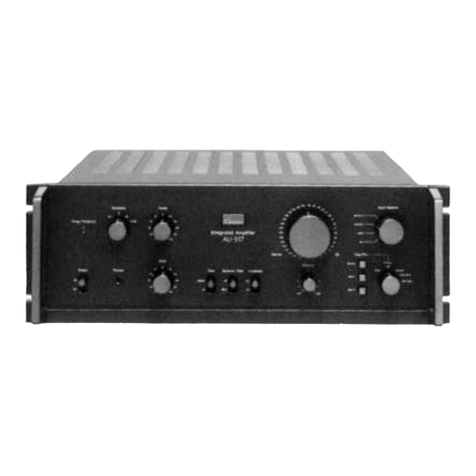
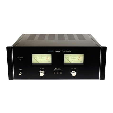
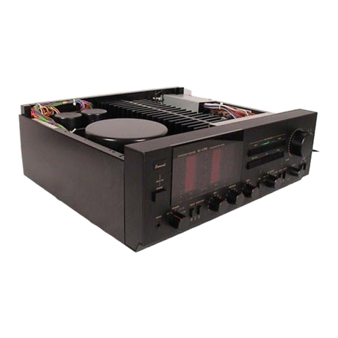
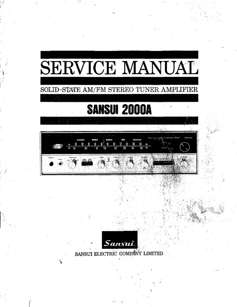
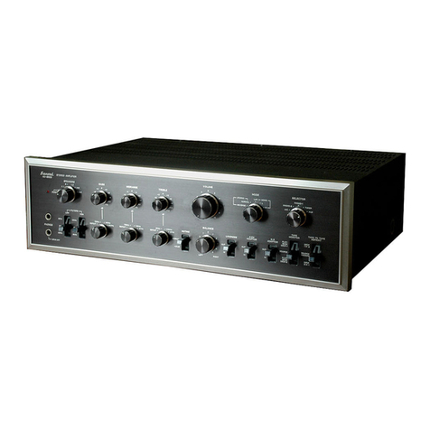
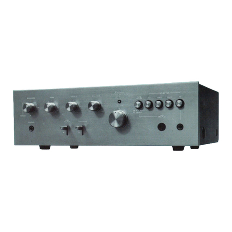
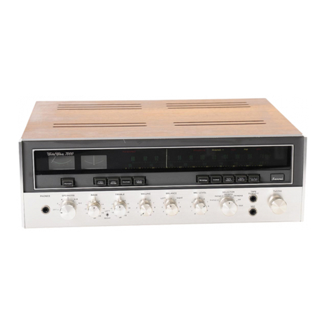
Sansui 2000X User manual

(aE
RUSTE
ee
SERVICE
MANUAL
SOLID-STATE
AM/FM
STEREO
TUNER
AMPLIFIER
SANSUI
ELECTRIC
COMPANY
LIMITED

CONTENTS
ce
a
GENERAL
TROUBLESHOOTING
CHART........006::::05
3,4
CUSTOM
MOUNTING:
cosese2
i
euctiansbarstauetaane
edie
5,6
DISASSEMBLY
PROCEDURE
\iisies
cnsansdavcceibicetama
tava
7
BLOCK
DEAGRAM
sired
ved
osrestosated
snags
eeenoneecuneas
8
ALIGNMENT
tea
E
PON
[os
pase
acetate
tate
eee
anaes
9,10
—FM
ALIGNMENT
PROCEDURE
....ceceeeeeeeeeeeeeeeeees
11
—FM
MULTIPLEX
ALIGNMENT
PROCEDURE
........
12
AM
ALIGNMENT
PRCCEDURE
....----ceceseeseeeeeeeees
13
JCURRENT
ADJUSTMENT
<2encunes
aiatnaveninieanes
14
OUTPUT
ADJUSTMENT
axcsuacawtavecudeeieauns
14
PRINTED
CIRCUIT
BOARDS
AND
PARTS
LIST
Pe
oceceg
aes
15,
16,
17, 18,
19, 20,
21,
22,
23,
24,
25,
26, 27,
28
OTHER
PARTS
AND
THEIR
POSITION
ON
CHASSIS

aoe
Saasiee
eect
aii
rrnseeenn
merge
0
aT
ae
pe
esi
EOE
a
se
suena
sae
s
SHE
H
oe
sacyena
yest
ie
alan
a
Settee

GENERAL
TROUBLESHOOTING
CHART
re
Te
SS
SS
If
the
amplifier
is
otherwise
operating
satisfactorily,
the
more
common
causes
of
trouble
may
generally
be
at-
tributed
to
the
following:
1.
Incorrect
connections
or
loose
terminal
contacts.
Check
the
speakers,
record
player,
tape
recorder,
antenna
and
line
cord.
2.
Improper
operation.
Before
operating
any
audio
com-
C
ponent,
be
sure
to
read
the
manufacturer’s
instructions.
3.
Improper
location
of
audio
components.
The
proper
positioning
of
components,
such
as
speakers
and
turn-
table,
is
vital
to
stereo.
4.
Defective
audio
components.
The
following
are
some
other
common
causes
of
mal-
function
and
what
to
do
about
them:
7
PROGRAM
SYMPTOM
PROBABLE
CAUSE
WHAT
TO
DO
AM,FM
or
MPX|
A.
Constant
or
intermit-
|
*
Discharge
or
oscillation
*
Attach
a
noise
limiter
to
the
electri-
reception
tent
noise
heard
at
caused
by
electrical
appli-
cal
appliance
causing
the
noise,
or
times
or
in
a
certain
ances,
such.
as
fluorescent
attach
it
to
the
amplifier’s
power
area
lamp,
TV
set,
D.C.
motor,
source
.
rectifier
or
oscillator
*
Install
an
outdoor
antenna
and
C
)
*
Natural
phenomena,
such
as
ground
the
amplifier
to
raise
the
we
atmospherics,
statics
or
signal-to-noise
ratio.
a
a
thunderbolts
*
Reverse
the
power
cord
plug-
*
Insufficient
antenna
input
receptacle
connections
due
to
ferroconcrete
wall!
x
If
.
:
:
the
noise
occurs
at
a
certain
or
done
distance
from
the
frequency,
attach
a
wave
trap
to
the
ANT.
input
i
F
Me)
ee
*
Keep
the
set
at
a
proper
distance
pp
from
other
electrical
appliances
B.
The
needle
of
the}
*
Receiver
is
located
in
a|
*
Place
the
set
to
receive
maximum
\
tuning
meter
does
not
weak
signal
area
signal
strength
move
sharply
C.
The
zero
point
of
the
|
*
Regional
difference
in
field
|
*
The
unit
is
not
at
fault
meter
diverges
much
intensity.
AM
reception
A.
Noise
heard
at
a|
*
Due
to
the
nature
of
AM]
*
Install
the
antenna
for
maximum
particular
time
of
a
broadcasts
antenna
efficiency.
See
‘“ANTEN-
day,
in
a
certain
area
NA”’
in
the
operating
instructions
or
over
part
of
dial
*
In
some
cases,
the
noise
can
be
eliminated
by
grounding
the
ampli-
fg
fier
or
reversing
.the
power
cord
ML
plug-receptacle
connections
B.
High-frequency
noise
*
Adjacent-channel
interfer-
|
*
Although
such
noise
cannot
be
ence
or
beat
interference
eliminated
by
the
amplifier,
it
is
ie
Ty
-eatctad.
Cloke:
to.
audio
advisable
to
adjust
the
TREBLE
postenn
control
from
midpoint
to
left
and
y
switch
on
the
HIGH
FILTER
*
Keep
the
TV
set
at
a
proper
distance
4
from
the
audio
system
FM
reception
A.
Noisy
*
Poor
noise
limiter
effect
or
|
*
Install
the
antenna
(supplied)
for
too
low
SN
ratio
due
to
maximum
signal
strength
&
insuficrenbantentaaput
*
If
this
does
not
prove
effective,
use
an
outdoor
antenna
designed
Note:
FM
reception
is
affected
considerably
by
exclusively
for
FM.
When
you
use
transmission
conditions
of
stations:
power
and
a
TV
antenna
for
both
TV
and
FM
antenna
efficiency.
Asa
result,
you
may
receive
with
a
splitter,
make
sure
TV
recep-
one
station
quite
well
while
receiving
another
tion
is
not
affected
station
poorly
*
An
excessively
long
antenna
may
f
cause
noise
(
:
oe
a
SS
eee
|

PROGRAM
FM
reception
SYMPTOM
B.
A
series
of
pops
is
PROBABLE
CAUSE
Ignition
noise
caused
by
WHAT
TO
DO
*
Install
the
antenna
and
its
lead-in
(cont’d)
heard
an
automobile
engine
wire
in
proper
distance
from
the
road
or
raise
the
antenna
input
as
described
above
C.
Tuning
noise
between
|
*
This
results
from
thenature.|
*
Turn
the
muting
on.
stations
of
the
FM
reception.
As
the
station
signal
becomes
weak,
the
noise
limiter
effect
is
decreased,
and
the
amplifi-
cation
of
the
limiter,
in
turn,
is
enlarged,
generating
a
noise
FM-MPX
A.
Noise
heard
during
|
*
Weaker
signal
because
the
|
*
Install
the
antenna
for
maximum
reception
FM-MPX
_
reception
service
area
of
the
FM-
antenna
input
while
not
heard
during
FM
mono
reception
MPX
broadcast
is
only
half
that
of
the
FM
mono
broad-
cast
B.
Clearness
of
channel
separation
isdecreased
during
reception
Excess
heat
C.
The
stereo
indicator
blinks
on
and
off
D.
The
stereo
indicator
blinks
on
and
off
even
though
stereo
station
is
not
received
Interference
Interference
*
Switch
on
the
HIGH
FILTER
and/or
turn
the
TREBLE
control
from
mid-
point,
left
*
Circulation
of
air
is
important
to
the
amplifier.
Be
sure
that
air
is
flowing
under
the
amplifier
*
The
indicator
is
not
at
fault.
Adjust
VRaor
*
The
indicator
is
not
at
fault.
Adjust
VRao1
,
Record
playing
or
tape
playback
A.
Hum
or
howling
Record
player
placed
direct-
ly
on
speaker
Wire
other
than
shielded
wire
used
Loose
terminal
contact
Shielded
wire
too
close
to
line
cord,
fluorescent
lamp
or
other
electrical
appli-
ances
Nearby
amateur
radio
sta-
tion
or
TV
_
transmission
antenna
*
Place
a
cushion
between
the
player
and
the
speaker
box
or
place
them
away
from
each
other
*
The
connecting
shielded
wire
should
be
as
short
as
possible
*
Switch
on
the
LOW
FILTER
and
turn
the
BASS
control
from
midpoint
to
left
*
Consult
the
nearest
Radio
Regulatory
Bureau
B.
Surface
noise
*
*#
&
&
*
Worn
or
old
record
Worn
stylus
Stylus
dusty
Improper
stylus
pressure
Worn
playback
head
*
Switch
on
the
HIGH
FILTER
and
turn
the
TREBLE
control
from
mid-
point
to
left
*
Clean
or
replace
the
stylus
*
Replace
the
playback
head.
All
stereo
programs
BALANCE
control
is
not
at
midpoint
when
equal
sound
comes
from
left
and
right
channels
It
is
important
to
adjust
for
equal
sound
from
both
channels.
It
should
not
always
be
set
to
the
mid-
point
*
Set
the
MONO
switch
to
MONO
and
then
set
the
BALANCE
control
to
a
position
where
equal
sound
comes
from
both
channels

CUSTOM
MOUNTING
aa
How
to
install
the
amplifier
in
a
wooden
cabinet
1.
Make
a
cabinet
cutout
of
432mm
or
17”
in
width
and
117mm
or
4°°/64”
in
height.
:
2.
Place
two
square
pieces
of
wood
(20
X
20x
240mm
or
25150”
X
8/50”
X
92°/,,”)
for
supporting
the
amplifier
in
the
bottom
board
of
the
cabinet.
3.
Cut
two
holes
for
attachment
bolts
in
the
bottom
board
of
the
cabinet.
4,
Remove
the
amplifier
from
the
wood
case
(Refer
to
the
section
entitled
“DISASSEMBLY
PROCEDURE”).
5.
Place
the
amplifier
in
position
through
the
cabinet
cutout.
6.
Make
sure
the
amplifier
is
in
position,
then
put
the
washers
in
butterfly
bolts
(4X
40mm)
and
fix
the
amplifier
to
the
cabinet
with
the
butterfly
bolts,
Note:
When
the
amplifier
is
built
into
the
custom
cabinet,
the
wood
case
:
assembly
including
screws
and
washers
is
not
used.
Retain
it
for
future
uses
Ueto
ais
ae
ae

AMO
17
Fe
Width
of
front
panel
board
20
4,35”
ol
if
a
reenraraet
beigebig
head
AB
latelned
os
e
ae
ae
Spe
ite
A387
|
:
#
Front
width
of
cabinet
window
st
oo =a
ee
os
=
2
3s
j
Cees
|
POPOV
AE
VOOPL
PET
EL
ATL
OE
T
External
dimension
of
panel
z
=
ees
LOIS
SiON
ee
H
8
D
|
£
8
External
dimension
of
cabinet
can
22
pe
a
aU
ys
oD
alt
alt
®
c
oko
wko
S
peers
eT
Sears
at
ta
Se
ef.
wt
no
oF
Ne
~_
7)
Bo
D
‘D
pei
pag
aes
ite,
=
iol
a
tad
320%,
1233”
—__-------—-
20%,"
8
”
rs,
S
oe
K-7
2
‘
if
i
|
|
ree
als
Lk
i
os
+
|
x
€
¥
YO)
2
=
=
le
--
2.
re
eee
ne
aaa
(cd
_
=
7
Pd
a
Amplifier
fixing
buterfly
bolts
!
=
L.
Cj
|
Lees,
eee
Les
5
|
a
s
okt
Washers
>a
*
_
10d
m4,
2”
&
—
E
X
=
13)”
2407
98
a
350%
13
BB
“
+
#
—

DISASSEMBLY
PROCEDURE
=
——.
ee
REMOVING
THE
WOOD
CASE
bad
e=-0@——\_/
REMOVING
THE
FRONT
PANEL
AND
BOTTOM
PLATE
DIAL
MECHANISM

BLOCK
DIAGRAM
FM
PACK
oe
(NO100}
if
FETio1
TRiez
ii
)
Lio
02
3
iol
af
FM
ANTENNA
|
38
||
3002
~T
Le
75.2000
||
&
AMP
HIGH
FREQUENCY
a
FREQUENCY
107
MHz
FM
_INTER
(F-1214-1)
(No.200)
T204
10.7MHZ
T203
10.7MHZ
oad
Teo2
1C204
$+—+-2C
OUT
DISCRIMI
~NATOR
i
Le.
AM
= 2
__
=
__
le
eateries
=
ANTENNA
{
455kHz
455KH2
A
|
HIGH
FREQUENCY
AMP
MIXER
=
IF
AMP
©
AMPS
Qe
4
ow
a
EEE
-
5
|
MUTING
|
i
career
17>
peated
|
|
TR302
TR304
&
DETECTOR]
|
1
j
|
T303
T7304
T305
+
|
!
!
T302
=
|
!
|
|
OSC
COIL
METER
Le
ieee
mS
eee
i
el
oa
|
Pee
here
ee
ee
ia
ra
|
COMPOSITE
19kHz
|
{SIGNAL
AMP
AMP
|
|
2C
AAG
I9kH2
TUNING
|
DEEMPHASIS
2
~-MPX
=
oy
NOISE
CANCELER
|
|
38kH2
FILTER
¢
|
|
ea
8
(F-1224)
|
[
}
|
Po
I
MYVTIRPLER
STEREO
(F-1190)
(NO,400)
!
|
|
ne
NOISE
AMP
|
ERASER
(K
avis
i
Daoe
ai
STEREO
!
TR405
TRa06
|
TRao
INDICATOR
PLois
|
i
Ng
STEREO
INDICATOR
|
-
--
Sees
meas
TAPE
MON.
|
TONE
CONTROL
|.
2!
Mire
Ue
Rs
oe
ee
y
;
LOW
FREQUENCY
AMP
Hon)
‘
TR701
TR7o2
if
3
TRaor
TReo2
TReo3
{
3
=
C}
PHONO
2
1
|
#®)
)
Pe
gh
@
<
be
~
o
°
Baars
fl
TR6O1
TREO2
J
Uh
TF
I
Laan!
TRIOS
i
|
\
a
|
is
-
I
Ps
x
|
©
a
V
N
\
‘fil
ce
1
¢
1
4
&
FM
AUTO
o|
BLOCK
(X)
of!
itl
Lior
ie
5
eH”
Aux
o|
ra
{
at
|
|
|
TONE
|
a
x
i
|
5
3
lo
be
.
‘at
fs!
CONTROL
|
1
a
‘5
7
elite)
|
5 w
E
EQUALIZER
SB:
Hesjuy
wl
S),
wl
al
Bla
(F-12224)
|
ty
5
gl
Q
Zz
Sig}
gS)
S15)
oa
)
a
ino.
700)
!
DRIVER
AMP
|
oe
2
FA
Bit
AMP
wy)
isiat
Susi
|
SL
NP
!
(F+1180)
ae
ls
ily
(F-12583)
|
Big)
(igiGl
"sl
El
a
1
|
ina
boo)
5
4m
Oe
B,
1
.ANO.600)
|
(S|er
eu
|
Vy
Wt
|
a
i
Pe
|
e
\
l
!
TReo:
|
TReis
3
K
9
:
TAPE
REC
‘Ay
aE
1S
13
2!
TReio0
|
TRei¢
J
\
I
oe
I
-—4
t
TR706
jus
2]
TReoe
TReo7
TReos
Pr!
/
ao
!
L
\
eg
/
=
PHONOZ:
/
ai
PHONOTO
I
aa
5
AMO
TReos
—
TReo4a
DIN
TR704
TR705
i
ee
5
i
NE
TONE
CONTROL
oy
ies
{
BLOCK
are
won,
b-—
ee
4
H
AUXo
{LOW
FREQUENCY
AMP
fae
PRE
AMP
peeeepazen
Aaa
BLOCK
I
ae
6
Tilt
eves
Ae
ORIVER
AMP
AC
100V
1
Door
a
|
‘itce
110V
Tl
Vi7V
POWER
il
Bayi
CIRCUIT
|
Dooz
TRoo:
|
(NO.000
)
j
230V
|
RECTIFIER
ell
240V
}
CIRCUIT
tRIPPLEZ20o
Z2Dooz
|
eOOY
KE-MI9Z)(no.
000)
|
FILTER
CIRCUIT
|
50~60Hz
((F-11954)(no.000)
|

TEST
POINTS
3B
3A
L105
Lio2
Loi
L103
Lio4
2A
TP201
TP202
TP204
TP203
2C

ean
eet
ee
S
PE
21
4
ea
MI
=
-
S
‘
Ss
A
z
|
Pee
ee
Z
Coo
e
:
ba
C
Be
e
ee
bs
&
y
By
ae
ss
a
ay
.
s
4G
4H
4I
4J
4B
4k
4A
—-
10
——

ALIGNMENT
FM
ALIGNMENT
PROCEDURE
NOTE:
To
align,
set
the
signal
generator
level
to
minimum.
Turn
tuning
gang
fully.
Center
carrier
wave.
Set
pointer
at
reference
mark.
DIAL
ADJUST
STEP
ALIGN.
GENERATOR
FEED
SIGNAL
|
CONNECT
SETTING
ADJUST
FOR
1.
IF
10.7
MHz
Sweep
signal
to
|
Oscilloscope
to
Top
and
bottom
|
Best
IF.
Trans-
+200
kHz
TPio:
via
the
TPeot,
202
and
2o3
sides
of
T21,
202,
|
wave
form
former
10pF
ceramic
via
the
10pF
208
capacitor
ceramic
capacitor
with
probe
“2.
Discrimi-
10.7
MHz
Sweep
signal
to
|
Oscilloscope
to
FM.
S
curve
nator
+200
kHz
TPio1
via
the
2
Discriminator
10pF
ceramic
transformer
capacitor
Toos
top
and
bottom
sides
3.
0.S.C
90
MHz
To
antenna
Oscilloscope
90
MHz
O.S.C.
coil
Maximum
400
Hz
100%
terminals
and
V.T.V.M.
Lios
Modulation
to
output
load
4.
0.8.C
106
MHz
To
antenna
Oscilloscope
106
MHz
O.S.C.
trimmer
|
Maximum
400
Hz
100%
terminals
and
V.T.V.M.
TCyos
Modulation
to
output
load
5.
Reiterate
3
and
4.
6.
High-
90
MHz
To
antenna
Oscilloscope
90
MHz
Antenna
coil
Maximum
frequency
|
400Hz
100%
terminals
and
V.T.V.M.
Lio1,
Liog
and
Amp.
Modulation
to
output
load
108
Circuit
Te
High-
106
MHz
To
antenna
Oscilloscope
106
MHz
Trimmer
TCyo;,
|
Maximum
frequency
|
400Hz
100%
terminals
and
V.T.V.M.
TCiog
and
TCio4
Amp.
Modulation
to
output
load
Circuit
8.
Reiterate
6
and
7.
FM
IF
WAVE
FORM
FM
DISCRIMINATOR
WAVE
FORM
~200
KHz
=
KHz
-100
10.7
+100
+200
MHz.
KHz
KHz
——
|
+
—200
100
KHz
KHz
497)
MHz
=
+100
+200
KHz
KHz

FM
MULTIPLEX
ALIGNMENT
PROCEDURE
1.
Do
not
attempt
to
align
the
Multiplex
Circuit
unless
the
following
equipments
are
available:
e.
FM
Signal
Generator
a.
Multiplex
Stereo
Generator
STEP
ALIGN.
67
kHz
Trap
71
kHz
Trap
19
kHz
Transformer
19
kHz
Transformer
38
kHz
Transformer
38
kHz
Transformer
and
Separation
VR
GENERATOR
67
kHz
Audio
Signal
71
kHz
Audio
Signal
FM
Signal
Gen.
Modulated
30%
by
STEREO
Gen.
sub-channel
FM
Signal
Gen.
Modulated
30%
by
STEREO
Gen.
sub-channel
FM
Signal
Gen.
Modulated
30%
by
STEREO
Gen.
sub-channel
FM
Signal
Gen.
Modulated
30%
by
STEREO
Signal
Gen,
channel-L
FEED
SIGNAL
TO
TPya
or
2C
TPya
or
2C
Antenna
terminals
Tune
to
signal
Antenna
terminals
Tune
to
signal
Antenna
terminals
Tune
to
signal
Antenna
terminals
Tune
to
signal
ee
|e
b.
Oscilloscope
c.
AC.
V.T.V.M.
d.
Audio
Oscillator
TEST
EQUIPMENT
(S)
V.T.V.M.
at
4]
V.T.V.M.
at
4]
V.T.V.M.
and
Oscilloscope
at
AK
V.T.V.M.
and
Oscilloscope
at
4J
V.T.V.M.
and
Oscilloscope
at
4H
V.T.V.M.
and
Oscilloscope
at
output
load,
(channel-R)
ADJUST
Lizo3
Ligon
Taos
Toe
Tos
Tyoe
or
Taos
within
4
turn
and
Separation
VR(VReo1)
,
ADJUST
FOR
Minimum
Minimum
Maximum
Maximum
Maximum
Minimum,
(Channel-R)

ALIGNMENT
AM
ALIGNMENT
PROCEDURE
NOTE:
To
align,
set
the
signal
generator
level
to
minimum.
FEED
|
DIAL
STEP
ALIGN.
|
GENERATOR
SIGNAL
TO
TEST
EQUIPMENTS
|
SETTING
ADJUST
ADJUST
FOR
1.
LF.
455
kHz
Antenna
|
Oscilloscope
Top
and
bottom
Best
L.F.
Transfor-
+30 kHz
terminals
{|
and
V.T.V.M.
at
sides
from
the
1st
|
wave
form
mer
|
Sweep-generator
|
3G
|
LF.T.
(Toa)
to
i.
|
the
3rd
i
1)
Se
(308)
2.
O.S.C.
AM-generator
Antenna
Oscilloscope
535kHz
|
O.S.C.
Coil
Taos
Maximum
535
kHz
terminals
and
V.T.V.M.
at
|
400
Hz
30%
output
load
Modulation
|
3.
O0.S.C.
|
AM-generator
Antenna
Oscilloscope
1600kHz
|
O.S.C.
Trimmer
|
Maximum
1600
kHz
terminals
and
V.T.V.M.
at
|
TCeos
|
400.Hz
30%
output
load
Modulation
|
|
|
|
4.
Reiterate
| |
2
and
3
|
i
5.
RF
amp.
|
AM-generator
Antenna
Oscilloscope
|
600kHz
|
RF
transformer
Maximum
600
kHz
terminals
and
V.T.V.M.
at
|
Tso1
400
Hz
30%
output
load
Modulation
|
6.
Antenna
AM-generator
Antenna
Oscilloscope
600kHz
|
Ferrite
bar
Maximum
circuit
600
kHz
terminals
and
V.T.V.M.
at
Antenna
400
Hz
30%
output
load
Ts06
Modulation
ae
RF
amp.
AM-generator
Antenna
|
Oscilloscope
1400kHz
|
RF
Trimmer
Maximum
1400
kHz
terminals
and
V.T.V.M.
at
TCeoe
400
Hz
30%
output
load
Modulation
8.
Antenna
AM-generator
|
Antenna
Oscilloscope
1400kHz
|
Antenna
Maximum
circuit
1400
kHz
terminals
and
V.T.V.M.
at
circuit
400
Hz
30%
output
load
Trimmer
TCgo3
Modulation
9.
Reiterate
|
5.6.7.8.
|
ee
(eee
AM
IF
WAVE
FORM
+
=
kHz
—IOkHz
455
.+10kHz
|

STEP
SETTING
OF
AMMETER
(TESTER)
100mA
range.
100mA
range.
WAHT
TO DO
Remove
F
9;
and
Foe
Set
VReoz
and
VReo4
to
minimum.
Set
VRioe
and
VRuiog
(VOLUME)
to
mini-
mum.
Push
the
switch
ON.
POWER
Connect
the
ammeter
to
Feo;
as
illustrated
in
Fig.
1.
Turn
VRgo,
_
clock-
wise
and
adjust
cur-
rent
to
15
to
l0mA
at
room
temperature
of
25°C
or
less
or
to
20
to
15mA
at
25°C
or
more.
|
Push
the
POWER
|
switch
OFF
and
at-
tach
Fo;
in
place.
Push
the
POWER
switch
ON
and
con-
nect
the
ammeter
to
Foz
as
illustrated
in
Fig.
1.
Turn
VRgoz
clock-
wise
and
adjust
cur-
rent
to
15to10mA
at
25°C
or
less
or
to
20
to
15mA
at
25°C
or
more.
Attach
Fgoe
in
place.
1.
CURRENT
ADJUSTMENT
NOTE
Use
an
am-
meter
having
100
or
50mA
range.
Be
sure
to
switch
on
lst
and
then
con-
nect
the
am-
meter.
Feoi
TO
AMMETER
AMMETER
more
than
100mA
range
BACK
PANEL
<Fig,
>
QUICK-ACTING
FUSE
HOLDER
STEP
A
4a
Ss
WHAT
TO
DO
Adjust
the
volume
control
to
minimum.
Set
an
oscillator
to
1,000Hz
and
connect
it
to
the
LEFT
AUX
|
input.
Set
the
SELECTOR
switch
to
AUX.
Connect
a
8
or
16-
ohm
load
resistor
hav-
ing
capacitor
of
more
than
50
watts
to
the
LEFT
SPEAKER
output.
Connect
an
oscillo-
scope
to
the
SPEAK-
ER
terminal.
Push
the
POWER
switch
on
and
ad-
vance
the
volume
little
by
little.
Check
the
output
at
the
terminal
by
means
of
the
oscilloscope.
Adjust
VRgo;
so
that
the
fronts
of
sine
wave
are
clipped
sim-
ultaneously
Adjust
the
right
chan-
nel
as
above.
In
Step
7,
adjust
VRaps.
2.
OUTPUT
ADJUSTMENT
NOTE
The
oscillator
used
should
have
the
oscil-
lation
frequency
of
20
to
20,000Hz
and
the
output
voltage
of
more
than
200mV.
Set
other
controls
and
switches
as
follows:
BALANCE
to
CENTER
TAPE
MON.to
OFF
MODE
to
STEREO
TONE
to
CENTER
Others
to
OFF

PRINTED
CIRCUIT
BOARDS
AND
PARTS
LIST
W:
Parts
No.
X:
Parts
Name
Y:Stock
No.
Z:
Position
of
Parts
ce
ONE
COMBE
oe
Ww
x
Y
Zz
Ww
»
4
Y
Z
R701
kA
0101102
|
2c
C717
0.22
uF
+10%
50
V
MC.
|
0601228
|
2D
R702
47k
0
0101473
|
1D
C7is
|
33
uF
6.3V
EC.
0510330
|
1,2C
R703
68kO,
0101683
|
1D
C719
|
120pF
=10%
50
V
CC.
0660121
|
1C
R704
100kQ,
0101104
1D
C720
33
uF
16
V
EC.
0512330
;
1C
R705
1k
0101102
|
1¢,
D
Cra
1
pF
50
VEC.
|
05151091
1,2C
R706
270k
0101274
|
1C,
D
C722
|
(0.01
Suk
0601157
|
1C
|
|
R707
3.9k0
0101392}
1C,D
C723
0.0015
uF
+10%
50
V
MC.
0601156
|
2B
R708
B.2k0
0101822
|
ic
C724
0.04uF
0601408
|
2A
R709
2.7kO,
0101272
1c
C725
0.04
uF
0601408
|
2A
R710
6.8k
0101682
|
28
C726
|
10
uF
50
V
EC.
|
0515100
|
1,28
R711
6.8kO
0101682
|
98
C77
100pF
10%
SOV
CC.
|
0660101
|
18
R712
10kQ
0101103
|
1,28
C728
47
pF
6.3V
EC.
|
0510470
|
1,28
R713
10kO
0101103
|
1A
C729
1yeF
50
V
EC.
0515109
|
1A
R714
22k.
010122317,
*
R715
150kQ,
0101154
|
2A
R701
}
1010400
|
2D
Rei
aaa
01011841
12
VR705
250k.
M,
N
Balance
Control
1010400
|
20
R717
390k
0101394
|
18
VR702
1010200
2c
pois
ers
0101861
|
1A
VR706
250kQ.
B
Volume
Control
1010200
|
oc
R719
5.6kO
0101562
|
14
VR703
1020040
|
28
0
ean
rook
»
10%
MW
CR.
o1oit04
|
44
VRv07
100kQ
B
Treble
Control
1020040
|
28
R721
1kO
0101102
|
ap
WR704
1010040
|
2A
100kQ
B
Bass
Control
R722
ATK
0101473
|
1p
VR708
Cesare
1010040
|
2A
R723
68k
0101683
|
2¢,
D
R724
100kQ
0101104
|
1p
TR701
|
28C458
LG(C)
ps0se
tt
0
R725
1kQ
0101102
|
4¢
Usk
25C458
LG(B)
Ssaeat
-
R726
270kQ
0101274
|}
9c
,
i
28C458
LG(C)
O3083
R727
3.9kO,
0101392
|
1¢.
p
iu
pated
t
Ae
:
:
TR705
25C458
LG(B)
0305310
|
1C
ae
sles
Orat
eee
Fe
TR70s
|
28C458
LG(C)
0305311
|
18
R729
2.7k0.
0101272
|
1¢
a
|
5
R730
68k.
0101682
|
28
R731
6.8kO,
0101682
|
2B
R732
10kQ
0101103
|
2A,
B
R733
10kQO
0101103
|
2A
R734
22k0
0101223
|
1A
R735
150kQ,
0101154
|
2A
R736
150k
0101154
|
2B,C
R737
390k0,
0101394
|
1B
R738
5602)
0101561}
1B
R739
§.6kO,
0101562}
18
R740
100k
0101104
|
1A
C701
Star
feet
Ae
0601107
|
2¢
Abbreviations
C702
O.22nF
J
~
;
0601228
|
1,2D
CR:
Carbon
Resistor
C703
220
uF
25
V
EC.
0513221
|
1,20
SR:
Solid
Resistor
C704
33
uF
6.3
V
EC.
0510330
|
1¢
j
C708
120pF
+10%
50
V
CC.
0660121}
1¢
CeR:
Cement
Resistor
C706
|
33
uF
16
V
EC.
0512330
|
1C
McC:
Mylar
Capacitor
hes
lee
So
SEs
aie
Bes
EC:
Electrolytic
Capacitor
C708
0.015
4F
0601157
|
1c
es
C709
0.0015
pF
0601156
|
2B
AEC:
Aluminium
Electrolytic
Capacitor
Cri0
0.04ur(
10%
50.
V
MC.
|
9601407
|
2A
MiC:
Mica
Capacitor
cri
0.04
uF
0601407
|
2A
OC:
|
Oil
Capacitor
Cri2
10uF
50
V
EC.
0515100
|
1B
:
cns
100pF
+10%
50
V
CC,
0660101
|
18
SC:
Styrol
Capacitor
C74
47
uF
6.3.
V
EC.
0510470)
1A
Cc:
Ceramic
Capacitor
C715
1puF
50
V
EC.
0515109
|
1A
:
TC:
Tantalum
Capacitor
C716
0.01pF
+10%
50
V
MC.
0601107
;
2D


PRINTED
CIRCUIT
BOARDS
AND
PARTS
LIST
W:
Parts
No.
X:
Parts
Name
Y:
Stock
No.
Z:
Position
of
Parts
F-1253
<EQUALIZER
AMP.
BLOCK)
Ww
i
x
Y
Zz
w
X Y
z
Root
kA
-
0101102
|
18
TReo1
|
9305474,5
|
18
R602
680kQ,
0101684
|
18
TRéo2
0305474,5
|
1B
Roos
4.740,
0101472
|
1A
Trae.
|(
eer
REY
0305474,
5
|
2B
Réo4
100kQ,
0101104
|
1B
TRéoa
0305474,
5
|
2B
;
Réos
1.8k0
0101182
|
1B
Réos
4700,
0101471
|
1B
Réo7
390k
0101394
|
1B
Roos
6.8k0,
0101682
|
1A
Reoo
2200,
0101221);
1A
Reo
6802
0101681
|
1A
Roi
12kQ
0101123
|
1A
Roi2
100Q
0101101
|
1A
Rais
25k)
0101253
|
1A
Res
390k
0101394
|
1A
Roi7
3.9k2
0101392
|
1A
Rois
1k,
p
£10%
KW
CR.
0101102
|
2B
Rois
680k,
0101684
|
2B
Re20
4.7kQ,
0101472
|
2A
Ré21
100kQ,
0101104
|
2B
Rez2
1.8k0,
0101182
|
2B
R623
4700
0101471
|
2B
Reza
390k
0101394
|
2B
Re2s
6.8kO
0101682
|
2A
R626
220.0,
0101221
|
2A
R627
6800,
|
0101681
|
2A
Re2e
12kQ,
0101123
|
2A
Reve
1009
0101101
|
2A
Res2
25kD
0101253
|
2A
Rés3
390k,
0101394
|
2A
Rea4
3.9kO,
0101392
|
2A
Rosa
1002
0101101
|
2B
Cé01
1.5
pF
16
V
TC.
0572159
|
1B
C602
150pF
+10%
50
V
CC.
0660151
|
18
C603
334F)
platen
dathe
0510330
|
18
Coos
33
ut
errr
0510330
|
18
Cé0s
150pF
+10%
50
V
CC.
0660151
|
1B
C606
47
pF
6.3
V
EC.
0510470
|
1B
Cé07
10
uF
25
V
EC.
0513100
|
1A
Cé09
0.01
uF
0601107.)
1A
Ce10
ee
eT0e
BON
Me
0601306
|
1A
Cai
1.54F
16
V
TC.
0572159
|
2B
Co12
150
pF
+10%
50
V
CC.
0660151
|
2B
Ce13
33
uF
0510330
|
2B
Cos
aut
aE:
0510330
|
28
Cos
150pF
+10%
50
V
CC.
0660151
|
2B
Ces
47
pF
6.3
V
EC,
0510470
|
2B
C67
10uF
25
V
EC.
0513100
|
2B
Ces
0.01
F
0601107
|
2A
Ceo
Race,
10%
50
V
MC.
0601306
|
2A
Coa
o.002ur
+55%
25
V
CC.
0659002
|
2B
Ce2e
100
uF
6.3.V
EC.
0510101
;
1B
VReot
3kOLB
Separation
Adjustor
1030660
|
1,2B
4
7

eee
ID
R604
yey
sing,
:
Re,

PRINTED
CIRCUIT
BOARDS
AND
PARTS
LIST
F-1197
<RECTIFIER
BLOCK>
Ww
Roo1
Roo2
Coo1
Coo2
Door
Doo2
TRoo1
x
12k
6.80
200puF
4.7
uF
}
SA-2Z
28C627
(1,
2,
3)
}
+10%
WW
SR.
75V
EC.
160V_
EC.
—_
0111123
0111689
0519301
0518479
0310420
0310420
0305580,
1,
2|
W:
Parts
No.
X:
Parts
Name
Ys:
Stock
No.
Z:
Position
of
Parts
el
ae
WwW
x
Y
Zz
Roos
680,
5
0153680
Roos
en
Ol
Seok:
0183181
Roos
3.9kO,
0101392
Rooz
1.5kQ
5
+10%
YW
CR.
0101182
Roni
2202
0101221
Coos
220F
25
V
EC.
051322]
Coos
330
pF
16
V
EC.
0512331
Coo
330
uF
10
V
EC,
0511331
Cos
220
pF
25
V
EC.
0513221
Doos
0310350
Doos
}
100-2
0310350
Doo7
10D-1
0310340
ZDoot
|
ZB-1-25
Zener
Diode
0310710
ZDooz
|
ZB-1-14
Zener
Diode
0310691
TRooz
|
2SC971
0305531
TRoos
|
2SD205
0308130
Table of contents
Other Sansui Amplifier manuals

Sansui
Sansui AU-D11 II User manual

Sansui
Sansui AU-777 User manual

Sansui
Sansui AU-7700 User manual
Sansui
Sansui SAP201V User manual

Sansui
Sansui AU-101 Troubleshooting guide

Sansui
Sansui AU-555 Troubleshooting guide

Sansui
Sansui AU-777A Troubleshooting guide

Sansui
Sansui AU-D33 User manual

Sansui
Sansui 3000 User manual

Sansui
Sansui 2000 User manual

Sansui
Sansui RA-990 User manual

Sansui
Sansui B-3000 User manual

Sansui
Sansui AU-7700 User manual

Sansui
Sansui 1000A Troubleshooting guide

Sansui
Sansui A-9 User manual

Sansui
Sansui 7000 User manual

Sansui
Sansui AU-999 Troubleshooting guide

Sansui
Sansui 350A User manual

Sansui
Sansui RA-700 User manual

Sansui
Sansui AU-D11 User manual