Piezas de sujeción suministrados
Parts Included
FPACM
1
IN-WALL CABLE KIT
INSTRUCTION MANUAL
MANUAL DE INSTRUCCIONES
IMPORTANT SAFETY INSTRUCTIONS
PLEASE READ ENTIRE MANUAL PRIOR TO USE – SAVE THESE INSTRUCTIONS Instrucciones importantes de seguridad
Lea todo este manual antes de utilizar este producto - Guarde estas instrucciones
CAUTION: Avoid potential personal injuries and property damage!
●Please read through these instructions completely to be sure
you’re comfortable with this easy install process.
●Do not use this product for any purpose not explicitly specified
by manufacturer.
●Manufacturer is not responsible for damage or injury caused by
incorrect assembly or use.
●If you do not understand these instructions or have doubts about
the safety of the installation, assembly or use of this product,
contact Customer Service at 1-888-333-9952.
Tools Needed
Tape Measure
This product conforms to and should be properly grounded in compliance
with requirements of the current National Electrical Code or codes
administered by local authorities.
All electrical products may present a possible shock or fire hazard if
improperly installed or used. This product may bear the mark of a Nationally
Recognized Testing Laboratory and should be installed in conformance with
current local and/or the National Electrical Code.
CAUTION: RISK OF FIRE AND SHOCK.
ONLY intended for use on 15 ampere branch circuits.
PRECAUCIÓN: RIESGO DE INCENDIO Y CHOQUE ELECTRICO.
Destinado tlnicamente para usar con clrcultos derivadoa de 15amperes.
Pencil Screwdriver
Paint (optional)
Surfaces are paintable
to match your decore
peindre (optionnel)
Las superficies están pintadas para
que coincida con su decoración
Electric Drill
WARNING: This product contains small items that
could be a choking hazard if swallowed.
Before starting assembly, verify all parts are included and
undamaged. If any parts are missing or damaged, do not return
the damaged item to your dealer; contact Customer Service.
Never use damaged parts!
MAX
1 ⅛ in. (29 mm)
This Cable Kit is designed to fit
into both interior and exterior
walls constructed with:
MINIMUM Stud Size:
Nominal 2 x 3 in.
(Actual 1½ x 2 ½ in.)
MINIMUM Drywall Thickness:
1/2 in.
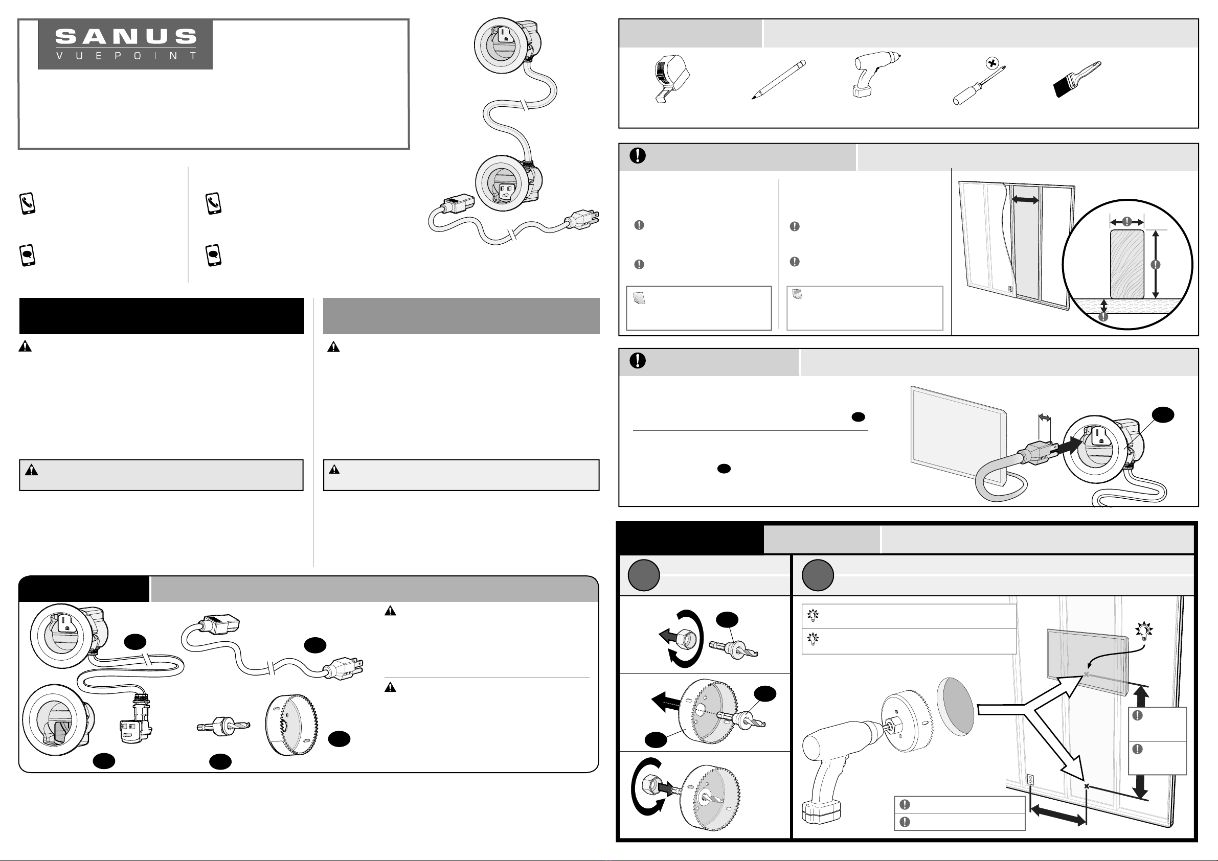
BEFORE DRILLING ANY HOLES:
Make sure your TV plug fits in the upper module 01 .
NOTE: Walls with blown-in type
insulation may require removal of
some insulation inside the cavity.
Verify Wall Compatibility Verificar la Compatibilidad de la Pared
Verify TV Plug Fit Verificar el Ajuste del Enchufe de TV
Milestone AV Technologies and its aliated corporations and subsidiaries (collectively, “Milestone”), intend to make this manual accurate and complete. However, Milestone makes no claim
that the information contained herein covers all details, conditions, or variations. Nor does it provide for every possible contingency in connection with the installation or use of this product.
The information contained in this document is subject to change without notice or obligation of any kind. Milestone makes no representation of warranty, expressed or implied, regarding the
information contained herein. Milestone assumes no responsibility for accuracy, completeness or suciency of the information contained in this document.
©2018 Milestone AV Technologies. All rights reserved. SANUS VuePoint and the VuePoint logo are trademarks of Milestone.
Milestone Global Headquarters 6436 City West Parkway; Eden Prairie, MN 55344 USA
Call us at: Llámenos al:
1-888-333-9952 1-888-333-9952
Or, chat at: O contacte con nosotros por chat en:
SANUS.com/chatSV SANUS.com/chatSV
WE’RE HERE TO HELP
vuepoint.SANUS.com
STEP 1
v
Upper Module
Driver Bit (hole saw)
Hole Saw
3 in.
(76 mm)
Lower Module
Power Cord 03
04
05
02
01
Assemble Hole Saw
abDrill Holes
DRILL HOLES
TIP: Drill the top hole BEHIND your TV.
CONSEJO: Perfore el orificio superior DETRÁS
de su televisor.
05
04
04
ANTES DE PERFORAR ORIFICIOS EN LA PARED:
Verifique que el enchufe del televisor se conecte
a la unidad superior 01 .
El Kit de Cables está diseñado para
ser colocado en paredes internas y
externas construidas con:
NOTA: Las parades externas con
aislamiento soplado pueden requerir la
extracción de parte del aislamiento de la
cavidad de la pared.
Ensamble la Sierra Perforadora
Herramientas Necesarias
Lápiz DestornilladorCinta métrica Taladro eléctrico
PRECAUCIÓN: Evite posibles lesiones personales y daños materiales.
●Lea atentamente estas instrucciones en su totalidad para asegurarse de
que está familiarizado con el sencillo proceso de instalación.
●No utilice este producto para ningún otro propósito que no sea el
explícitamente especificado por el fabricante
●El fabricante no se responsabiliza de ningún daño o lesión resultante
del montaje incorrecto o el uso indebido
●Si no entiende las instrucciones o si tiene dudas acerca de la
seguridad de la instalación, el montaje o el uso del producto, póngase
en contacto con el Servicio de Atención al Cliente o llame a nuestro
servicio técnico al número 1-888-333-9952 .
ADVERTENCIA: Este producto contiene piezas pequeñas
que, en caso de ser tragadas, podrían causar asfixia.
Antes de comenzar a montar la unidad, verifique que dispone de
todas las piezas y que se encuentran en buen estado. Si no dispone
de todas las piezas o alguna está dañada, no devuelva el elemento
defectuoso al distribuidor. Póngase en contacto con el Servicio de
Atención al Cliente.
Nunca utilice piezas en mal estado.
01
Los sistemas eléctricos cumplen con los requisitos del C6digo Electrico Nacional
(National Electlical Code, NEC) actual o con los c6digos lmpuestos por las
autorldades locales y deben conectarse a tierra consecuentemente.
Todos los productos electrlcos pueden presentar un riesgo de descarga o incendlo
si se los instala o utillza lncorrectamente. Los productos electricos Legrand pueden
llevar la marca de un laboratorio de pruebas reconocldo a nlvel nacional y se deben
lnstalar conforms al c6digo local en vlgencla o al C6digo Electrlco Nacional.
Perfore Agujeros
PERFORE AGUJEROS
Maximum Distance: 6 feet
Distancia máxima: 182 cm.
Maximum
Height:
5 feet
Altura
Máxima:
152 cm.
ESTAMOS AQUÍ PARA AYUDARLE
Tamaño mínimo del montante de madera:
Nominal 5,1 x 7,6 cm.
(Actual 3,8 x 6,4 cm.)
Grosor mínimo de paneles de yeso:
1,3 cm.
1020439 05/18
Modulo Superior
Modulo Inferior
Sierra Perforadora
Cable de Energía
Bit de Conductor (Sierra Perforadora)


