SANY SY155U User manual

SY155U
QUICK
START
GUIDE

SY155U QUICK START GUIDE
01
SY155U Display
10
12
05 06
11
08
09
07
01 Error Message
02 Machine Emergency Stop Active
03 GPS Active
04 Date And Time
05 Tool Selection Display
06 DEF Level Gauge
07 Engine Speed (RPM)
08 Engine Coolant Temperature
09 Camera Display
10 Work Mode
11 Throttle Position
12 Fuel Gauge
13 Work Mode Selection
14 Auto Engine Idle
15 Travel Speed Selection
16 Camera Settings
17 Main Menu
01 02 03 04
13 14 15 16 17

02
Display Icon Value Colour Function
Grey Normal Status
Green Escape Mode
Red Engine Power Limited
Grey Normal Status
Green Automatic Regeneration
Yellow Manual Regeneration Required
Yellow Manual Regeneration in Progress
Red Engine Torque Alarm
Red Primary Limitation of Engine Torque
Red Ultimate Limitation of Engine Torque
Grey Normal Status
Red Heat
Grey Normal Status
Yellow Hight Exhaust Temperature
Grey Normal Status
Yellow Manual Regeneration Required
Yellow Manual Regeneration in Progress
Red DPF Change Required
Grey Normal Status
Yellow Oil Change Required
Red Too Low Engine Oil Pressure
Grey Normal Status
Green Maintenance Required
Yellow Error Code
Grey Normal Status
Yellow Primary Overload Alarm
Red Ultimate Overload Alarm
Grey Battery Being Charged
Red Low Battery Voltage
Red Low Battery
1HZ
3HZ

SY155U QUICK START GUIDE
03
Work Modes
01 The machine work mode is
enabled by selecting the desired
mode on the soft keypad at the
bottom of the display. Press the
Mode Select button to cycle
through options.
01
01
Work Mode
S
H
L
B
Operation
Standard / Normal operation.
Heavy Duty Mode. For when additional power is required for heavy applications. Power Boost.
Light Duty / Lifting. For when fine control is required.
Breaker. This mode prioritises hydraulic oil flow to auxiliary lines over general machine services.
If a machine is left in this mode and then an operator tries to dig, the machine may feel
underpowered and sluggish.

04
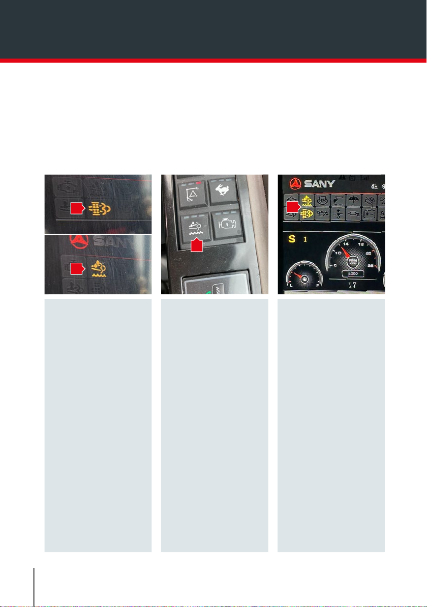
01 The machine will run an auto regen as
required to clear soot from the exhaust
system.
For the regen to commence the machine
must meet certain parameters with regards
to temperature.
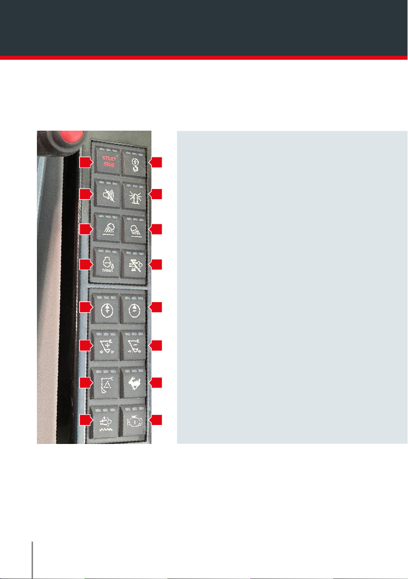
When the Auto Regen light illuminates
continue to work the machine normally until
the regen has completed.
02 A regen can be inhibited in the event that
carrying out the process with high exhaust
temperatures may cause a health and safety
concern, for example the machine is working
next to flammable material.
To inhibit the regen press the Inhibit switch
on the front right hand softkey pad.
The regen will stop and the Regen Inhibit light will illuminate on the display.
The machine can now be moved to a safe area to allow the process to continue.
* DO NOT inhibit regens unnecessarily.
* All inhibits are recorded within the machine ECU.
* Multiple inhibits will lead to a service regen being required or may result in damage to the
exhaust system. Damage caused in this way is NOT covered by warranty.
Exhaust Regeneration
01
02

SY155U QUICK START GUIDE
05
The regen will stop and the Regen Inhibit light will illuminate on the display.
The machine can now be moved to a safe area to allow the process to continue.
* DO NOT inhibit regens unnecessarily.
* All inhibits are recorded within the machine ECU.
* Multiple inhibits will lead to a service regen being required or may result in damage to the
exhaust system. Damage caused in this way is NOT covered by warranty.
3
6
Manual Regeneration
1 2
A manual regeneration is only available if the machine requests one. It will only do so if automatic
regenerations have been inhibited or cancelled.
01
01
03
02
01 The two
regeneration lights
will flash yellow
alternately letting
the operator know
a manual
regeneration is
required.
02 To carry out a
manual regen the
machine must be
up to operating
temperature.
The safety lever
must be down.
The throttle dial
must be on 1.
Select the
regeneration
button on the rear
right hand softkey
pad.
03 Once the regen has
started the yellow
regen lights will
both be illuminated
together, and the
machine will
increase the
engine RPM
automatically.
The Manual Regen light
will stay illuminated
throughout the process
DO NOT leave the
machine unattended.
DO NOT select any
services or operate the
machine.
DO NOT open the
bonnet. Exhaust
temperatures may be in
excess of 700 degrees
centigrade.

06
01 To enter the tool select menu, press and hold
the Auto Idle button on the bottom of the
display for 3 seconds.
02 Select the tool you require by navigating up
and down with the soft keys on the bottom of
the display. Once the tool you require is
highlighted green, press the Tick soft key to
store the selected tool for operation.
1. Bucket
2. Breaker/ Hammer
3. Shear/ Grab, Rotate
4. Quick Hitch
5. C1 – Programmable option
6. C2- Programmable option
Tool Selection
01
02 02

SY155U QUICK START GUIDE
07
3
6
*Figures on the display screen are a guide percentage. All flows should be verified using a flow meter to ensure
the attachment flow is correct.
3
6
3
6
Tool Setup
1 2
01
03
01 To access tool flow
setup,
Switch machine
ignition on, engine
off.
Select the required
tool.
Hydraulic isolation
lever in work
position.
Press the
highlighted button.
02 The second picture
will come up on
the display.
AUX1+:
Is RR,right
handle slider to
right.
AUX1-:
Is RL,right handle
slider to left.
AUX2+:
Is LR,left handle
slider to right.
AUX2-:
Is LL,left handle
slider to left.
03 To adjust the Flow,
Hold your AUX
slider in the
direction required.
Hold slider into
required position.
To increase flow
press + button (A).
To decrease flow
press – button (B).
02
A B

08
3
6
3
6
01 To access the quick hitch page, press and
hold the Travel Speed selection button for 5
seconds.
The quick coupler activation screen will
appear.
02 To unlock the hitch, first you must;
Activate the quick hitch by pressing the Activate
Quick Coupler soft key (1) (buzzer will sound).
Then press the Unlock soft key (2).
Select right hand button on left hand lever control
and press throughout the entire detachment
process.
Crowd the bucket fully in to detach.
Whilst still holding the button connect the next
attachment.
Quick Hitch Process
01
02 02
02

SY155U QUICK START GUIDE
09
1. Start-Stop Switch
2. Overload Alarm Switch (Optional)
3. Alarm Switch
4. Amber Beacon Switch
5. Front Work Lights Switch
6. Rear Work Light Switch (Not Equipped)
7. Auto-deceleration Switch
8. Regeneration Inhibit Switch
9. Aux Flow Increase
10. Aux Flow Decrease
11. Not Used
12. Not Used
13. Work Mode Change
14. Travel Speed Selection
15. Manual Regeneration Switch
16. Engine Escape Mode Switch
Softkey Pad
01 02
03 04
05 06
07 08
09 10
11 12
13 14
15 16

10
1. Start-Stop Switch
2. Overload Alarm Switch (Optional)
3. Alarm Switch
4. Amber Beacon Switch
5. Front Work Lights Switch
6. Rear Work Light Switch (Not Equipped)
7. Auto-deceleration Switch
8. Regeneration Inhibit Switch
9. Aux Flow Increase
10. Aux Flow Decrease
11. Not Used
12. Not Used
13. Work Mode Change
14. Travel Speed Selection
15. Manual Regeneration Switch
16. Engine Escape Mode Switch
1. Ignition Switch
2. Hydraulic Dozer Blade
3. Travel Speed Selection Button
4. Windscreen Wiper
• First Position, Intermittent Wipe
• Second Position, Constant Wipe
5. Windscreen Wash
6. Engine Speed Throttle Dial
Arm Rest
01
02
03
04
05
06

SY155U QUICK START GUIDE
11
Check
As required
Maintenance Work
Air Filter
Coolant
Radiator Cooling Fins
Air Conditioning System Coolant
Track Tension
Track Shoes Fastening
Bucket
Bucket Teeth
Roof Hatch Gas Spring
I
I
I
I
I
I
I
I
I
C
C
C
R
R
R
R
R
R
L A
A
A
A
A
Service Intervals Guide
Regular inspection
Daily Inspection
Every 250hrs
Every 500hrs*
Every 1000hrs
Every 2000hrs
Every 4000hrs
Every 6yrs
Every 10,000hrs
Maintenance Work
Water build-up in the Fuel System
Engine Oil
Lubrication Points
Engine Oil
Air Filter
Climate Control
Engine Oil Filter
Engine Oil
Swing Motor Oil
Final Drive Motor Oil
Slewing Gear
Fuel Filter
Fuel Pre-filter
Radiator Cooling Fins
Hydraulic Hose Connections
Hydraulic Oil Return Filter
Hydraulic Pilot Oil Filter
Fan Belt / Aux Belt
Final Drive Motor Oil
DEF Tank Filter
DEF Pump Filter
Swing Motor Oil
Fan Belt/Aux Belt
Coolant
Hydraulic Oil Suction Filter
Alternator
Starter
Valve Play, Engine
Water Pump
Hydraulic Oil Suction Filter
Hydraulic Oil**
Hydraulic Pipes
SANY Service
I
I
I
I
I
I
I
I
I
I
I
I
I
I
I
I
I
C
C
C
C
C
C
C
C
R
R
R
R
R
R
R
R
R
R
R
R
R
R
R
R
L
L
L
A
A
A
A
A
A
A

12
Maintenance Steps
Final Drive Motor Oil
Boom Swing Pin
Boom Swing Cylinder Pin
Boom Pins
Boom Socket-head Bolts
Boom / Arm Connecting Pin
Arm Cylinder Pin
Arm / Bucket Connecting Pin
Bucket Socket-head Pins
Slewing Gear
Slewing Ring Raceway
Blade Pin
Blade Cylinder Pin
Door Pin
Track Tensioner
L
L
L
L
L
L
L
L
L
L
L
L
L
L
L
L
I, A
L
L
L
L
L
L
L
L
L
L
L
L
I, A
R
L
L
L
L
L
L
L
L
L
L
L
L
I, A
L
L
L
I, A I, A
R
I, A
R
I, AI, A I, A
After (hr) Every (hr)
50hrs 100hrs 500hrs 50hrs8hrs 100hrs 200hrs 250hrs 500hrs 1000hrs 2000hrs 2500hrs 4000hrs
Service Refill Capacities
Fuel Tank 245 I
Engine Coolant 23.6 I
Engine Oil 15 I
Drive Motor (per side) 1.8 I
Adblue 20 I
Hydraulic Oil Tank 140 I
* First 500hrs all oils and filters changed except Hydraulic oil
** Hydraulic oil must be changed at 2000hrs if used with attachments
Machine Dimensions
Overall Length 8,015 mm
Overall Width (700mm tracks) 2,690 mm
Overall Width (600mm tracks) 2,590 mm
Overall Width of Superstructure 2,490 mm
Overall Height above Cab 2,820 mm
KEY
Inspect
I
Clean C
Replace R
Lubricate L
Adjust A

SY155U Quick Start Guide
Other manuals for SY155U
1
Table of contents
Other SANY Excavator manuals