manuals.online logo
Brands
  1. Home
  2. •
  3. Brands
  4. •
  5. Sanyo
  6. •
  7. CD Player
  8. •
  9. Sanyo CP10 User manual

Sanyo CP10 User manual

Other Sanyo CD Player manuals

Sanyo MCD-S870F User manual

Sanyo

Sanyo MCD-S870F User manual

Sanyo CDP-MT500 User manual

Sanyo

Sanyo CDP-MT500 User manual

Sanyo RM-CD23 User manual

Sanyo

Sanyo RM-CD23 User manual

Sanyo CDP-150 User manual

Sanyo

Sanyo CDP-150 User manual

Sanyo MCD-S840F User manual

Sanyo

Sanyo MCD-S840F User manual

Sanyo MCD-UB685M User manual

Sanyo

Sanyo MCD-UB685M User manual

Sanyo Excedio CDF-201 User manual

Sanyo

Sanyo Excedio CDF-201 User manual

Sanyo MCD-290F User manual

Sanyo

Sanyo MCD-290F User manual

Sanyo DV-S100 User manual

Sanyo

Sanyo DV-S100 User manual

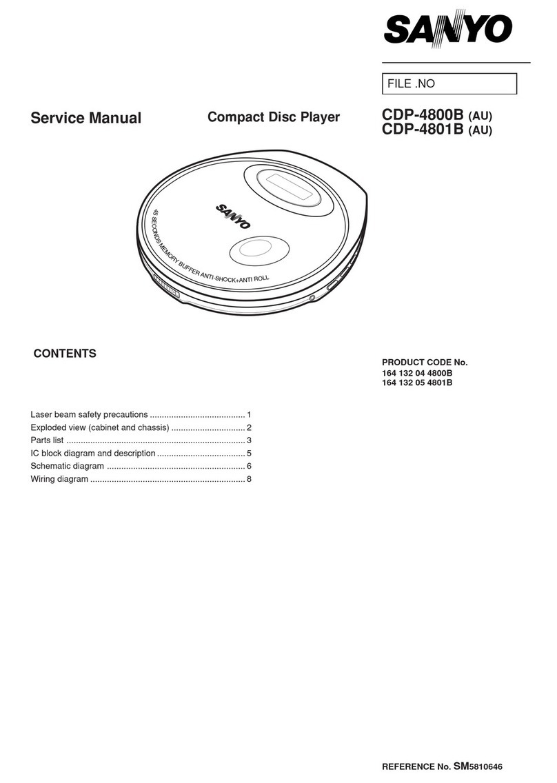
Sanyo CDP-4800B User manual

Sanyo

Sanyo CDP-4800B User manual
Sanyo FXD-CI00 User manual

Sanyo

Sanyo FXD-CI00 User manual

Sanyo CDP-244 User manual

Sanyo

Sanyo CDP-244 User manual

Sanyo CDP-905CR User manual

Sanyo

Sanyo CDP-905CR User manual

Sanyo DC DJI User manual

Sanyo

Sanyo DC DJI User manual

Sanyo MCD-S735F User manual

Sanyo

Sanyo MCD-S735F User manual

Sanyo CDP-360 User manual

Sanyo

Sanyo CDP-360 User manual

Sanyo CDP-970 User manual

Sanyo

Sanyo CDP-970 User manual

Sanyo CDP-4700 User manual

Sanyo

Sanyo CDP-4700 User manual

Sanyo FXD-603GD User manual

Sanyo

Sanyo FXD-603GD User manual

Sanyo MCD-S670F User manual

Sanyo

Sanyo MCD-S670F User manual

Sanyo MCD-XP630 User manual

Sanyo

Sanyo MCD-XP630 User manual

Sanyo FXD-C300 User manual

Sanyo

Sanyo FXD-C300 User manual

Sanyo MCD-S735F User manual

Sanyo

Sanyo MCD-S735F User manual

Sanyo VCD-X220 User manual

Sanyo

Sanyo VCD-X220 User manual

Popular CD Player manuals by other brands

Arcam CD23 Handbook

Arcam

Arcam CD23 Handbook

JVC RC-ST3SL instructions

JVC

JVC RC-ST3SL instructions

Technics SL-P9066 operating instructions

Technics

Technics SL-P9066 operating instructions

Marantz HD-CD1 quick start guide

Marantz

Marantz HD-CD1 quick start guide

Sony DVP-FX850 Service manual

Sony

Sony DVP-FX850 Service manual

Philips AZ1140 Instrukcja obs?ugi

Philips

Philips AZ1140 Instrukcja obs?ugi

Alpine 7909 owner's manual

Alpine

Alpine 7909 owner's manual

JVC CH-X350 instructions

JVC

JVC CH-X350 instructions

RCA RP-7923 instruction manual

RCA

RCA RP-7923 instruction manual

Pioneer DEH-P3550MP XM Operation manual

Pioneer

Pioneer DEH-P3550MP XM Operation manual

Philips Shockproof AX2102 brochure

Philips

Philips Shockproof AX2102 brochure

Philips CD582 user manual

Philips

Philips CD582 user manual

Philips AZ 6821 operating manual

Philips

Philips AZ 6821 operating manual

Lasonic MSU-2020 user manual

Lasonic

Lasonic MSU-2020 user manual

Denon DCD-1420 Service manual

Denon

Denon DCD-1420 Service manual

Panasonic SJ-MR100 operating instructions

Panasonic

Panasonic SJ-MR100 operating instructions

Onkyo DX-7210 instruction manual

Onkyo

Onkyo DX-7210 instruction manual

Cambridge Audio SONATA CD30 manual 

Cambridge Audio

Cambridge Audio SONATA CD30 manual 

manuals.online logo
manuals.online logoBrands
  • About & Mission
  • Contact us
  • Privacy Policy
  • Terms and Conditions

Copyright 2025 Manuals.Online. All Rights Reserved.

SERVICE
MANUAL
COMPACT
DISC
PLAYER
[|
|
=
(GENERAL)
(U.S.A)
(CANADA)
(AUSTRALIA)
(EUROPE)
(ITALY)
CONTENTS
SPECHAICATIONS
34.
Geerity
pies
Sia
aald
ace
aa
RS
one
BAG
tod
ai
AS
ae
Be
ane
it
Ciera
Re,
ees,
Sa
1
BEFORE
DISASSEMBLING
AND
REPAIRING
2.00...
eee
1
PRECAUTION
FOR
HANDLING
PICKUP
©...
ee
ee
ee
eee
es
2
DESCRIPTION
OF
LASER
BEAMCONTROL
CIRCUIT
J...
ee
ee
ee
3
DETAILS:
OF
PICKUP
oi55
facie
eee
pa
tea
wee
ae
ee
ae
he
ie
Se
eee
Faas
eae
ee
Ses
4
DISASSEMBLY:
5
oan
cw
Ste
GAA
eae
dee
PREMERA
SAS
ES
Ea
SG
go
ghee
GE
Dew
acest
5
ADJUSTMENT
odo
vetis-
eS
a8
a
oe
o-
aieheet
ens
Gow
Tikes
Ges
Pe
ne
bald
ceed
ad
Gaeta
sew
Biel
Benes
8
NORMAL
WAVE
FOAMOF
TEST
POINT
..
0.0...
00...
c
ee
eee
ee
eee
ee
eee
eet
eee
1
IC
BLOCK
DIAGRAM
............00
0000 wees
wae
ee
ME
os
eM
sna,
By
BUR gay
Way
ond
ENS,
ae
ae
eee
14
EXPLODED
VIEW
(
CABINET
)
i
ge
See
Ga ee
ee
a
Se
Pe
ee
ee
eS
ee
ae
eee
24
PARTS
IST
wut
coca
tnete
dees
is
Sek
Sees
REY
lh
ee
aed
okay
alos
nant
as
sik
Pe
ple
oP
ohn
tts
ae
Bedard
25
EXPLODED
VIEW
{
MECHANISM)
00.0.0...
0c
cece
scene
eens
eens
nese
tee
en
eee
eaen
enemies
30
PARTS
EIST
MECHANISM).
556,
20.0
be
ese
REGED
See
ee
ees
eed
Lem
eae
a
eee
oe
31
BEOCK
DIAGRAM:
0.0035.
oS
ashas
qatar
eld
bate
Da
AS
ela
Sodas
BE Vi
we
oT
bw
ae
al
atalen
a
ale
Sees
32
WIRING
CONNECTION
DIAGRAM
..
0...
6
ee
ee
eee
eee
ee
EE
34
SCHEMATIC
DIAGRAM
Occcc
bai
are
SS
Ee
ONG
Sele
ae
ee
a
ee
ey
ee
es
VE
a
Ra
36
WIRING.
DIAGRAM:(
MAING
6
ou
ok
oe
ee
ce
oe
eae
he
Pe
MR
Oe
EE
Be
SS
Ea
Ra
Bo
38
SCHEMATIC
AND
WIRING
DIAGRAM
(
AC
SOCKET,
DC
POWER
P.C.BOARD)
............0..000065
40
TROUBLESHOOTING
FLOW
CHART
4s
ctgig
weoe
dh
oe
ae
lee
Re
a
els
in
Ow
eS
A
es
a
Ba
42
WIRING
DIAGRAM
COTHERS.):
3a
eee
de
ore
eS
pe
one
eee
a
ERE
Ca
ka
ge
ewes
44
IC:
BEOCK
DIAGRAM
Wo
sa
hen
eGo
ea
oo
ees
CHER
Sa
Eos
UG
hg
se
Daa
ee
nei
eee
Re
45
WM-17964
en’
SPECIFICATIONS
Audio
General
Channels............
2channels
Power
supply.........
AC
110-127/200-220/230-250V
e
Frequency
response
....20
—
20,000
Hz
50/60Hz
...
GENERAL
Dynamic
range........
90
dB
AG
120V
60Hz
...
U.S.A,
Channel
separation
.....
80 dB
(
1
KHz)
CANADA
ohana
bene
e
sees
aoe.
:
a
)
AC
240V
50Hz
...
AUSTRALIA
ow
and
flutter
.......
ndetectable
AC
220V
50Hz
...
EUROPE
Outputs
..........6.
LINE
OUT:
1.6V/50K
ohms
‘
ITALY
E:
HEADPHONE:
30mW/32
ohms
DC
+7.2V~
B4V
Signal
format
Power
consumption
....10W
Sampling
frequency
....44.1
KHz
Dimentions
..........
approx.
127
x
41.5
x
187
mm
Quantization
.........
16
bits
linear/channel
(WxHxD)
(5x
1-5/8”
x
7-3/8")
Weight
{
approx.)......
900
g(
1
Ibs.
15
oz.
)
Pickup
System
............0.
Objective
drive
system
light
pickup
ee
,
Light
source
.........
Semiconductor
laser
Specifications
and
design
subject
to
change
without
notice.
=
Wave
length..........
790
nm
BEFORE
DISASSEMBLING
AND
REPAIRING
a
Many
ICs
and
a
pickup
are
used
in
this
compact
disc
player
and
these
components
are
very
sensitive
to
static
electricity
and
can
break
down
if
exposed
toa
high
static
voltage.
They
must
therefore
be
handled
very
carefully,
b
Since
pickup
consists
of
many
optical
components
and
other
precision
components,
do
not
repair
it
or
store
it
in
a
hot
or
humid
place,
near
strong
mangetic
fields,
or
in
a
dusty
location.
c¢
When
replacing
any
of
the
components
of
a
CD
player,
first
switch
OFF
the
player
and
disconnect
the
power
cord
from
the
player.
d
Ground
all
equipments,
measuring
instruments,
and
tools.
e
Place
an
electrically
conductive
sheet
on
the
work
bench
and
ground
it.
After
removing
a
pickup
from
its
conductive
pouch,
do
not
place
it
on
the
pouch.
Because
it
may
be
damaged
due
to
static
electricity.
f
Ground
a
soldering
iron
to
prevent
AC
leakage.
g
Ground
a
worker
with
metal
band
(
1M
ohms
)
to
ground
static
electricity
which
may
build
up
on
the
body,
h
Because
static
electricity
which
builds
up
on
clothing
does
not
ground
through
the
metal
band,
be
careful
not
to
touch
your
clothing
to
the
pickup.
i
Do
not
directly
look
at
the
laser
beam
emitted
from
the
pickup
or
aim
it
at
your
fingers
or
skin.
Armband
Resistor
(1M
ohm)
Senate
Sheet
Resistor
—*
(1M
ohm)
what,
PRECAUTION
FOR
HANDLING
PICKUP
—-_-_———————————
#
(1)
a
4
b
(2)
c
\
d
.
e
)
f
Precautions
for
transportion
and
storage
Store
the
pickup
in
its
conductive
pouch
until
just
before
using
it.
:
Do
not
apply
external
pressure
or
shock
to
the
Pick-
up,
ressure
x
Pressure
Dropping
store
in
conductive
pouch
Magnet
Precautions
for
handling
of
the
pickup
Since
the
pickup
has
a
powerful
magnet
in
itself,
do
not
leave
it
near
a
magnetic
field.
When
handling
the
Pickup,
hold
it
correctly,
and
do
not
apply
external
pressure
or
shock
to
it.
If
you
apply
extremely
strong
pressure
or
shock
to
it,
it
may
mulfunction
or
its
printed
circuit
board
may
crack,
The
pickup
is
a
single
component
and
has
been
accu-
rately
adjusted
as
such.
Do
not
touch
any
adjustment
point
and
mounting
screws.
If
the
laser
beam
strikes
your
eye,
it
may
be
damaged.
Do
not
under
any
circumstances
allow
the
laser
beam
to
strike
the
eye.
Also,
do
not
under
any
circum-
stances
apply
a
voltage
to
a
pickup
whose
laser
out-
put
section
(
objective
lens,
etc.
)
is
damaged.
Method
of
holding
pickup
Laser
Beam
Cleaning
lens
surface
If
dust
gets
onto
the
surface
of
the
lens,
blow
it
away
using
an
air
brush.
The
lens
is
retained
by
an
extreme-
ly
delicate
support
spring.
When
cleaning
the
lens
surface,
therefore,
use
a
soft
cotton
stick
moistened
with
iso-propy!
alcohol
and
clean
the
lens
very
gently,
taking
care
not
to
bend
the
support
spring.
(
other
liquid
may
injure
the
lens
)
Also,
do
not
use
an
ex-
cessive
amount
of
cleaning
fluid
otherwise
it
will
flow
into
the
pickup.
Do
not
disassemble
the
pickup.
Do
not
directly
look
at
the
laser
beam
or
aim
it
at
the
fingers
or
skin.
COTTON
SWAB
CONDUCTIVE
SHEET
DESCRIPTION
OF
LESER
BEAM
CONTROL
CIRCUIT
(1)
Laser
operation
circuit
(2)
Operation
of
the
circuit
a_
By
turning
“ON”
the
POWER
switch
(S601)
after
the
power
cord
is
plugged
in
or
the
battery
pack
is
con-
nected
to
the
unit,
then
closing
the
top
lid,
the
CLOSE
switch
(S609)
[
and
LASER
switch
($901)
hoa
a
eet
EUROPE/AUSTRALIA/ITALY
only
}
will
go
EUROPE
“ON”,
and
pin
35
of
1C501
(OPEN/CLOSE)
becomes
ae
aay
pecpOweR
“LOW”
level.
Fu
eae
only
b
Press
the
PLAY
key
(S604)
or
the
MEMORY
key
5901
|
|
CIRCUIT
ney
(S605).
While
the
key
is
pressed,
pin
15
(PLAY/
ana
diy
PAUSE)
or
pin
16
(MEMORY)
of
IC501
becomes
:
i
ON/OFF
“LOW”,
c
Pin
19
(HOLD)
of
1C501
becomes
“HIGH”,
and
the
hold
condition
of
1C501
will
be
cancelled.
d
Consequently,
pin
28
(P-CONTL)
of
1C501
becomes
"LOW",
and
“HIGH”
voltage
will
be
applied
to
the
POWER
ON/OFF
terminal
of
the
+5.2V
DC
POWER
BLOCK
via
0502.
e
-—5,2V
output
from
DC
POWER
BLOCK
is
applied
to
the
APC
circuit
of
the
pickup,
and
causing
the
pickup
emits
the
laser
beam.
Safety
Operation
1c801
@
a
When
the
top
lid
of
the
unit
is
open
with
the
POWER
SPEN
IETOEE
a
|e
switch
is
“ON”,
even
if
you
press
the
PLAY
key
or
MEMORY
key,
the
pickup
will
not
emit
laser
beam
because
the
CLOSE
switch
(S609)
[
and
LASER
1c501
(15),
(6)
i
f
ais
switch
(S901)
.....
EUROPE/AUSTRALIA/ITALY
PLAY
/
PA
PLAY
/
PAUSE.
only
]
is
“OFF”
and
pin
35
of
IC501
remains
“HIGH”.
MEMORY
ry
When
the
PLAY
or
MEMORY
key
is
pressed
without
i
loading
a
disc,
the
pickup
emits
laser
beam,
but
sever-
1c501
| |
al
ener
later
it
will
ep
to
emit
laser
beam
as
safety
HOLD
===>
circuit
defects
that
there
is
no
disc.
c
Even
in
the
event
that
1C501
breaks
down
and
the
10501
@8)
pickup
emits
laser
beam,
it
will
not
directly
enter
the
P-CONTL
eye
because
of
the
opaque
cover.
+5,2V
DC
POWER
ee
ae
POWER
ON/OFF
ov
-5.2V
ee
eee
52V
----
lou
DETAILS
OF
PICKUP
as)
(1)
Appearance
ACTUATOR
y
FPC
TERMINAL
LASER
DRIVE
CIRCUIT
OBJECTIVE
LENS
FPC
TERMINAL
PHOTO
SIGNAL
SENSOR
FPC
TERMINAL
(2)
Optical
system
)
COMPACT
DISC
FOCUS
+t>
TRACKING
LASER
DIODE
OIFFRACTION
GRATING
LASER
DRIVE
ACTUATOR
PHOTO
DIODE
CIRCUIT
FOCUS
OOIL
TRACKING
COIL
(3)
Wiring
diagram
GND
PHOTO
SIGNAL
DETECTO
OD®OO®O®O
GND
-Sv
FO
FO:
TO
TO
LASER
DRIVE
CIRCUIT
ACTUATOR
FO
GND
TO
-5V
be
5
FO
T
DISASSEMBLY
in
and
Sub
PCB
removals
*
|f
there
is
a
compact
disc
(CD)
in
the
player,
remove
(3)
Main
an
it.
*
Disconnect
the
power
plug
from
the
player.
*
Disassemble
the
player
in
the
following
sequence:
(1)
Bottom
lid
removal
ACTUATOR
TERMINAL
g
AR
S
‘
|
PHOTO
SIGNAL
SENSOR
FPC
TERMINAL
ah
LASER
DRIVE
sean
|
CIRCUIT
ue
‘
cB
(4)
Volume
PCB
removal
DISASSEMBLY
(5)
Other
PCB
removal
(6)
Top
lid
and
LCD
removals
8
5
T.
4
ey
PC
D
BRACKET
[-s
Ss
Qes~
RCA
SOCKET
OC
POWER
PC
Bf
y
Z
(7)
Circuit
bord
arrangement
figure
j
DC
POWER
PCB
LCD
VOLUME
PCB
MAIN
PCB
KEY
SWITCH
PCB
DISASSEMBLY
The
compact
disc
is
a
very
delicate
mechanism.
It
is
very
Important
that
the
spindle
motor
(which
rotates
the
disc),
the
sled
motor,
the
worm
gear,
etc.all
operte
smoothly
and
without
eccentricity.
Care
must
be
taken
not
to
exert
excessive
force
on
the
pickup
and
particular
care
must
be
taken
not
to
touch
either
the
jens
or
the
lens-control
circuitry.replacement
of
the
spindle
motor
(8)
Replacement
of
spindle
motor
a
Remove
the
two
screw
(Y13)
which
hold
escutcheon
mecha
cover
(see
exploded
view,
Ref
no
15,
16
of
page
30.)
b
Remove
the
two
screw
(
11
)
then,
after
removing
the
upper
pulley,
universal
pulley
and
spring.
c
Loosen
screw
(
12
)
which
hold
tarntable.
d
Remove
the
two
screw
(
13)
and
then
replace
the
spindle
motor.
e
After
fixed
the
spindle
motor,
set
the
turntable
upper
surface
so
that
ti
is
4mm
+
0.1mm
above
the
chassis.
f
With
the
smaller
diameter
end
of
the
spring
coil
upward,
install
the
universal
pulley
and
upper
pulley,
and
then
secure
by
using
the
two
screws
(
11
)
for
holding
the
supper
pulley.
g
Check
to
be
sure
that
the
universal
pulley
moves
smoothly
up
and
down.
TURN
TABLE
SPINDLE
MOTOR
(9)
Replacement
of
sled
motor
and
belt
a
Remove
the
screw
and
spring
plate
with
flat
gear.
b
Remove
the
screw
(
15)
which
hold
worm
gear.
c
Remove
the
two
screw
(
16
)
which
hold
sled
motor
bracket.
Remove
the
two
screw
(
17)
which
hold
sled
motor.
e
Replace
the
sled
motor
and
belt.
(10)
Replacement
of
pick-up
a
Remove
the
screw
and
springplate
with
flat
gear.
b
Remove
the
screw
(
14
)
and
spring
plate.
c
Replace
the
pick-up.
11
&
PULLEY
CD
rier
jen
COIL
ER)
TABLE
—”
&
AP
R
ZA
{>
FAAN2
SS
13
me
?
S
ZN
a
AZ
a
~
al
=e
J)
SPINDLE
MOTOR
@15
Lp
voces
a
oe
as
@14
Gy
sPRING
PLATE
A
ADJUSTMENTS
SSS
SSS
rs
sp
hs
SSS
Sh
D
Before
making
adjustments,
please
read
the
“before
disassembling
and
repairing”
“precaution
for
handling
pickup”
“description
of
leser
beam
control
circuit”and
»
“disassembly”
*
Service
Mode
This
mode
is
used
for
adjustment
when
servicing
and
its
functions
are
incorporated
in
the
microcomputer
(1C501).
Please
read
following
explanation
carefully
to
understand
the
function
of
this
mode,
(1)
The
program
of |C
501
operates
when
the
power
switch
is
“ON”
and
reset
signal
is
input
to
pin
18
of
IC
501,
(2)
First,
select
either
a
service
program
routine
or
a
normal
routine.
(3)
If
you
select
a
service
program
routine,
the
micro-
processor
brings
the
necessary
work
from
each
sub-
routine
in
accordance
with
the
key
inputs,
then
executes
the
work,
With
this
service
mode,
you
can
efficiently
check
or
Test
disc
necessary
for
adjustment
)
Measuring
equipment
necessary
for
adjustment
Equipment
Model
No.
(manufacturer)
Synchroscope
$S5711
(100
MHz
—
Doble
reflective
BAND-PASS
FILTER
Memory
scope
DSS
6521
(storage
scope)
kikusui
Denshi
AC
digital
voltmeter
|
Digital
tester
or
digital
multimeter
is
available
IN
OUT
DC
digital
voltmeter
|
Digital
tester
or
digital
multimeter
is
available
Audio
signal
generator
Band
pass
filter
Band
pass
filter
(see
attached
drawing)
GNO
GND
Notes;
a
Other
manufactures’
equipment
which
has
same
specificat-
ions
with
ones
designated
above
may
be
used.
b
Use
a
probe
when
observing
signal
using
an
oscilloscope,
memory
scope
or
digital
voltmeter.
ADJUSTMENTS
1.
Setting
the
service
mode
(1)
(2)
(3)
(4)
Disconnect
the
AC
power
plug
from
the
unit.
Press
the
PLAY/PAUSE
key
or
the
MEMORY
key
due
to
discharge
C904
connected
to
pin
18
of
1C
501
(RESET)
and
the
+V_
IN
smoothing
capacitor
(C951).
Consequently,
pin
18
of
IC
501
becomes
“LOW”.
Ground
the
pattern
of
TP36
(see
wiring
diagram
of
page
38
~
39)
using
jumper
wire.
Two
kind
of
IC
is
used
as
!C501
in
this
unit.
Follow
step
according
to
the
particular
part
No,
concerned.
TMP47C420AF8172Z
...Connect
the
AC
power
plug.
(This
mean
is
not
operation
of
the
power
switch
ON/OFF)
TMP47C420AF8173Z
°°
.Connect
the
AC
power
plug
while
pressing
the
PLAY
key.
The
player
will
be
in
the
service
mode
and
the
LCD
displays
«
Og
og
00”
2.
Particular
operation
in
service
mode
(1)
(2)
(3)
(4)
When
the
SKIP/SEARCH
key
is
pressed,
the
pickup
moves
to
the
outermost
or
innermost
portion
of
the
disc.
This
enables
to
check
the
operation
of
the
sled
motor.
When
the
MEMORY
key
is
pressed,
the
pickup
perform
a
focus
search.
If
a
disc
is
loaded
in
the
unit,
the
focus
servo
will
go
“ON”.
If
a
disc
is
not
loaded,
the
focus
search
will
take
place
indefinitely.
When
the
REPEAT
key
is
pressed
in
the
condition
of
step
2,
the
tracking
servo
will
go
“ON”,
and
the
unit
will
go
into
a
play
condition.
When
the
STOP
key
is
pressed
at
any
operating
mode,
you
can
cancel
the
ongoing
operation.
3.
Cancelling
service
mode
Disconnect
the
AC
power
plug.
and
then
remove
the
jumper
wire
from
the
pattern
of
TP36.
(See
the
wiring
diagram
of
page
38
~
39.)
Tracking
balance
adjustment
Test
disc
;
YEDS
18
(Sony)
Measuring
equipment
;
Oscilloscope
Connection
point
;
TP-3
Adjustment
point
‘
Adjustment
value
;
a
b
SVR
-
101
Waveform
symmetry
Put
the
unit
in
the
service
mode.
Load
the
test
disc
and
then
press
the
MEMORY
key.
The
disc
will
rotate
and
the
focus
servo
will
go
ON,
Note:
!f
the
pickup
is
at
the
innermost
track,
first
press
the
PP
key
to
move
the
pickup
slightly
to
the
outside
and
not
to
play
the
TOC
(zero
pattern)
on
the
disc.
Observe
the
tracking
error
signal
(
from
TP3
)
on
the
oscilloscope
and
adjust
SVR101
so
that
the
waveform
becomes
symmetrical
with
respect
to
0
V.
(See
Fig.
1.)
Focus
offset
adjustment
Test
disc
;
YEDS
18
(Sony)
Measuring
equipment
;
Oscilloscope
Connection
point
;
TP-2
(FE-Signal)
TP
-
1
(RF-Signal)
Adjustment
point
;
SVR102
SVR
102
Adjustment
value
:
o
when
unit
in
STOP
status
Connect
the
oscilloscope
to
TP2
(FE
signal).
Connect
the
oscilloscope
to
TP1
(RF
signal).
Follow
steps
(a)
and
(b)
of
the
“Tracking
balance
adjustment”
to
turn
the
focus
servo
“ON”,
Press
the
REPEAT
key,
The
tracking
servo
will
go
ON,
and
the
player
will
be
in
a
play
condition.
Measure
the
DC
offset
voltage
of
the
waveform
[focus
error
signal
from
TP2]
using
a
DC
voltmeter,
and
note
the
measured
value.
Press
the
STOP
key
and
remove
the
disc.
Adjust
SVR102
so
that
the
DC
offset
voltage
at
TP2
becomes
the
same
as
the
voltage
measured
in
step
(e).
Re-load
the
disc,
and
then
follow
the
steps
(c)
and
(d)
to
put
the
unit
in
a
play
condition.
(MEMORY
key
“ON”
>
REPEAT
key
“ON”.)
Confirm
that
the
‘a’
portion
of
the
waveform
(RF
signal)
from
TP1
must
be
a
straight
line,
and
the
‘b’
portion
(eye
pattern)
must
be
open.
(See
Fig.
2).
Also,
verify
that
the
height
of
the
wave
is
maximum,
OPENING
EXPANDED
Ao—
Fig.
2
a
(
Voltage
when
unit
in
PLAY
=
Voltage