Sanyo DC DJI User manual

I
Service Manual
*
1.$
.. \
,,.,
~
t
,,
,I
.!
.
J
,,i
/
‘I ~\,,
,,
,,1
‘“\
‘;
,,
Specifications
Tuner Section
iii
Compact Disc Audio DC DJI (GENERAL)
Component System with
Wireless Remote Control 7
~“
PRODUCT CODENo,
13234060
DECK Secllon
FM Motor ...................,,,............0...,........... DC motor (DECK 1and DECK 2)
-FW+fGflGlQ8 received,,,,..,.,g,,.,,,,,,,,,,,,,,,,,,,,t,,,,,,,,t, 07,50 ~108.00 MHZ Head ,,,.,!,!!!,,,,.,.O.1,,,,,.. !..,..., .....0..,,,.,,..,.,,0!,,., Hi-B hard permalloy head
IHPprttllcalswtslllvlty(mono),,,,.,.............................. 343IJV/16.Sfl dBf [DECK 1riayback head, DECK 2recording head)
S/N ratio ...................................................... 65 dB (mono, 60 dBf input)
Harmonic distortion ....,.,,....0.!.. .................,,.......!.. 0.1 %(mono, 1kHz)
Stereo separation ,,,.....0.....,,,,. 0,..................,,,..,..0,,,,!.!..... 35 dB (1 kHz)
Image frequency interference ratio ............................................. 38 dB
AM
Frequencies received ................................................... 531 N1602 kHz
Pratical sensitivity (included antenna) .................................. 809 lJV/m
SIN ratio ,,..,.!.!,,...........,,,,.,,!,,..,.,., ,,,..,,.,,,,.,!,....,.,.,,.,,,,!,,,.... ,,,....... 50 dB
Image frequency interference ratio .,.,,,,,......,,,,,. !..................,.,.!. 40 dB
Soloctlvlty ....!.......................o!.........................#.....$.....................$.. 38 dB
IF interference rallo ...................................................................... 65 dB
Amplifier SectIon
output power (Front) ,,, ,,s .,, . !!,,,,.,, ..,0 .,.. ,., . . . . . . . . , ..,!..... 50 W(T.H.D 10%)
Music Dower (Front) ................................................. 80 W(T.H.D 10 %)
Inpuf sensitivity/impedance
PHONO ....................................................................... 3.0 mV/50 kCl
DATNCR ........................,..,,.....!...,.., .,,.,s,,,...,.,,... .......
AUX 180 mV/50k(l
............................................,,,,!.,,. ,,.,,...$,............. 180mV/50kfl
,,. .
.“,\Speclllcaliona and deelgn are subject to change without notice.
,,.
.’. .
,, ,. -1
.,,
,., .” \i,
,,, ,, !
,..,’...
. .Ferrite head (DECK 2erasing head)
Fast-forward/rewind time ........................ Approx. 110 sec. (C-60 tape)
Tracks .,,,.,,!.,...,,,0.,,,,.,,,..,.,,,, !..,.,,,,,,,.,...,,,..,.. 4-lrack, 2-channel slereo
S/N ralio (playback) ....................!.......,,.,...,., ................................ 50 dB
Frequency response ................................. 413HZ -16 kHz (metal taPe)
Wow and flutter ............................................................. 0.08 %(WRMS)
CD Playar Section
Frequency response ..................................................... 20 Hz -20 kHz
Harmonic dlslorlion ...................................... Less than 0.04 %(1 kHz)
S/N ralio ..............,,,,.,.,.,.,,, ........................................................!...95 dB
Wow and flutter ............................................. Below measurable limits
optical pickup .................................................................. 3-beam laser
Error correction .......0..,..,,,, ............................................................ CIRC
Sampling frequency ....................,......................................,.0,.. 44.1 kHz
D/A conversion ...............................................0.....,.,!,.!,..... 16-bit linear
Filter .................................................................................... Digitalfilter
General
power requirements .......................... AC: ~~Ol12?1220124;v, 50/60 HZ
Power consumption ....................,..,.,...!....,,,. ,.,...,, ,..,!,................. 260 W
12imenslona (WXHXD) ,,,,,,,,,,,,,,, t,,,.,,,,,,,.,,,,,,,,,,,,.,,,,,,,,, 360x455x320 mm
Weight (apptox.) .“
. .......................................#..,.’i.,,,#.,....,.............
REFERENCE No. WM-570193
12.9 kQ
,,
,,, .,

CONTENTS
Safety Certification ,J..~~f~ ~:gg.~*q g**.~!!l L!! !~!,!,,,,, ,,f,ttc!lp ,,!, tt o,,, ,,, ,, . . . .
CD PiaY6r Disassembly Procedures .................$, .,... . . . . . . . . . . . . . . . . ,., ,.,.’, ::.:
Removing the Disc Tray ,,, ,,.,, ,,, ,0,,, .,, .,,., ,., ..,.. ,. .,.0.. 0.......,0...,.0. ...
Removin~the Mechan~sm ,. .,0.,. ,, .,,.0. ., ..,.., .$
N6te for Assembling Disc Tray ..... ...... ..... .......
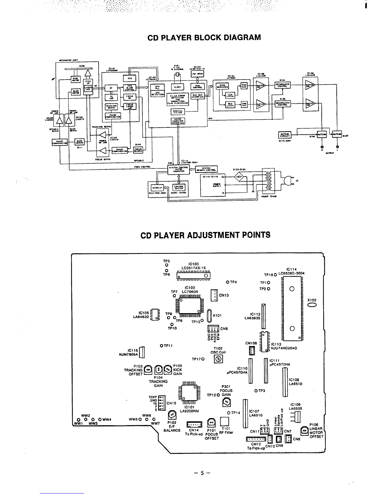
CD Player Block Diagram ,, ..0..,. ....................
CD Player Adjustment Points ...........................
CD Player Adjustment Procedures ......................
Before Checking or Adjusting CD Player ...............
. . . . . . . . . . 6....................
. . . ...0.. .....................0
...... ..... ....... ............ ..
....................0 ...,,.. . . . .
...............................
......0. .......................
Checking Focu{ErrorSignal .................................................
Free Run Frequency Adjustment . . .......
... !.... . ..0..0. ...................................
Setting of Initial Position of Volume ,., ,., ,. ,0 .,..,. ., ..,... ,,, ,, ... .,0, . . . . ,. ...,., . . .
Focus Offset Adjustment . . ., ..0... . . . . . . . . .. 0,.,.. .0 .0.... . . . . . . . . ., . . ...0 .. ......0.
Tracking Offset Adjustment ... ..,.. ,, .,,.,. . . . . . . . . . . . . . . . . . . . . . . . . ,. 0,.0.. .........
Linear Motor Offset Adjustment ,., ..,.. . . . . . . . . . . . . . . . . . . . . . . . . . . ...0.. .......... 000.
E/F Balance Adjustment ....................................,0 ...,,,. ,., ,. ,0., ......
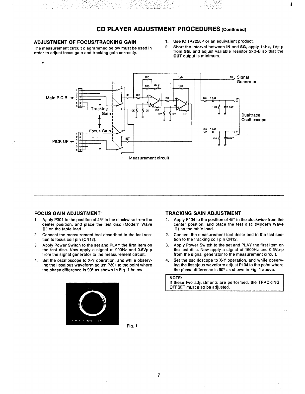
Adjustment of Focus/Tracking Gain ., .,.... . . . . . . . . . . . . . . . . .,0 .....0..,.... . . . . . . . . . . .
Focus Gain Adjustment ... .,,.,, ., .0,.,,, ., .,,,.,, ., . . ...0. 0.,..,... . . . . . . . . . . . . . . . .
Tracking Gain Adjustment . ...,,,.,. , ...4,..., ,...,,,,0, 0.?, .,,,4, ,, .,,,.,,. . . . . . . . .
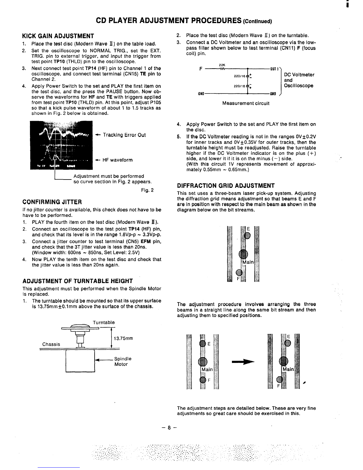
Kick Gain Adjustment ,, .,...0,. .00.,0..,. ,, .,,,,,,. , ..,.,,,.. ,,, ,,4, ,,, ,, ...4..... .
Confirming Jitter . . . . . . . . . . . . . . . . . . . . . . . . . . . ,. .,,.,,, . . . . . . . . . .. 0.,..,, .,, . .. s., 0..
Adjustment of Turntabie Height ., ,0,..., .. 0...0., . . . . . . . . . .,, ,, .,,. $. .......,. .,,,.0.
Diffraction Grid Adjustment ,. ..,... ,., ,. .,. . . . . . . . . . . . . . . . . . . . . . . . . . ..!.... .........
Diffraction Grid Adjustment .....................................................0.. .
3
4
4
4
4
5
5
6
6
6
6
6
6
6
6
6
7
7
7’
8
8
8
8
9
ii
..
,, l!.,~
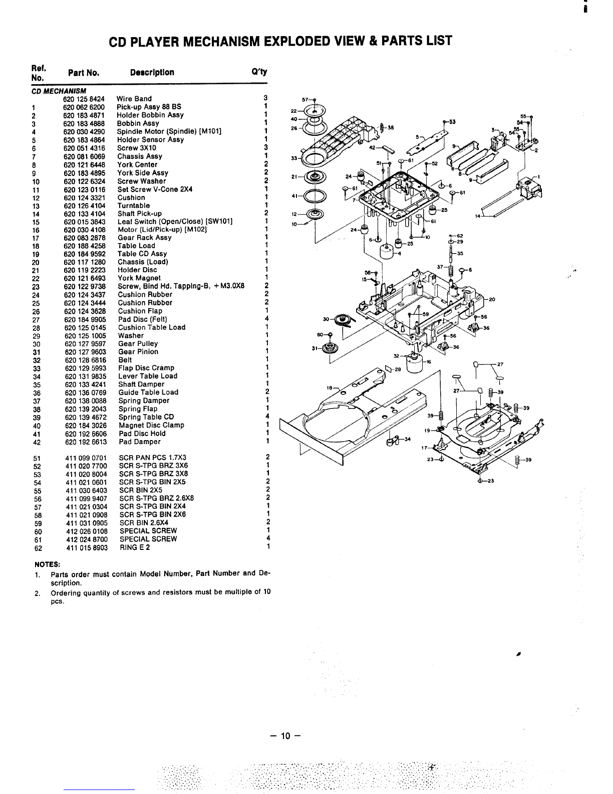
CD Player Mechanism Exploded View& Parts List ....0..,. . . . . . . . . . . . . . . . . . . .,, ,, .,.. ,.. .#. 10
Block Diagram (Main Unit Section) ................... ...0. ,, .0.... ...................... 11
System Block Diagram (Function Section) ... . . . . . ,, ..,,.. . . . . . . . . .. 0.0... 0,.,,00. .! 0.0... 12
M-COM (LC6554H)System Biock Diagram ., ..,..0. .0 .,.0.., . . .. s.,., ....................0 13
Caution on RFAdjustment . . . . . . . . . . . . . . . . . . . . ,, ..,,,.., . . . ...0... .....................14
System Ciock Adjustment ., .,,,,,, . . . . . . . . . ,,, .,,.., ,. .,..,,0 .........., .,,,,,0 Os0,... 14
FM Tuner Ailgnment ....................................... ,0.,.. ,, ..,..00 ...........14
AM Tuner Alignment . . . . . . . . . . . . . . . . . . . ..,, ,. .,,,,, .,, ..,,.,, s,, ,,, ...................15
Cassette Deck Eiectricai Adjustment . . . . . . . . . O* .,...,. ,. .,,..,, ., .,,,.,, ., .,.,,., 0,, ..,.. 16
Before Adjustment ................................................................16
Measuring instruments Required ,, ...,.. .............................................16
Switch Positions . . . . . . . . . . . . . . . . ,,, .,.., . . . . . . . . . . . . . . . . ,, .,..,. . . . . . . . . . . . . . . . . ,. 16
Normai Tape Speed Adjustment ,., ,,, ,. . . . . . . . . . . . . . . . . ,. ..,.,0 .,, .,0.. . . . . . . . . .0 .,.. 16
High Speed Tape Speed Adjustment ,., ,, .,.. ,, .0,..,. .,, ,,, ... ... ,,, ,., . . . . . . . . . . . . . .
Head Azimuth Adjustment . . . . . . . . . . . ... ..,..0 . . . . . . . . . ,., .,,.,. ., .,0..,, ..........0 ;:
Piayback Sensitivity Adjustment ............................,., ,. .0.. .................17
FL Meter Sensitivity Adjustment ,,, ..,,,, ,, ..,,.,, . . . . . . . . . ,,, ,, . . . . ... .*,,.. .........17 ..,, ‘:,
Recording Bias Level Adjustment (Deck2) .,,
......................,..0. ................0. .17 ‘“-””-’’””’i’
Cabinet Exploded View &Parts List 18 “,.
,0,,...00 .0, .,...0 .,0 ...,.... . . . . . . . . . 0. . . .. $0. .0 . . ...0
Cassette Deck Mechanism Expioded View &Parts List ‘I
. . ...0... .,, ,., ..,. . . ...0... ............21
P.C.Board Parts List ,,.
.,
. . . . . . . . ... ,., ,. 0...,... . . . . . . . . . ...0... . . ...0.. . ........ ....... ..23
P.C.Board Parts List ,,
,. .,,.,. . . . . . . . . ,, .,,,., ,. .0.... ... ...0, ,. ..0..0 ......0. . ....... ..28
Wiring Diagram (CD Piayer Section) . .,,.,,,,, .......... ,0 .,,..... . .,,0,,,,, ,,, .00...,0 . . 51
Wiring Diagram (Power Main Section) . . . . . . . . . . . . . . . . . . . . . . . . ,. .,..,, . . . . . . . . ,,, ..,., ,,, 52
Wiring Diagram (Main Unit Section) ....................................0... .............53
Schematic Diagram (Tuner Section) ......................................................55
Schematic Diagram (Deck/Function/Front Controi Section) ...................................57
Schematic Diagram (Deck/Function Section) ...................0 ..,,.,. . . . . ...0. ...... ....59
Schematic Diagram (CD Piayer Section) . . . ... . . . 0...0...’. .. ’0....., ....... ....... ........ .61
Schematic Diagram (Main Power Section) .:
..................0,, .,,.,, . . . . . . . . . ,,, ,. .,... . . 63 0
iC Block Diagram ,., ,, .,. ,,, ,,, ,! ,,, ,,, !* ,,,~~,f, ,,tt f,,,, :,~~t,,~ ,,, ,,, ,, ,,, ,. .,. ,,, , 64
IC &Transistor Lead Identltlcat{ori ,.,4,,,.,., . . . . . . . . . . 0. .,,,,..., 4. . ...*.... C** S* .4.**. .79
1,
–2–

SAFETY CERTIFICATION
0r——
UIIIIWHIO=3- IHlonnnollll
NHHUIONHI
‘- MHHlwl
m
..—
ommHHHHlllllulpcc
Ollllllollollllnllnlo“–
[/1
.
‘&[lFWavelength:755-815 nm(25”C)
LaserOutput:ContinuousWavemax.0,5mW
CAUTION -USE OF CONTROLS OR ADJUSTMENTS OR PERFORMANCE OF PROCEDURES OTHER THAN THOSE SPECIFIED
HEREIN MAY RESULT IN HAZARDOUS RADIATION EXPOSURE.
THE UNIT SHOULD NOT BE ADJUSTED OH REPAIRED BY ANYONE EXCEPT CWALIFIED SERVICE PEF190NNEL,
BEFORE USE
CD PLAYER SECTION
Using aflat-blade screwdriver, turn the transport fixing screw on the
bottom panel about 90° clockwise
●When transporting the unit again, such as when moving, remove
the disc then turn the fixing screw about 90° counterclockwise.
+“&~
b) Fixingscrew
oL.
c) Bottompanel
–3–

I
Cl) PLAYER DISASSEMBLY PROCEDURES
REMOVING THE DISC TRAY REMOVING THE MECHANISM
1, Apply Power Switch to the set and press the OPEN/CLOSE 1. Take out the four screws (1 N4in the diagram below) with
button to open the Disc Tray. which the mechaniam is mounted in place and remove the
2. Apply OFFthe Power Switch while the Disc Tray is open, and mechanism.
push the Disc Tray back in by hand to close it.
4
4
Push
3. Pull out the Disc Tray by hand to open it again. The Disc Tray
will disengage easily and come out smoothly.
4. Now remove the Disc Tray from the cabinet while pressing
the tab in the direction of the arrow in the diagram below.
Disc Tray
Front
NOTE FOR ASSEMBLING DISC TRAY
1. Place the Disc Tray lever as illustrated and assemble the
disc tray.
Disc Tray
Table load lever
ing the lever in the
ction of the arrow
Bottom View
Pull out
,..ti’
..
.,
#
–4–

i
CD PLAYER BLOCK DIAGRAM
IaCllwllw mrl 1,:$C;&
l-d
E3iB
“$;+w
‘CCJS
All II
—
I—11
IeI
1..C*1W Kwd
;::::.
?JWIK O,.*
●,
9J1M
ncus s-o “war
Ivu. cc411na
CD PLAYER ADJUSTMENT POINTS
TP5
‘;’ &~Tp4
IC114
i38D-3604
1°
0X102
o
0
TP160 L
TP1O
TP2O
IC102 HI
;CN13
TP7 LC7860N
IC105II!
LA6462D ~
TP1O
IC112
LA8393S
I
n
0
CN106 IC113
T102 ~u NJU74HCU04D
OscCoil
uTP170 ❑
“&!@lII XX% ‘@c4~~:J:
mull
Iclll
pPc4570HA
Pto4
Ill OTP11
Icl 15
NJM7806A
IC108
LA651O
TRACKING
GAIN
H
1:;: ,
TE :CN15
Q
LA9200NM
WW6
OTO OWW4 WW50 o0
NW1 WW3 WW7
4‘it’ ‘:;
P301
FOCUS OTP3 I
Ic109
LA6500
Ic107 :
OTP14 LA651O .Altj
a
+.5
CN1l--” BCN7 @MJ
%
=:❑❑c“’ OFFsE’
TOfl%PcN1ocN’
@0,
F&O~sRFFilter
OFFSET
\\
–5–

ii
CD PLAYER ADJUSTMENT PROCEDURES
BEFORE CHECKING OR ADJUSTING CD
PLAYER
1. Procedures for all adjustments for the CD player from atart
to finish are described below.
2. The pick-up does not have to be adjusted if everything has
been checked and no problems were found.
CHECKING FOCUS ERROR SIGNAL
The effectiveness of the pick-up is determined by checking its fo-
cus error signal. This must be checked before any repairs are
performed on the CD player.
1. Apply Power Switch to the set and press the STOP button.
2. Short test terminal (CN15) TOFF pin to GND to turn the
tracking servo OFF.
3. Connect the oscilloscope to test point TP12 (focus
error) pinandto GND.
(Set the time at 0.5 Sec/DIV.)
4. Press the OPEN/CLOSE button, place the test disc on
the table load, and then press the OPEN/CLOSE but-
ton once again.
5. Once the disc is set, awaveform like that shown in
the illustration below will be repeated three times.
Check that the p-p voltage of this waveform is the
same above and below the horizontal axis at 3V.
Repeated three times
;=
------~----w---+-------------------
(Measured with aMemory Scope)
6,
7.
-4
Ov ---- -“” ---7----
iv ●p-p voitage of 3V
●+and – voltage roughly same
Press the OPEN/CLOSE button repeatedly to pull out
and Insert the disc until the waveform appears each
time the disc is inserted and removed.
If the resuits of the above procedure are not satis-
factory, the pick-up is damaged.
FREE RUN FREQUENCY ADJUSTMENT
1. Connect the frequency counter to VCO test terminal
(CN5) PCK test pin and to GND, (Use a10:1 probe.)
2. Short the test point TP4 (OSC ON) pin to GND.
3. Apply Power Switch to the set and press the STOP
button.
4. Adjust the OSC coil T102 using aplastic screwdriver
until the frequency counter indicator reads
4.3218 MHz+ 1OHZ.
SETTING OF INITIAL POSITION OF VOLUME
1. Set the variable resistors to the initial positions listed
below:
P101 (FOCUS OFFSET) ................. Mechanical Center
PI02 (E/F BALANCE) .................... Mechanical Center
P103 (TRACKING OFFSET) ........... Mechanical Center
P104 (TRACKING GAIN) .. At the position of 45° in the
clockwise from the Mechanical Center
P105 (KICK GAIN) ......................... Mechanical Center
P106 (LINEAR MOTOR OFFSET) .. Mechanical Center
P301 (FOCUS GAIN) ......... At the position of 45° in the
clockwise from the Mechanical Center
FOCUS OFFSET ADJUSTMENT
1, Apply Power Switch to the set and press the STOP button,
2. Connect aDC Voltmeter to the test terminal (CNI 1) F(fo-
cus coil) pin and short the test terminal (CN5) FOCS pin
to GND.
3. In this condition check that the DC Voltmeter indicator is
in the range –0.5Vt50mV, and adjust PIOI if it Is not. ,1
TRACKING OFFSET ADJUSTMENT
1. Appiy Power Switch to the set and press the STOP button.
2. Connect aDC Voltmeter to the test terminal (CN11) T
(tracking coii) pin and short the test point TP1l (T-OF) pin
to GND.
3. in this condition check that the DC Voltmeter indicator is
in the range 100mV~50mV, and adjust P103 if it is not.
NOTE:
Perform this adjustment once again after adjusting the
E/F BALANCE and TRACKING GAIN signals.
LINEAR MOTOR OFFSET ADJUSTMENT
1. Apply Power Switch to the set and press the STOP button.
2. Connect aDC Voltmeter to the test terminal (CN7) LIN-
EAR MOTOR pin.
3. in this condition check that the DC Voltmeter indicator is
in the range OVk100mV, and adjust P106 if it is not.
E/F BALANCEADJUSTMENT
1. Place the test disc (Modern Wave II) on the table load,
and play the fourth item on the disc. Short the test point
TP2 (TEST) pin to GND, and test terminal (CN15) TOFF
pin to GND to turn tracking servo OFF.
2, Connect aDC Voitmeter and an oscilloscope via the low-
pass, filter like that shown in the illustration below to the
test terminal (CN15) TE (tracking error) pin.
6No~6N’ )#
Measurement circuit
3. Adjust P102 so that the DC Voltmeter reading is
OVA15mV (oscilloscope waveform is symmetric to +and j
–about the zero level).
–6–

CD PLAYER ADJUSTMENT
, .,:.”......,’
. .. .. . . .. .,,.
., :,.::;.,.’..
,,. ,
. . . ... .,
PROCEDURES (Continued)
ADJUSTMENT OF FOCUS/TRACKING GAIN 1. Use IC TA7256P or an equivalent product.
The measurement circuit diagramed below must be used in 2. Short the interval between IN and SG, apply 1kHz, lVP-P
order to adjust focus gain and tracking gain correctly. from SG, and adjust variabie resistor 2kf2-B so that the
OUT output is minimum.
#
18K 10K S6 signal
— —
Main P.C.B. ~
PICK UP +
Measurement circuit
II Generator
h
L10K 0.047
T’
x
10K
1
0,047
10K 0,047
T
Y
10K
I
0.047
Dualtrace
Oscilloscope
FOCUS GAIN ADJUSTMENT”
1. Apply P301 to the position of 45° in the clockwise from the
center position, and place the test disc (Modern Wave
II) on the tabie load.
2. Connect the measurement tool described in the last sec-
tion to focus coil pin (CN12).
3. Apply Power Switch to the set and PLAY the first item on
the test disc. Now apply asignal of 900Hz and 0.5VP-P
from the signal generator to the measurement circuit.
4. Set the oscilloscope to X-Y operation, and while observ-
ing the Iissajous waveform adjust P301 to the point where
the phase difference Is 90° as shown In Fig. 1below.
TRACKING GAIN ADJUSTMENT
1.
2.
3.
4.
Apply P104 to the position of 45° in the clockwise from the
center position, and place the test disc (Modern Wave
B) on the table load.
Connect the measurement tool described in the last sec-
tion to the tracking coil pin CN12.
Apply Power Switch to the set and PLAY the first item on
the test disc. Now appiy asignal of 1600Hz and 0.5VP-P
from the signal generator to the measurement circuit.
Set the oscilloscope to X-Y operation, and while observ-
ing the Iissajous waveform adjust P104 to the point where
the phaae difference Is 90° as shown in Fig. 1above.
NOTE:
If these two adjustments are performed, the TRACKiNG
OFFSET must talw be adjusted,
ii
Fig. 1
–7–

KICK GAIN ADJUSTMENT
1.
2.
3.
4.
ii
CD PLAYER ADJUSTMENT PROCEDURES (Continued)
Place the test disc (Modern Wave II) on the table load.
Set the oscilloscope to NORMAL TRIG., set the EXT.
TRIG. pin to external trigger, and input the trigger from
test point TP1O (THLD) pin to the oscilloscope.
Next connect test point TP14 (HF) pin to Channel 1of the
oscilloscope, and connect test terminal (CN15) TE pin to
Channel 2.
Apply Power Switch to the set and PLAY the first item on
the test disc, and the press the PAUSE button. Now ob-
serve the waveforms for HF and TE with triggers applied
from test point TPIO (THLD) pin. At this point, adjust P105
so that akick pulse waveform of about 1to 1.5 tracks as
shown in Fig. 2below is obtained.
O- Tracking Error Out
-HF waveform
LAdjustment must be performed
so curve section in Fig, 2appears.
Fig. 2
CONFIRMING JITTER
If no jitter counter is available, this check does not have to be
have to be performed.
1, PLAY the fourth item on the test disc (Modern Wave II).
2. Connect an oscilloscope to the test point TP14 (HF) pin,
and check that its level is in the range 1.8Vp-p -3.3Vp-p,
3. Connect ajitter counter to test terminal (CN5) EFM pin,
and check that the 3T jitter value is less than 20ns.
(Window width: 600ns -850ns, Set Level: 2.5V)
4. Now PLAY the tenth item on the test disc and check that
the jitter value is less than 20ns again.
ADJUSTMENT OF TURNTABLE HEIGHT
This adjustment must be performed when the Spindle Motor
is replaced.
1, The turntable should be mounted so that its upper surface
Is 13,75 mmk0.lmm above the surface of the chassis,
-%+73.75..
Chassis +
[1
It- Spindle
Motor
2.
3.
4.
5.
Place the test disc (Modern Wave II) on the turntable.
Connect aDC Voltmeter and an oscilloscope via the low-
pass filter shown below to test terminal (CN1l) F(focus
coil) pin.
22K
‘T’”’’k;:::
Measurement circuit
Apply Power Switch to the set and PLAY the first item on
the disc.
If the DC Voltmeter reading is not in the ranges OV&O.2V
for inner tracks and OV+-O.35V for outer tracks, then the
turntable height must be readjusted. Raise the turntable
higher if the DC Voltmeter indicator is on the plus (+)
side, and lower it if it is on the minus (–) side.
(With this circuit lV represents movement of approxi-
mately 0.55mm -0.65mm.)
DIFFRACTION GRID ADJUSTMENT
This set uses athree-beam laser pick-up system. Adjusting
the diffraction grid means adjustment so that beams Eand F
are in position with respect to the main beam as shown in the
diagram below on the bit streams.
The adjustment procedure involves arranging the three
beams in astraight line along the same bit stream and then
adjusting them to specified positions.
The adjustment steps are detailed below. These are very
adjustments so great care should be exercised in this.
–8–
line
.

ii
CD PLAYER ADJUSTMENT PROCEDURES (Continued)
DIFFRACTION GRID ADJUSTMENT
1.
2.
3.
4.
5.
6.
7.
Apply Power Switch to the set and press the STOP button.
Short test point TP2 (TEST) pinto the GND, and then ehort
)est terminal (CN15) TOFF pin to GND to turn the tracking
servo OFF.
In this state, connect the E-beam output of test terminal
(CN15) to Channel 1of the oscilloscope and F-beam out-
put of test terminal (CN15) to Channel 2, and now observe
the Iissajous waveform on the oscilloscope.
Place the test disc YEDS7 on the table load, and press the
PLAY button.
When the disc begins to rotate awaveform will appear
on the oscilloscope. While observing this waveform,
move the Linear Motor in the direction of the arrow by
hand to send the pick-up to the outer edge.
ection of
k-up motion
When the pick-up approaches the outer edge, the wave-
form on the oscilloscope will suddenly disappear, and if
it is now pushed further outwards there will be points at
which waveforms will appear again. These locations are
the multiburst signal storage locations, If the disc rotates
at high speed at this time, perform this step once again.
Set the oscilloscope to X-Y operation to bring up the
waveforms. Insert the adjustment tool in the diffraction
grating adjustment hole on the pick-up, and rotate the
adjustment tool to right and left. The waveform should be
almost astraight line with aphase difference of 0° as
shown in Fig. 3below. This indicates that the beams are
arranged in one straight line. The waveform in Fig. 4in-
dicates that the beams are not arranged along the same
stream.
Fig. 3Fig. 4
—
NOTE:
It is important to turn the adjustment tool only alittle at a
time. If It Is rotated too far, the beams will be pushed over
into neighboring streams.
8.
9.
10.
Jig
Next, when the waveform in Fig. 3is obtained, turn the
adjustment tool clockwise from that position at which the
waveform in Fig. 3appeared and adjust so that the
waveform is astraight line with aphase difference of
180°. (See Fig. 5)
Fig. 5
Once the state indicated by the waveform in Fig. 5is ob-
tained, hold the STOP button down temporarily, and re-
move the connection between test point TP2 (TEST) pin
and the GND as well as that between test terminal (CN15)
TOFF pin and GND.
Next, press the PLAY button, and set the oscilloscope in
the DUAL MODE so that both Eand Foutputs can be seen.
Set the DISPLAY TIME to 51JS.Now, adjustment is com-
plete if the waveforms shown below In Fig. 6(Channel 1
trigger) are obtained.
Approximately
~E-beam waveform
~F-beam waveform
Fig. 6
NOTE:
Diffraction grating adjustment is performed for asingie
pick-up, so if the following checks are performed adjust-
ment is unnecessary.
a, PLAY the fourth item on the test disc (Modern Wave
HCA35-1045, Toshiba-EMl), turn the tracking servo
OFF, and check that the waveform is linear with a
phase difference of 180°.
b, Next, apply tracking servo, and if the waveforms
shown in Fig. 6are obtained then adjustment Is un-
necessary.
9–

ii
CD PLAYER MECHANISM EXPLODED VIEW& PARTS LIST
Ref.
Nn. Part No. Description Q’ty
1
2
3
4
5
6
7
8
9
10
11
12
13
14
15
16
17
18
19
20
21
22
23
24
25
26
27
28
29
30
31
32
33
34
35
36
37
38
39
40
41
42
51
52
53
54
55
56
57
58
59
60
61
62
Isa) 1in 04L4
6200626200
6201834871
6201834888
6200304290
6201834864
6200514316
6200816069
6201216448
6201834895
6201226324
6201230116
6201243321
6201264104
6201334104
6200153843
6200304108
6200832878
6201884258
6201849592
6201171280
6201192223
6201216493
6201229738
6201243437
6201243444
6201243628
6201849905
6201250145
6201251005
6201279597
6201279603
6201286816
6201295993
6201319835
6201334241
6201360769
6201380088
6201392043
6201394672
6201843026
6201926606
6201926613
4110990701
4110207700
4110208004
4110210601
4110306403
4110999407
4110210304
4110210908
4110310905
4120260108
4120248700
4110158903
Wire Band
Pick-up Assy 88 BS
Holder Bobbin Assy
Bobbin Assy
Spindle Motor (Spindle) [M101]
Holder Sensor Assy
Screw 3X1O
Chassis Assy
York Center
York Side Assy
Screw Washer
Set Screw V-Cone 2X4
Cushion
Turntable
Shaft Pick-up
Leaf Switch (Open/Close) [SW101]
Motor (Lid/Pick-up) [M102]
Gear Rack Assy
Table Load
Table CD Aasy
Chassis (Load)
Holder Disc
York Magnet
Screw, Bind Hd, Tapping-B, +M3.0X8
Cushion Rubber
Cushion Rubber
Cushion Flap
Pad Disc (Felt)
Cushion Table Load
Washer
Gear Pulley
Gear Pinion
Belt
Flap Disc Cramp
Lever Table Load
Shaft Damper
Guide Table Load
Spring Damper
Spring Flap
Spring Table CD
Magnet Disc Clamp
Pad Disc Hold
Pad Damper
SCR PAN PCS 1.7X3
SCR S-TPG BRZ 3X6
SCR S-TPG BRZ 3X8
SCR S-TPG BIN 2X5
SCR BIN 2X5
SCR S-TPG BRZ 2.6X8
SCR S-TPG BIN 2X4
SCR S-TPG BIN 2X6
SCR BIN 2.6X4
SPECIAL SCREW
SPECIAL SCREW
RING E2
3
1
1
1
1
:
1
2
2
2
1
1
1
2
1
1
1
1
1
1
1
1
2
2
2
1
4
1
1
1
1
1
1
1
1
2
1
1
4
1
1
1
2
1
1
2
2
2
1
1
2
1
4
1
57-Q
&-23
NOTES:
1! Parts order must contain Model Number, Part Number and De-
scription.
2. Ordering quantity of screws and resistors must be multiple of 10
pcs.
–lo–
,.
,,

Bs
I
I
SPECTRUM SPECTRLM
ANALIZER ANALIZER
LEVEL
IBALANCE VOLW4E
GRAPHIC
EOUALIZER SUPER BASS SPEAKER
-K--+
EO REC LC782Z
NORMAL REC
Lc7@23
DAT REc OU1
LC7823
b
MOTOR
FD4
vOLUME
I
CRIVER
W:4H
REMOTE
CCNTROL
KEY MATRIX INPUT I
ILED IN3
FUNC PHU+O
FLNC. TAPE I
t
FUNC DAT
FUNC.CD
FuNC.TLWR
FUNC.BS
VR.w/0k74/wTE
REMOCON
EO REC
TUNER REC
PowER
RELAY 1
i!SW
POWER II----E3
iCIMMER 1
.. .....
,.
..“
.. -,’
. . . . .
,,
.. ....

ii
SYSTEM BLOCK DIAGRAM (Function Section)
Act
1I
Ill L
51!WY
-O–”–-?-O—--’
l--
l—
II I tI I
1
II
,k),, , ,ki!,! f I I I t,h(k, , I I
00060&100 0L1 0 0 0 0
–12–
,.

M-COM (LC6554H) SYSTEM BLOCK DIAGRAM
4!%
tI1
I--II
—
4
III
11111[ I111, ,!I
I
P-f-E t-l bI
–13–
k!

I
CAUTION ON RF ADJUSTMENT
This model uses amicroprocessor for memory preset control for the various bands.
This function has been used to preset frequency points for the different bands to permit adjustment and make it
possible to check the function of the microprocessor. To use this supplemental function, ground initialize point
jumper wire JM826 for 1second before beginning adjustment. The following table shows the initially preset fre-
quencies.
NOTE: If the AM tuning cannot be obtained properly, then cut off the jumper wire JP801 (located near the connector
CN802). 10kHz step will be set (factory adjusted to 9kHz position).
Band Memory
123456
FM-1 87.5 MHz 108MHZ 88MHZ 98MHz 108MHZ 90MHZ
AM(9kHz) 531kHz 1602kHz 603kHz 1404kHz 999kHz 522kHz
AM(lOkHz) 520kHz 1710kHz 600kHz 1400kHz 1000kHz 520kHz
SYSTEM CLOCK ADJUSTMENT
Since this adjustment sets standard time for the total system, be sure to adjust before operation,
1. Connect the TP811 to the ground (The FL indicator goes out.)
2. Connect the Frequency Counter between the TP81O and ground.
3. Adjust the TC804 until the Frequency Counter reads 65,536kHz *0.1 Hz.
(Avoid the minus “ -” disparity as much as possible in case the clock lags behind.)
4. After the adjustment, Disconnect the TP811 from the ground and the original mode is returned.
FM TUNER ALIGNMENT
FM ALIGNMENT -FUNCTION switch to FM ST/MUTE position.
Note: It is almost unnecessary to adlust coil in Front End as Perfectly adlusted
. .
ITEM GENERATOR DIAL SETTING INDICATOR PROCEDURE
1. CENTER Connect FM RF signal Set Preset Connect DC Volt- Adjust FM DET 1st Coil (T806) until
VOLTAGE& generator through FM STATION button meter across DC Voltmeter reads OV *50mV.
DETECTOR Dummy Antenna to FM to “4” position. TP804 and TP805.
ADJUSTMET Antenna terminals. Set to 98MHz.
(MiNIMUM Set generator output Set FM MODE Connect Harmonic Adjust FM DET 2nd Coil (T807) for
T.H.D.) level to 60dBpV at switch to MONO, Distortion minimum gain and best linearity.
98MHz+ 2kHz. Analyzer to
DAT OUT.
Note: Repeat Step 1(FM DET 1st Coil T806) and 2 (FM DET 2nd Coil T807) until optimum alignment is reached,
2. FM AUTO Same as above. Same as above. Front panel Set FM MODE Switch to ST/MUTE.
STOP Adjust attenuator output TUNED indicator Adjust P801 until the TUNED
ADJUSTMENT level for 16dBpV. Display. Indicator partly light up.
Note: Decrease the output level of ATT and confirm that the wave form disappears. Increase the output Ievei of ATT again and
confirm that the input level meets the specifications sufficiently when the wave form has appeared.
3. FM STEREO Connect FM Stereo SG Same as above Connect AC VTVM
SIGNAL to FM Antenna terminals. and Oscilloscope.
SEPARATION Set generator output to (Right Channel)
CONTROL level to 60dBpV at DAT OUT.
98MHz stereo signal Adjust P803 for minimum output
(lkHz-90°A, Pilot-10%) and checking the STEREO
from LEFT channel. Indicator light up.
Same as above for Connect AC VTVM
RiGHT channei. and Oscilloscope 0
to (LEFT channel)
DAT OUT
. . .
use aScrewdriver with plastlc grip tor all adjustments.
–14–
<

AM TUNER ALIGNMENT
AM ALIGNMENT –FUNCTION switch to AM position.
Maintain generator output as low as possible for suitable indication.
Note: Perform this aiignment after FM Tuner Alignment.
#iTEM GENERATOR DiAL SETTiNG iNDICATOR PROCEDURE
1. AM iF Connect 450kHz Radio Position of Connect Radio IF Adjust AM IFT (T805) for maximum
ALIGNMENT iF Genescope output to non-interference Genescope input gain and best symmetry.
AM antenna terminai Minimum to TP807 and Keep signal low enough for noise
adjust output ievel to Frequency. ground iead to on response
70dBpV. chassis.
2. AM RF Do not connect Set Preset Connect DC Volt- Adjust AM OSC (T803) until
FREQUENCY generator. STATION button meter to TP802 DC Voltmeter reads 7.7V.
COVER to “2” position. and ground iead to
ALiGNMENT Set to 1602kHz. chassis.
(1602kHz)
3. Same as above. Set Preset Same as above. Check DC Voltmeter for indication
(531kHz) STATiON button 0.8V -1.4V.
to “1” position.
Set to 531kHz.
Note: Repeat the adjustments in items 2 and 3. Then, confirm that each voltage becomes 1.2V to 7.7V at receiving frequency
of 531kHz to 1602kHz. (See Teble 1)
4. AM RF Connect Standard Loop Set Preset Connect AC VTVM Adjust AM ANT Coil (T801) for
TRACKING Antenna to output STATiON button and Oscilloscope maximum gain output.
ALIGNMENT terminal of AM RF Signai to “3” position. to DAT OUT.
(603kHz) Generator. Place Loop Set to 603kHz.
Antenna 60cm away from
Loop antenna (Unit).
5. Generator Setting to Change Preset Same as above. Adjust AM ANT Trimmer (TC801)
(1404kHz) 603kHz or 1404kHz. STATION button for maximum gain output.
Modulate with 400Hz to “4” position.
(30 %modulation). Set to 1404kHz.
Note: Repeat the adjustments in items 4 and 5. Then, confirm there is no tracking error.
6. AM AUTO Change generator Set Preset Front Panel Adjust P802 untii the TUNED
STOP setting to 999kHz and STATiON button TUNED Indicator Indicator partly light up.
SENSITiVITY output ievei to to “5” position. Dispiay.
ADJUSTMENT 64dBpV/m. Set to 999kHz.
.. . . ... . .. . . .. .. .
use ascrewarwer wnn plastlc grip for all adjustments.
.
AM Frequency Cover Range
Tuning Voltage Value at TP802(Tabie 1)
I531kHz 1602kHz
IMinimum 0.8V 7.OV
Typical 1.2V 7,7V
Maximum 1.4V 6.3V
–15–

m
CASSETTE DECK ELECTRICAL ADJUSTMENT
BEFORE ADJUSTMENT
Itthe tape surface which contacts the head, the capstan, and
thepinch roller, etc., isstained, itwillcause untable running
of the tape, wow and flutter, imperfect recording and erasing,
deterioration of tonal quality, and the tape jam around the
capstan, etc. Occasionally clean each part as follows;
1. Cut off power
2. Open the cassette lid.
3. Wipe the head, the capstan, and the pinch roller with a
cotton swab. If they are excessively stained, clean them
with the swab soaked in absolute alcohol or cleaning liq-
uid on the market.
MEASURING INSTRUMENTS REQUIRED
●Dualtrace Oscilloscope
●AC VTVM (AC voltmeter with high impedance)
●Frequency Counter
●Signal Oscillator
●Test Tapes
$10kHz Test Tape (Example: TEAC MTT-1 14) for Azi-
muth Adjustment
$3kHz Test Tape (Example:TEACMTT-111) for Normal
Tape Speed Adjustment
$1.5kHz Test Tape (Example: A.BEX TCW-211) for
Double Tape Speed Adjustment
$400Hz Test Tape (Example: TEAC MTT-150) for Play-
back Sensitivity Adjustment
●Test Tapes for Recording and Playback Operations
tNormal Tape (Example: TDK AC 223)
$CrOz Tape (Example: TDK AC 512)
:Metal Tape (Example: TDK AC 712)
SWITCH POSITIONS
Unless especially indicated, set each switch as follows;
●Input Level Volume ............................................... Center
●Surround Switch ....................................................... OFF
●Dolby NR Switch ....................................................... OFF
●Graphic Equalizer Controls .................................... FLAT
NORMAL TAPE SPEED ADJUSTMENT
1.
2,
3.
4.
Connect the frequency counter to the Dolby test point TP3
(Left Channel) or TP4 (Right Channel) on the
DECK/FUNCTION P.C.Board.
Load Deck 1with atest tape (Example: TEAC MTT-1 11)
and set it in the playback mode.
Adjust the potentiometer inside the capstan drive motor,
so that the output becomes 3000Hz *5 Hz.
Perform the same adjustment for Deck 2.
HIGH SPEED TAPE SPEED ADJUSTMENT
1.
2.
3.
4.
5.
6.
7.
Connect the frequency counter to the Dolby test point TP3
(Left Channel) or TP4 (Right Channel) on the
DECK/FUNCTION P.C.Board.
Load Deck 1with atest tape (Example: TEAC MTT-1 11)
and set it in the playback mode.
Short circuit Test Point TPI and GND on the
DECK/FUNCTION P.C.Board.
(The set will be set to the high speed mode.)
Adjust VR305 on the DECK/FUNCTION P.C.Board so that
the reading on the frequency counter is 6000Hz A1OHZ.
Load Deck 2with the same test tape.
Short circuit Test Point TP2 and GND on the
DECK/FUNCTION P.C.Board.
Adjust VR306, so that the Deck 2frequency should be-
come as same as Deck 1.
HEAD AZIMUTH ADJUSTMENT
1, Connect the dualtrace oscilloscope and AC VTVM to the
Dolby test point TP3 and TP4 (Left and Right channel) on
the DECK/FUNCTION P.C.Board. ,,,
Then, set the dualtrace oscilloscope as follows:
$MODE ............................................... CHOP (chopped)
~SOURCE ........................... INT (internai), CH1 or CH2
tSWEEP MODE ................................. AUTO (automatic)
NOTE:
Adjust the field on the oscilloscope with the VOLT. ADJ. and
TIME ADJ.
2.
3.
4.
5.
6.
7.
Load Deck 1with atest tape (Example: TEAC MTT-1 14)
and set it in the forward playback mode.
Adjust the forward head azimuth adjustment screw, so
that the wave forms become maximum on the oscillo-
scope and the Right channel wave form overlaps with the
Left channel one.
Set the unit in the reverse playback mode and adjust the
wave forms as described above instructions with the re-
verse head azimuth adjustment screw as well as the for-
ward.
uth
Fo
Repeat the above several time.
Adjust Deck 2in the same way as for Deck 1.
After the adjustment, secure the adjusting screw with
paint or glue.
0
–16–

,,, .. ... ,.,..,,,,,.;,. ,., .,,, .,,.
,.4, ,.. .
.,,, , ., :,,.,.,. ,, .,, ,,. ~’:,::., ,,’’, ,, ,,, :,,,. ,, ;,, ,,::,:”, ‘,
““
,,’.
,,’ ‘. ,“,, ‘,, ...,,,. :, :,:,;.,,,. .,. !.,. :;...
.,,, ”’.,’,,.,..,.:,” :.. , .,,, ,., ,, ,., ,.. ,., ..! ,.,
.,, ,,, ,’: ,:, ... ... :,,, ,.,..: ,, ., .,’
... ., ,,’, ,, . . ... ,. .,,,’. ,’, :. ,, ..,.4. .:. ..,i:. . . . .. . . . . . . ., ’.,. . .. . .,,,.,.,......’.
.’.,, ‘.“.
CASSETTE DECK ELECTRICAL ADJUSTMENT (Continued)
PLAYBACK SENSITIVITY ADJUSTMENT
1.
29
3.
4.
FL
1,
2.
Connect the oscilloscope and AC VTVM to the Dolby test
point TP3 and TP4 (Left and Right channel) on the
DECK/FUNCTION P, C, Board,
Load Deck 1with atest tape (Example: TEAC MTT-150)
and set it in the playback mode.
Adjust potentiometer VR301 (Left Channel), so that the
output level becomes 650mV kO.5dB.
Adjust potentiometer VR302 for the Right channel by fol-
lowing the same procedures as described for the Left
channel.
METER SENSITIVITY ADJUSTMENT
After the playback sensitivity adjustment was mode,
playback the test tape (Example: TEAC MTT-150) on Deck
1.
Adjust potentiometer VR651 and VR652 (Left and Right
channel) so that the Level meter indicates light up OdB
(Red point).
RECORDING BIAS LEVEL ADJUSTMENT (DECK2)
1.
2.
3.
4.
5.
6.
Connect the audio signal generator to the Left channel of
the DAT/VTR Input terminal, and the AC VTVM to the
Dolby test point TP3 and TP4 (Left and Right channel) on
the DECK/FUNCTION P.C.Board,
Load Deck 2with anormal tape (Example: TDK AC223)
and set it in the recording mode.
Function switch to the DATIVTR position.
Set the Input Level ATT so that the output level becomes
30mV and feed the signals of lkHz and 12.5kHz from the
audio signal generator into the unit. Then, record the
signals on the tape.
Playback the recorded signals and adjust potentiometer
VR307 for the Left channel, so that the difference in output
of the lkHz and 12.5kHz signals become *ldB.
Adjust potentiometer VR308 for the Right channel by fol-
lowing the same procedures as described for the Left
channel.
DECK/FUNCTION P.C.BOARD ALIGNMENT POINTS
(BOTTOM VIEW)
PHONO AUX OATIN DATOUT
IC312
f~9
IC315
1t—f 9
IC303
n
70
1 14
IC304
n
1
9
IC301
1)—[ s
ee
VR301 VR302
IC316
no
30 1
IC3!3
1
16 15
9
IC317
m
ea
VR303 VR304
VR308
@
IC311 ❑1309
1~ :Rfo7
i
T305 T306
❑n
IC305
GI @3
%GND
IC306
n
241
312
e
TP1
a
VR305
IC309
n
!4 1
0?
IC306
[
32 33
1 64 IC31O
c1
76
I14
IC307
n
241
i31
@GND 6-TP2
e
VR306
–17–

CABINET EXPLODED VIEW &PARTS LIST
Ref.
No. Part No, Description Q’ty
PACKAGE
6201951684
6201966060
6201966077
6200620505
6201896732
6201896749
ACCESSORIES
6200214834
6200243865
6200262734
or 6200282741
4111233906
6201957853
6201958263
6201964912
6201958201
6201958218
6200576783
6200610209
6201135305
6201485561
CABINET
1
2
3
4
5
6
7
8
9
10
11
12
6200541992
6200612340
6200612579
6200612566
6201258424
6200181501
6200181495
6200181990
6200181983
6200181976
6200182157
~6200237536
A
A=4
6200473873
6200482608
6200504317
6200504539
6200513708
6200514149
6201912746
6201920949
6200532136
13 —6201951752
6201952780
6201953152
6201961522
6201951691
6201951707
6201951714
6201951721
6201954764
6201882551
6201662599
6200474366
6200503679
6201893373
6201884357
6201664416
6201884432
6201683169
6201663183
6201864487
6201664494
6201884500
6201884517
6201050936
6201863435
6201683466
6201683473
6201683460
6201883497
6201884753
6201884760
Inner Carton
Pad,Shoulder
Pad, Bottom
Manufacturing No.
Patching Sheet
Sheet Polyethylene
Plug Adaptor Aasy
FM Antenna
AM Loop Antenna
AM Loop Antenna
SCR TPG BIN 3X1O
Remocon, (DJ1-MV)
Instruction Manual
Instruction Manual, Chinese/Spanish
Label, Caution Bottom
Label, Caution Top
Bag Fan
Notes
Stand Antenna
Poly Cover 100x 100
Label
Notes (Laser)
Notes (Laser)
Notes (Laser)
Wire Band
Connector 3P Assy [CN2]
Connector 3P Assy [NC6]
Connector 2P Assy [CN8]
Connector 2P Assy [CN9]
Connector 2P Assy [CN1O)
Connector 1P Assy [CN22]
Power Cord
Power Trans,MV 620- 19~- /.?z3
Power Trans,MV b~o -~?6- ~‘~
Leg
Metal Mount (IC)
Mount P.C,B.
Mount P.C.B.
Screw Sems 3X8 Z
Screw C-Tite 4X6 Z1
Rivet 3.5
Cover Shield
Bushing (Power Cord)
Aasy,Panel,Front
PaneI,Front
Marking Plate,lndicator
Window
Knob,FMl,FM2
Knob,Mono,Stereo
Knob,Auto, Manual
Knob,AUX
Knob,DATNCR
Plate Dial
Panel Control
Leg
Filter
Knob Deck Assy
Window
Indicator Function
Indicator Remote
Clear Window
Filter
Filter
Filter Blue
Plate
Filter FL
Reflection ALM
Knob FF.REW
Knob CD 1
Knob CD 2
Knob CD 3
Knob CD 4
Knob Timer
Knob Preset
1
1
1
2
1
1
1
1
1
1
2
1
1
1
1
1
1
1
1
1
1
1
1
1
15
1
1
1
1
1
1
1
1
1
2
1
4
4
2
8
3
1
1
1
1
1
1
1
1
1
1
1
1
1
2
1
1
1
1
1
1
1
2
1
1
1
2
3
1
1
1
1
1
1
-82
92—
-92 .,’
Ref.
No. Part No. Description Q’ty
[
6201894356
6201884764
6201664791
6201664807
6201894370
6201894394
6201664614
6201884638
6201664645
6201664652
14 6201892444
15 6201892451
16 6200631789
17 6201891041
16 6201951653
19 6201690525
20 6201663220
21 6201884562
22 6201684579
23 6201663428
24 6201663442
25 6201883503
26 6201683510
Knob Mode Down
Knob UP
Knob AM
Knob Function
Knob Function Tape
Knob Function CD
Knob Phono
Knob Push
Knob Sleep
Knob Power
Lid Cassette (Left) Assy
Lid Cassette (Right) ASSY
Gear Eject Assy
Cover
PaneI,Rear
Bottom Cover
Cover Decorate Tray
Knob Rotary
Knob Volume
Knob Rotary
Knob Mode
Knob Eject Right
Knob Eject Left
1
1
1
1
1
1
1
2
1
1
1
1
2
1
‘1 1
1
8
1
1
2
1
1
–18–
,,,
,,
:,,

CABINET EXPLODED VIEW &PARTS LIST (Continued)
Ref.
No. Part No. Description Q’ty Ref.
No. Part No. Description Q’ty
27 6201951660
28 6201914290
29 6201176797
30 6201176810
31 6201176627
32 6201176940
33 6201891249
34 6201891256
35 6201891263
36 6201891270
37 6201883596
38 6201883602
39 6201883619
40 6201919790
41 6201897746
42 6201237656
43 6201379990
44 6201380002
45 6201951677
46 6201966176
47 ~6200151504
48 A6200153348
Chassis
Metal Mount Rear
Bracket P.C.B. Amplifier
Bracket Right
Bracket Left
Bracket Support
Bracket Volume
Bracket Cover
Fix Cover
Bracket P.C.B. Tuner
Metal Mount Mode
Metal Mount Right
Metal Mount Left
Bracketmount
Plate Heat Sink
Sheet
Spring Lid Lefl
Spring Lid Right
Bracket-E
Shield Cover
Switch Rotary 2-4
Voltage Selector
1
7
1
1
1
1
1
1
1
1
1
1
1
1
1
1
1
1
1
1
1
1
51 6201963281
52 6201963205
53 6201963229
54 6201963243
55 6201956788
56 6201911329
57 6201907223
58 6201907230
59 6201907247
60 6201907254
61 6201907261
62 6201907278
63 6201907265
64 6201963212
65 6201963236
66 6201961546
67 6201908008
CD Main P.C.B. Assy
Main Power P.C.B. Assy
Graphic EQ. P.C.B. Assy
Sub Power P.C.B. Assy
Beat Cancel P.C.B. Assy
PL.Power P.C.B. Assy
Deck IND. P.C.B. Assy
Volume P.C.B. Assy
Dolby Switch P.C.B. Assy
Headphone P.C.B. Assy
T1 Switch P.C.B. Assy
T2 Switch P.C.B. Assy
Volume IND. P.C.B. Assy
Deck Function P.C.B.Assy
Front Control P.C.B. Assy
Tuner F,C,El,A8sy
CD-Control P.C.Et.ASSY
1
1
1
1
1
1
1
1
1
1
1
1
1
1
1
1
1
—19 –

CABINET EXPLODED
u-l”
I/=! —,.
VIEW &PARTS LIST (Continued)
-91
24-
/
@--9 1
k
>$+91
2
15
Ref. I%r! No! D8fifitrlpl10n Q’!Y Ref. Part NW
Na. No, IXmrlptkm
81 4110205904
82 4110999506
83 4110206208
85 4110207007
86 4110207700
87 4110208004
88 4110999803
89 4110211202
90 4110212704
91 4110213107
92 4110216603
93 4110403607
94 4110026608
95 4110029104
96 4110044404
97 4110927806
NOTES:
SCR S-TPG BRZ 3X1O
SCR S-TPG BRZ 3X1O
SCR S-TPG BRZ 3X12
SCR S-TPG BRZ 3X20
SCR S-TPG BRZ 3X6
SCR S-TPG BRZ 3X8
SCR S-TPG BRZ 3X8
SCR S-TPG BIN 2X8
SCR S-TPG BIN 2.6X6
SCR S-TPG BIN 2.6X8
SCR S-TPG BIN 3X6
SCR PAN 2.6X6
SCR PAN 3X12
SCR PAN 3X8
NUT HEX 3
WASHER Z3.2X16X1
4
23
6
2
14
12
3
9
7
30
6
2
2
2
2
.1
1. Parts order must contain Model Number, Part Number and De-
scription.
2. Ordering quantity of screws and resistors must be multiple of 10
pcs.
—20.
PRODUCTSAFEN NOTICE
Each precaution in this manual should be followed during servic-
ina. Components identified with the IEC symbol ~In the parts list
an~ the schematic diagram designate components in which safety
can be of special significance. When replacing acomponent iden-
tified with ~, use only the replacement parts designated, or parts
with the same ratings of resistance, wattage or voltage that are
designated in the parts list in this manual. Leakage-current or re-
sistance measurements must be made to determine that exposed
parts are acceptably insulated from the supply circuit before re-
turning the product to the customer.
,,
,,
...
Table of contents
Other Sanyo CD Player manuals

Sanyo
Sanyo DC-MS1 User manual

Sanyo
Sanyo CDP-355 User manual

Sanyo
Sanyo MCD-S735F User manual

Sanyo
Sanyo MCD-S870F User manual

Sanyo
Sanyo CP10 User manual

Sanyo
Sanyo PH-DS280 User manual

Sanyo
Sanyo MCD-ZX540F User manual

Sanyo
Sanyo DC-MS1 User manual

Sanyo
Sanyo RM-CD23 User manual

Sanyo
Sanyo CDP-150 User manual

Sanyo
Sanyo CDP-1100 User manual

Sanyo
Sanyo CDP-195 User manual

Sanyo
Sanyo CDP-M420 User manual

Sanyo
Sanyo FXD-RS60R User manual

Sanyo
Sanyo CDP-865CR User manual

Sanyo
Sanyo MCD-Z5F User manual

Sanyo
Sanyo CDP-244 User manual

Sanyo
Sanyo CDP-360 User manual

Sanyo
Sanyo MCD-ZX300 User manual

Sanyo
Sanyo CDP-M300CA User manual