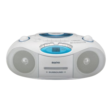
Sanyo DC-MS1 User manual

I1
IFILE NO. I
Service Manual Super Mini Compo- DC-MSI (UK)
nent System (XE)
II ,2% (—FF --) Abl
.—, —.._—... I
Contents
Specification ...........
i
...:..,
129 436 02( UK)
129 436”’04 (XE) :#~L
.................... 1Exploded View(Tape Deck Mechanism) ‘::”::. . . .. . 32
Laser Beam Safety Precaution ................. 1
Operating the Reset Switch . . . . . . . . . . . . . . . . . . . 2
Handling the Pickup . . . . . . . . . . . . . . . . . . . . . . . . . 2
Before Repairing the CD Player ................ 2
Disassembly ............................... 3
Repairing Tool ............................. 8
Disassemble of the CD Mechanism . . . . . . . . . . . . . 9
LCD Block Diagram ........................ 12
Service Mode(CD) ......................... 13
Service Mode(Tape-Deck &Amp) ............. 15
System Contruction of Microprocessors . . . . . . . . 16
CD Adjustments ........................... 17
Tape Deck Adjustments ..................... 19
Tuner Confirms ........................... 21
Exploded View (Speaker Unit) ................ 21
Parts List . . . . . . . . . . . . . . . . . . . . . . . . . . . . . . . . 22
Exploded View(Main Unit) ................... 25
lCVoltage Tableof CD ...................... 29
Exploded View(CD Mechanism) ............... 30
Parts List(CD Mechanism) . . . . . . . . . . . . . . . . . . . 31
ThisServicemanual is consist of’’DC-MSlU”, “RB-MSI”, ”SX-MS1”
Parts List(Tape Deck Mechanism) . . . . . . . . . . . . . 33
Schematic Diagram(Tape Mechanism) .......... 33
lC Block Diagram . . . . . . . . . . . . . . . . . . . . . . . . . . 34
Voitage Table oflC430 . . . . . . . . . . . . . . . . . . . . ..”43
Wiring Connec~on . . . . . . . . . . . . . . . . . . . . . . . . . 44
Schematic Diagram(CD) . . . . . . . . . . . . . . . . . . . . . 46
WkingDiagram(CD) . . . . . . . . . . . . . . . . . . . . . . . . 48
SchematicDiagram(Tuner/TapeDeck Amplifier) .50
WiringDiagram(Tuner/TapeDeck Amplifier) . . . . 52
Schematic Diagram(Front) . . . . . . . . . . . . . . . . . . . 54
Wiring Diagram(Front) . . . . . . . . . . . . . . . . . . . . . . 56
Wiring Diagram(Amplifier-UK) . . . . . . . . . . . . . . . . . 58
Schematic Diagram(Pre-Amplifier-UK) .......... 60
Wiring Diagram(Amplifier-XE) . . . . . . . . . . . . . . . . . 62
Schematic Diagram(Pre-Amplifier-XE) .......... 64
Schematic Diagram(Main-Amplifier) . . . . . . . . . . . . 66
“Dolby” and the double-D symbol ❑are trademark of Dolby
Laboratories Licensing Corporation.Dolby Noise Reduction system
is manufactured under license from Do!by Laboratories Licensing
Corporation.

SPECIFICATIONS
DC-MSI uSUPER hmi SiOMPONENT SYSTEM Amplifier section
Tuner section
Reception frequency ......
CD Player section
Channels ...............
Sampling frequency .......
Pickup .................
Laser output ............
Frequency response .......
Wow and flutter ..........
Cassette deck section
Track system ............
Frequency response . . . . . . .
Signal to noise ratio . . . . . . .
Wow and flutter ..........
Fast forward /
rewind time(approx.) ......
FM: 87.5 -108MWZ
MW: 522-1611 kHz
LW: 144- 2901d-lz
2-channel stereo
44.1 kHz
Optical 3-beam
semiconductor laser
Continuous wave max. 0.6 mW
20 Hz-20 kHz
Below measurable timits
Output power ............
Input ..................
Outclufs ................
General
Power requirements . . . . . . .
Power consumption .......
Dimensions(approx.) .......
Weight(approx.) ..........
25W X2
(at 6ohms, 10 %distortion)
AUX: 470 mV /50 kohms
REC OUT X1,
CD DIGITAL OUT (optical) X1
SPEAKERS: 6ohms
PHONES: 8-32 ohms
AC: 240 V, 50 Hz (For UK)
AC. 230 V, 50 Hz (For XE)
85 W
220(W) X213(H) x261(D) mm
5.4 kg
4-track, 2-channel stereo
60 -14,5 kHz (Cr02 tape) SX-MS1 SPEAKER SYSTEM ‘“
60 -13,5 kHz (Normal tape) Type .................. 2way bass reflex
60 dB (Dolby NR ON) Unit used ............... Woofer: 12 cm cone type
Tweeter: 5cm cone type
0.15 %(WRMS) Maximum power-
110 sec. (C-60) handling capacity ..... 50 W(peak)
Nominal impedance ....... 6ohms’
Dimensions(approx.) . . . . . . . . ‘. 155(W) X206(H) X209(D) mm
Specifications subject to change “without notice.~..~z:.:- -Weight(approx.)’ . . ,~J~:.; ~o.~~.l.8kg (~”r speaker)
..;:._:::.# %*L.., 7‘1’.=--~~
..... . .. ~..<...... .. ..A.- . .,,, .,-,.-.,.,-i. ,,.,,,. . . ::-
., .:-
LASER BEAM SAFETY PRECAUTIONS (CD)
~::’sa’e’y’n’r’ock
Do not look directly at the laser beam cozming from the pick-
up or allow it to strike against your fingers, skin, etc. This model has adisc chuck lever and top lid. This disc
Do not apply power If there IS abroken part In the laser chuck lever and top lid prevent to expose the laser beam for
output section of the pick-up.
INVISIBLE LASER RADIATION EXPOSURE TO BEAM IS DANGEROUS CLASS 1LASER PRODUCT
OUTPUT POWER: 0.6 mW MAX WAVELENGTH :790 nm
m
~rq ,~---
L=ef Output C.ntmu... Wave m=. 06 mW
LaSerleiSw.g: Ungedimpfi. Well. . . . max. 0,6 mw
!%tl. laser: 0,6 mW mui m.ndes .ntrew..,
L.$.wermoge% .Ontinug.N m% 0,6 mw
[G=~:-”7i !
Laa.rubffekt K..ti.u. dig .&g max. 0,6 mW
Lkctin 1.s.. Ond. ma.$inm continua d0,6 mW
.=—–a Sdld. d.1 !6$.. Ond. c.ntin.a mk 0,6 mW
Sdda L.,.. Onda C.nlhw mnx 0,6 mw
,
I
,p.”-
-J (FOR UK)
L 1 IJ
-1-
,...
&
tUSTIO# -IWSSIBLE LASER RADIATION WHEN OPEN A#O T
INTERLOCKS OSFEATEl AVOID EXPOSURC TO BEAM.
ALFVARSEL–EISWlffi LASfR STR LING VEO BNING, N R
SIKKEBHEGSAFSSVOERE ER UOE AF FUNKTIOR, UNOG~ UOS HTELSE
VARUl#G -OSVMIS LASER STR LIIITIG MAR OEIINA OELAR PP#AO
OCH SP,4RR AK uRKGPPLAQ STtiLEM 8S FARL16.
VORSICIIT -wSISHTSARE LASERSIRAllUJ#G TRITT AuS, WETIN
OECXEL GE(WEWET UIIOWES~SICHESHEITSVERSIEGELUNG
UBERllRkST 1SS SISXT. OEM STRAIIL AGSSETZEN.
VARO -AVATSASSSA JA $UOJALUKITUS OHITETTAESSA OLETALTTIWA
NAKYM~TT&kLE lASERSATEILYLLE. all KATSO SATEESEEN, I
(FOR XE)
. .....
.....>”

OPERATING THE RESET SWITCH
This unit is provided with areset switch on the rear panel. The reset switch serves to initialize the microprocessor in the unit
which controls the CD, TUNER, TAPE DECK and AMPLIFIER section. If the unit is to be serviced or key input is not acknowl-
edged even when the CD, TUNER, TAPE DECK, AMPLIFIER and etc. operation buttons are pressad, press the RESET switch
and initialize the microprocessor following the step below.
1)Disconnect the AC power cord from the power outlet.
2) Keep the RESET switch depressed for 60 seconds.
(The backed up electrolytic capacitor is discharged by keeping the RESET switch depress.)
3) Reconnect the AC power cord to the power outlet.
4) Press the CD, TUNER, TAPE DECK, AMPLIFIER and etc. operations, and check their operation.
6
...
HANDLING THE PICK-UP (CD) :
1. Shipping and storage cautions 3)
1) The pick-up must be stored in acoflductive bag until
immediately prior to its use.
2) Do not drop it or subject it to impacts. .4)
2. Repair cautions
1)When handling the pick-up, be careful’ not to give it
undue force or shock by your hands. Otherwise the
pick-tip may malfunction or the PCB may be
cracked.
2) The pick-up which has been minutely adjusted
before shipment as one part. Never touch and move
the adjusting points and setscrews of the pick-up
unless otherwise described in. the item of adjustment
to avoid damage.
Astrong magnet is used in the pick-up.
Do not bring amagnet or other magnetized object
near to it.
Cleaning the lens
●If dust gets on the lens. cJean it away by using an
air brush such as used for acamera lens.
●The lens is held in place by aspring.
If the center of the lens is dirty, carefully clean it
using cotton swab moistened with isopropylalcohol.
Since special coating is made on the surface of the
lens which is made of pbstics, do not use other
kind of alcohol and cleaning fluid to prevent
damage to the lens. Atso, be careful not to bend
the lens spring when cleaning.
BEFORE REPAIRING THE CD PLAYER
1.
1)
2)
Preparations 2. Notes regarding repairs
Many ICS, LSI and the Pick-up (laser diode) are used 1)Be sure to first disconnect the power plug before
in the compact disc player, These components are attempting to replace any component.
sensitive to static electricity, and might be damaged 2) All tools, instruments, etc., used for measuring must
by static electricity or high voltage, so particular care be grounded.
should be taken regarding this point. Grounding can be accomplished by using a
Many precision components and the lens are used in conductive metal sheet on the work bench.
the pick-up. 3) To prevent AV leakage of the soldering iron, ground
Never attempt to make repairs, or to store parts, its metal part.
where the temperature or humidity is high, where 3) Repair personnel must be grounded.
magnetism is strong, or where there is much dust.
-2-
DISASSEMBLY
.Remove the compact disk and cassette tape if there should be one on the disc tray or in the cassette lid.
●Switch the power OFF, and unplug the AC power cord from an AC outlet.
.All wiring should be returned to the original position after work is completed.
1. Side panel
..-,
...—._..___.
2. Top paneI
.-. , ,,,
.: v,-i I.’ ,-. ;..1
.--, . .
3. Tape Deck Mechanism and Cassetie Lid
I
@
,..:.,
-...

4. Front panel
I
P,.
n
,-.....—..
b~ ~~~
‘;, .p\ .“ :::;:,:..’+
‘Q ‘.
5
-..
5. Moving panel Mechanism and Front P. C. Board
.J

DISASSEMBLY
6. Moving panel
@

DISASSEMBLY
8. Pre-amplifier and Tuner/Tape Deck-amplifier P. C. Board
1I
9. Main-amplifier +CD Block
-6-
10. Main-amplifier and CD Block

11. CD Mechanism and CD Main P. C. Board .. . .
.,
,------
*-
t.
/
>

REPAIRING TOOL
●Please use the extension cable for check the P. C. Board.
A
.%.
-@
Extension Cable
No. PARTS CODE INo. PARTS CODE I
-8-
‘ii

DISASSEMBLE OF THE CD MECHANISM
.Do not apply excessive force when handling the pickup, and take extra care not to touch the lens or drive circuit.
●When the disc tray is all the way inside, manually pulling or pushing from behind can lead to damage and should therefore
be avoided. Please follow the correct procedure.
1. Replacing the loading table
(1)
How to remove
lj
2)
3)
4)
Remove the screws @.
Insert afine-pointed screwdriver into the notches on either
side of the fixture @, pry open, then lift upward and remove
by pulling the legs on both sides @.
Move the gears in the direction indicated by the arrow @to
release the pickup’s catch and cause the loading table” (here-
after referred to as the tray) to come out in direction @.
With the tray fully opened, remove the tray by lifting slightly
and pulling forward.
(2) How to insert
‘lj
2)
3)
4)
5)
6)
Push the slide @completely in.
Align the hole in the loading cam gear @with the hole in the
lower chassis.
Align the two projections inside the loading gear Gwith the
dividing rib of the loading cam gear @as shown in the illus-
tration.
With the tray in this position, push in the tray so that the pro-
jections in the loading gear ~align with the groove in the
window in the tray. At this time, align one of the projections in
the loading gear ~with the teeth in the middle of the three
gears visible through the tray window. -
With the front portion of the tray tilted downward about 5de-
grees, slowly push the tray into the mechanism.
Set the fixture in place and screw in the screws @.
2. Disassembly of the mechanism
(1) Removing the pickup block
1)Turn the gear (the above illustration @) in the direction indi-
cated by the arrow and completely lower the sub chassis,
then turn over the chassis. (The fixture does not need to be
removed.)
2) The sub chassis can be removed once the screw @is re-
moved. Removing the screw and washer @makes it possi-
ble to remove the base mechanism chassis.

DISASSEMBLE OF THE CD MECHANISM
(2) Replacing the pickup and applying grease
1)
2)
3)
4)
●
Use the threaded gear @to move the pickup to its maxi-
mum diameter.
Remove the threaded gear by removing the screw that
holds it in place.
Remove the pickup by moving the catches that hold the
pickup rail in the direction indicated by the arrows and
pushing out the rail.
After readjusting or replacing the pickup, be sure to wipe
the pickup rail and apply FLOIL grease (G-474B) to the en-
tire length and diameter. (This should be done each time
the pickup is replaced. Be sure that no grease is applied to
any other part.)
To attach the pickup rail, slide the pickup onto the pickup
rail and push until it hooks on the catches. At this time, ap-
ply asmall amount of “CEMEDAIN” #575 to the area be-
tween the catches and the end of the shaft. (Apply after rail
attachment is completed.)
Next, apply FLOIL grease (G-474B) around the boss of the
threaded gear, then push in the threaded gear while push-
ing the pickup slightly inward.
(3) Replacing the SLED motor .. ! ..
1)
2)
3)
4)
Remove the motor PCB from the spindle motor’ and the
SLED motor.
The threaded motor can be removed and replaced by un-
screwing the two screws that hold it mplace.
Apply grease (EM50L) to the gear teeth of the new thread-
ed motor.
Attach the motor as shown in the illustration.
3Assembling the CD mechanism and applying grease
1)Grease application guide for tray
Apply grease (EM50L) to the areas shown shaded in the illus-
tration.
.-...... . .
@
i!!
-1o-

DISASSEMBLE OF THE CD MECHANISM
2) Grease application guide for loading chassis
Be sure not to get grease on your hands when handling
the loading chassis. Apply grease only to designated
areas of the loading shaft.
Apply grease (EM50L) to the areas shown shaded in the pfi”’’’:!=(,ulul
illustration. ?
REAR FACE
.}
./-- ,:-’” .-
.,., ,, ..-.-,,. ,
--
,. .,. ~
REAR FACE -““’
m“~gj:$::)
INNER SLIT BOTTOM LIBFACE . . . . .. . ... . ,.,, <:,.
3) Grease application guide for base up/down slide
Apply grease (EM50L) to the areas shown shaded in the
illustration.
4) Grease application guide for base mechanism chassis
Apply grease (FLOIL G-474B) to the areas shown shaded
in the illustration.

i
DISASSEMBLE OF THE CD MECHANISM
.The circuitry of the PCB attached to the pickup has been
short-circuited as shown in the illustration to prevent dam-
age from static electricity.
After replacing the pickup, release this short-circuit in the
circuitry and change to the “open” state. ru
(PEN
11
.Precautions when handling the pickup or CD mechanism
1. As the pickup and flexible lead line are easily damaged by static electricity, do not handle with bare hands.
2. Before shipping the CD mechanism, place in an antistatic bag, move the pickup to the innermost position, and set to the
chucking state (in which the turntable is up). Before shipping the pickup, short-circuit the circuitry on the PCB and attach
the lens cover in order to protect from static electricity.
LCD (LIQUID CRYSTAL DISPLAY)
m
SEG 0123
COM3 4321
........ .... ... ........
COM2 8765
........ .... ... ........
COM1 12 11 10 9
........ .... ... ........
COMO ➤15 14 13
4 5 6 7 8 9 10 11 12
pkHz 9d MHz 8d SIDEB C REC 7d SIDE)
. .. . .. .. ... . .. . .. ... .,. . ... .. .. ............ .......
PROG 9C 9e EC 8e
. ..... ... .. . . . .... . .. ... .. ... . .. ... .. ..-. .
PM 9b 9g 8b 8g :7b
. .. .... .. .. . . . .. . . ... .. .. . ....
AM 9a 9f 8a 8f
-J L_wlL
Y_ I--
13 14 15 16 17 18 19 20
6d MONO STE 1-v AM ALL 4d
REO
............ . . . . . . . . . . . . . . . . . . . . . . . . . . . . . . . . . . .
6e 5g Lw 1(FM) MW 4C 4e
... .. .. .. ... .. .. . . .... .. .. .. .. .. .. . .. . . .... ..
6g 5bc 2(FM) CLOCK FM 4b 4g LEVEL
.. .. .. ..... . .. . . . .... .. .. .. . ... . . . ... .
61 TIME ‘AN O- ON da 4f REC
DOM
>
-12- Tt
21 22 23 24
TRACK 3d ONE 2d
. .. . .. . . .. . ... .......
3C 3e 2C 2e
,. . . . . . . . .. . ... .......
71b 3g 2b 2g
. . . . .. . . .. . ... ..... ..
3a 3f 2a 2f II
25 26
SLEEP REP
EAT
........ .......
lbc Id
........ .......
Iafe lh
.... .... .......
WAKE T,MER
UP

SERVICE MODE (CD)
Specifications
To enter any service mode other, first simultaneously press the CD TRAY and REPEAT keys on the unit. This accesses the
service mode entry state. Now press one of the buttons on the unit to enter aservice mode. As the service mode entry
\
state is discontinued after 1second ela S:S, the system will enter aservice mode only if the next key is pressed within one
second. ~Co’’p./<r &.<
1. Checking the key input signal connections
“After powering on the unit, press the COMPUTER REC key from service mode entry Status to enter this mode.
~Once this mode is activated, the tray and panel LEDs light, and all LCD segments are also displayed.
.In this mode, each press of the COMPUTER REC key toggles the LEDs and LCD segments between all on and all off
status.
.In this mode, pressing any of the keys listed in Table 1causes the corresponding LCD segment listed to go on. (Start
with all segments off in order to confirm the proper operation of the keys and display segments.)
.The mode is released when the power is turned off.
IKEY iDISPLAY IKEY !DISPLAY IKEY IDISPLAY IKEY IDISPLAY [
~IAUX ImICDTRAY Inl
MEMORY nRANDOM mr11
SET /CLEAR mREPEAT mICD PLAY aPANEL is
CLOCK HSLEEP ❑!Il TUNER/BAND PROG.
TIMER EI I I I
WAKE UP HEDIT ii i pAM
I I
1DOWN iI- 1 1
mITIME Imup mtTAPE PM I
mSTOP m
TABLE 1: Corresponding keys and displays in the key checking mode
TIMER REC ON OFF RANDOM PROG D
WAKE UP LEVEL CLOCK TIME EDIT AM mnmmm
‘1-1 1-1 1-1/:/ ~~:v I1-1n ●n 1-1 ;[ ;;:;
\_/ /:/ /://_\ AM Lw ‘/ /://-/●/–/1–/ MHZ ~~~m
-0-—
SLEEP TRACK STEREO SIDEA SIDEB
REPEAT ONE ALL MONO COMPUTER .REC (~) DOLBYNR
FIGURE 1: The upper part of LCD (Liquid Crystal Display )
2. CD tracking balance adjusting mode
“Press the EDIT key from service mode entry status to enter this mode.
“When this mode is activated, the function becomes CD. When the unit is powered off, it automatically powers on again.
“In this mode, the unit automatically enters tracking balance adjustment status (tracking off) after the tray closes. In this
status, the tracking servo turns on when the CD PLAY key is pressed and play begins from that place. (If the location is
the lead-in area, “TNO =00” and “E.TIME” are displayed and play starts.) Consequently, the initial position of the pickup
(the limit switch position) can be determined from the display when play starts.
“In this mode, pressing the EDIT key during play activates tracking balance adjustment status. In this status, the tracking
servo turns on when the CD PLAY key is pressed and play begins.
“In this mode, play does not stop even if aservo error occurs.
.In this mode, power to the CD circuitry is not cut off when the CD stops (to allow for focus offset adjustment).
“The mode is released when the power is turned off.
-13-

“i
SERVICE MODE (CD)
3. CD operation display mode
Press the TIME key from service mode entry status to enter this mode.
When this mode is activated, the function becomes CD. When the unit is powered off, it automatically powers on again.
In this mode while the function is CD, the LCD display shows special indications, different from the normal display, that
show the CD operations. (See Table 2 and Table 3.).
In this mode, acalendar number of the sort shown in Table 4appears if aCD error occurs. Also, the CD operation display
and calendar display freeze from the point at which an error occurs onward. The display can be “unfrozen” by pressing
the STOP key when the CD is stopped.
.The mode is released when the power is turned off
ITRACK No. IMEANING I
1IStop in progress
2IPlav in oroaress
13 IFast forward toward outer edae in rxo~ress ]
14IFast forward toward inner edge in progress I
TRACK No. MEANING
5Pause in progress
6Tray open in progress
7Tray close in progress
8TOC read in progress
TABLE 2: DISPLAYS DURING THE CD OPERATION MODE (OUTLINE =TRACK No. PART)
ITRACK IMIN. ISEC. IMEANING
dle break in progress
110Spire
120Pickup return ‘- ‘v--”-”- 11
TRACK MIN. SEC. MEANING
3 1 0Fast forward toward outer edge in
oroaress (16-track iumo)
“““’”y’”””------i
tI11,“. . .
3!2 O IFast forward toward outer edge in I
1+-R--R‘“n”““’’’’;*”’””
Iw.vy, .,- “.- ..”.,.-.,
I
L i dlPlay start
212 0IFocus search in progress
1#,
2]3 OlSpindle kick in progress
1I(compulsively accelerate) I
I2I4IOlSona access start (oosition check) I
I1tI. .
2[4111- Song access (quick access) 1
I2\4I2lSong access I
Ill I(oosition check after auick access) I
progress (subcode read)
40 0 Fast forward toward inner edge start
410Fast forward toward inner edge in
progress (16-track jump)
4“2 oFast forward towardhm~?:edge in
oroaress (subcode read)
50 0 Pause in progress (1-track jump)
5 1 0Pause in progress (trace)
1.,
24 3 Song access (outer edge 64-track jump) 6‘oStop processing in progress with tray
24 4 Song access (inner edge 64-track jump) open
2460
5Song access (outer edge 16-track jump) ~o0Tray open in progress
246Song access (inner edge 16-track jump) ~o0Tray close in progress
24 7 Song access (inner edge 1-track jump) oPickup return in progress
250Song access (subcode read) 81 0 Focus search start
260Play in progress 8 2 0Spindle kick in progress
20 0 Play in progress (compulsively accelerate)
8 3 0Subcode read
30 0 Fast forward toward outer edge start 8 4 0TOC read in progress
TABLE 3: DISPLAYS DURING THE CD OPERATION MODE (TRACK No., MINIT &SECOND PART)
No. STATE OF CD ERROR No. STATE OF CD ERROR
Good 5The subcode is not input while the servo is on.
1Focusing is not possible in focus search. 6Tray open cannot complete.
2The subcode is not input during disc startup. 7Tray close cannot complete.
3TOC cannot be read. 8Panel open cannot complete.
4The focus was lost while the servo was on. 9Panel close cannot complete
TABLE 4: DISPLAY OF CD ERRORS (MUSIC CALENDER No. PART)
-14-

Ii
SERVICE MODE (TAPE DECK &LIFIER)
Specifications
Hold down the DISPLAY, BASS and POWER keys when powering down the unit. Set the function to TAPE.
1. Checking the key input signal connections
.Pressing any of the keys listed below causes the corresponding LCD segment or LED to turn on or off.
KEY IDISPLAY IEFFECT 1] KEY
+%--w-i
DISPLAY LCD /LED ALL ON /OFF SOUND
DCINR LCD DOLBY NR ON /OFF
MODE LCD ~;-:> ON /OFF LIVE /ON
STOP LCD SDISPLAY ON /OFF STAGE#
REC LED REC ON /OFF ECHO
REC MUTE# LED REC MUTE#
FLASHING /OFF
FPLAY# LED ➤ON/ OFF CD
4PLAY# LED +ON /OFF TAPE
PLAY LCD PDISPLAY ON /OFF TUNER
FAST FWD LED ➤FLASHING /OFF AUX
FAST REV LED <VOL +#
FLASHING /OFF
BASS LCD -ON/ OFF VOL –f
Keys with #ma
=4%--KM
LCD TUNER ON 10FF
LCD AUX ON/ OFF
LCD UDISPLAY ON /OFF
LCD DDISPLAY ON/ OFF.
have on remocon ..-. ~..—. .
TABLE 5: Corresponding keys and displays in the key checking mode .-.,.
Vlvlo-
(GAME)
MILD
VOCAL
NORMAL
—
[LIVE “1
--
--
——
——
--
——
--
--
—-
——
-MAX
—
—
—
---
—---
--—
—--—
-—-
————
-——
—--—
———
————
--—
————
—-—
————
--—
—-——
--
--
--
——
--
-—
--
--
--
——
--
-—
--
——
--
-—
1 J
ON
STAGE -
-
-
EEEm
mEl
--
--— — mm
m
--
—- —
—
-—
-— IMIN U!!Ll60 150 400 lk 2.4k 6k 15k VOL
FIGURE 2: The lower part of FL (Fluorescent Display )
2. Tape-Deck Service Mode
(1)
Activating the service mode
~Short the short-point of the pre-amplifier p. c. board.
.The mode is released when the power is turned off.
1
I
R4372 560 M38062M3
---
\
—\SHORT POINT —
SHORT POINT PRE-AMPLIFIER P. C. BOARD

SERVICE MODE (TAPE DECK &LIFIER)
(2) Description of tests after entering the service mode
In this mode, the spectrum analyzer functions as acounter display (00 +FF +00 --”--). In this mode, REC only works
with FWD. (The REV key has no effect when pressed from ret/pause status.) In this mode, the AMSS function does not
operate. It is replaces by normal cue/review operation.
1)
2)
3)
4)
5)
6)
7)
8)
9)
1o)
11)
Insert atape and press the RECORD key. The function switches to AUX, with recording bias on and rec mute off, and
the motor turns on. (The plunger does not function.)
Pressing the PLAY/PAUSE key from the above status causes the unit to switch to record status and resets the
counter. The reel pulse counter starts 0.5 seconds after the mechanism’s PLAY switch is turned on. The counter
value is displayed on the LCD.
Pressing the STOP key is the above status causes the function to switch tot tape.
Then, 0.5 seconds after the mechanism’s R/F switch is turned off, reel pulse counter stops.
Rewind starts immediately thereafter and the tape is would back the same number of reel pulses that have elapsed
since recording started. The status then changes from stop to play and the portion of the tape that was just recorded
is played. The counter display operates during the above.
If the tape was rewound too far, those reel pulses are counted negatively.
The unit remains in play status for the same number of reel pulses that elapsed during record status.
After the number of reel pulses that elapsed during record status have
Operations 7. and 8. are repeated until the STOP, FF or REW key is pressed:
Pressing the FF or REW key while the operations described above are taking place initiates the cue/review function,
after which the~e are,,norepetitions of the above operations.
,,.
Pressing the STOP key puts the units into stop status. after which there are no repetitions of the above operations.
SYSTEM CONSTRUCTION OF MICRO PROCESSORS ... .. . . .
. . . .. ,:,. .
.’ ”-.’ ‘“’, ”~,.,-.
-16-

CD ADJUSTMENT
Electrical Adjustment 10K
T;; ~“
So far we have presented explanations regarding compact
disc player handling, notes prior to repair, handling the pick-
up and disassembly of the unit. Be sure to carefully read ,,43:’]”..’’’.-’.0. ‘
these instructions before making any adjustments. BAND PASS FILTER
Preparations for Adjustments
Measuring instruments, tools and filter (4) AF oscillator (400 Hz, 300mV RMS)
(1) Test disc. :YEDS 18 (Sony) (5) Frequency Counter (5MHz ;or more)
(2) Oscilloscope :SS5711 (1OMHZ or dual phenomenon) (6) Screw drivers (non metalic) for adjustments
or Memory scope :DSS6521 (Storage scope) (7) Band Pass Filter (See fugere)
(3) Digital voltmeter (Input impedance 1Mohm or more) (8)AC Voltage Meter
Notes :a. The adjustments can be using the equipment produced by other manufactures provided that the performance of
that equipment corresponds to that of the above listed models.
b. Use a10:1 probe for observing signals on the oscilloscope and storage scope.
c. Test disc is subject change without notice.
1. Initial set up
Set the SVR11 at its initial position of adjustment TEST POINT(CN114)
controls as shown in figure below.
..... . .. .. -..,.. . . . . . . . .. .. ..
.’ ...,. ,.. . ~~ =WSVR1’
III”
Ii
... SVRI1 ... ,“..”- .: :_~,, -, ,,. ,; -.:7 --.,,;;,
INITIAL SET “
..._.(MECHANICAL .CENTER) / . WI
/~~ ‘----- ------ --- -----—- 1
CD MAIN P. C. BOARD
““[’
[
.-
1,
....
.,
\
2. Tracking Balance Adjustment (SVR11)
1) Connect the oscilloscope to TP3 (TE) and TP4 (VC).
2) Turn on the power of the unit. Insert test disc .
3) Insert test disc. And set the function to CD position.
4) Push the CD TRAY button and REPEAT button at the TP1
same time. Soon after, push the EDIT button within a(RF)
second.
‘See to Service mode (Tracking balance adjustment mode)
5) Adjust SVR11 so that the TE (Tracking Error) signal
waveform of TP3 on the oscilloscope is vertically sym-
metrical relative to VC. (See figure right side) TP3
6) The mode is released when the power is turned off. (TE)
‘If the adjustment is imperfect, become run away the sled
motor (pick-up sending motor), inferior playability.
-17-
Vc
...’....
....’...........:., .-

CD ADJUSTMENT
3. Other Adjustment of Tracking Balance (SVRll)
1) Connect the oscilloscope to TP3 (TE) and TP4 (VC). 5) Continuously press the forward search Mor backward
2) Turn on the power of the unit. search 44 button to do it.
3) Load the Test disc. And set the function to CD position. 6) Adjust SVR11 so that the TE (Traverse) signal waveform
4) Playback the Test disc. of TP3 on the oscilloscope is vertically symmetrical rel-
ative to VC.
TP 1
(RF)
TP3
(TE)
44 SEARCH
4. Focus Gain Confirmation
Vc Vc
SEARCH W
1) Connect the storage scope to TP2 (F.E :Focus Error) 4) Set the output of AF oscillator to 400 Hz, 0.5V rms and
through the Band pass filter. (See BPF Figure) connect to pin 24 (ICI 01)through the resistor :10Ok
2) Turn on the power of the unit. ohms.
3) Play-back the test disc.
“If this CONFIRMATION is
Disc.
AF OSCILLATOR
5) Confirm so that the voltage of the F.E signal waveform
on the storage scope is 0.5V p-p, t3db by through
BPF.
,.
imperfect, become weak the mechanical shock, inferior playability, and can not playback the
MAIN PCB OSCILLO SCOPE or STORAGE SCOPE
,
400Hz lOOK BAND PASS FILTER
IClol TP2
0.5V rm5 PIN 24 (FE)
TP4 (VC) Iuq
I
5. Tracking Gain Confirmation
1) Connect the storage scope to TP3 (T,E) through the 4) Set the output of AF oscillator to 400 Hz, 0.5V rms and
Band pass filter. (See BPF Figure). connect to pin 14 (IC101) through resistor 56k ohms.
2) Turn on the power of the unit. 5) Confirm so that the voltage of T.E signal waveform on
3) playback the test disc. the storage scope is 0.5V p-p, t3db by through BPF.
●If this CONFIRMATION is imRerfect, become weak the mechanical shock, inferior playability, and can not playback the
Disc.
AF OSCILLATOR
Iclol TP3
PIN 14 (TE)
TP4 (VC)
I
MAIN PCB OSCILLO SCOPE or STORAGE SCOPE
=

TAPE DECK ADJUSTMENT
1. Amplifier Adjustment
IITEM ]TESTTAPEI INPUT IDOLBY IOUTPU7
1Head Azimuth VIT-738 OFF TAPE
OUT
2Tape Speed MTT-lll N-OFF TAPE
OUT
Playback
3TCC-130 OFF TAPE
Level OUT
Rec /Play AUX IN
4AC-224 lkHz /l OkHz ON TAPE
Frequency -31dB OUT
ADJUST POINT REMARKS
Azimuth Screw IAdjust so as 10kHz output become maximum.
Adjust SVR so as 10kHz output become
SVR40 maximum.
SVR31 (L-ch)
SVR32 (R-ch) Adjust so as TAPE OUT output become 0.58V.
SVR35 (L-ch) R/P signal, set frequency characteristic 1kHz
SVR36 (R-ch) output to OdB. Adjust SVR so as 10kHz output
become ~OdB.
Note: During alignment, measurement Beat cancel switch is at 1condition fundamentally, confirm Ret/Play frequency charac-
(1)
●
●
●
●
1)
2)
3)
4)
5)
teristic, dolby effect also by 2condition,
Head azimuth adjustment
Be sure to clean the heads before attempting to make any adjustment.
Be sure both channels waveform are same for the phase matching.
Be sure both channels (1 and 2) are the same level. (Using adual-channel oscilloscope.)
After completion of the adjustment, use the threadlock (TB-1 401 B) to secure the azimuth adjustment screws.
Load a test tape. (VTT-738 etc, :10kHz)
Press the PLAY button. FOWARD
h
REVERSE
Use a+;screwdriver to turn the screw for forward azi- ‘-- T~. -:
muth adjustment so that the left and right outputs are ,.’
maximized at the same phase during forw;rd playback.
Playback the tape in the reverse mode.
Use aflat-tip screwdriver to turn the-screw for reverse
azimuth adjustment so that the left and right outputs are
maximized at the same phase during reverse playback.
(2) Tape speed adjustment
●
1)
2)
3)
4)
4.
Make the adjustment near where the test tape finishes winder.
Connect the FREQUENCY COUNTER to TAPE OUT.
Insert the test tape(MTT-111 N, etc. :3000 Hz)”into the DECK .
Press the FWD PLAY button.
Use a+screwdriver to turn the SVR40 to adjust so that the frequency counter became 3000 t5Hz.
Press the STOP button, and eject the test tape.
2. Parts Location
SVR LO
TAPE SPEED ADJUSTMENT
I
‘Y–/~
EIEAT SWITCH
s3601 ~j~;l ‘REQUENCV ‘OJusTMENr TUNER/ TAPE DECK AMPLIFIER P.C.B
-19-
)-
PRE-AMPLIFIER P.C.B
Other manuals for DC-MS1
1
Table of contents
Other Sanyo CD Player manuals

Sanyo
Sanyo CDP-S4900 XE User manual

Sanyo
Sanyo mcd-z37f User manual

Sanyo
Sanyo CDP-4000 User manual

Sanyo
Sanyo CDP-360 User manual

Sanyo
Sanyo CDP-865 User manual

Sanyo
Sanyo MCD-Z160F User manual

Sanyo
Sanyo CDP-M420 User manual

Sanyo
Sanyo DV-S100 User manual

Sanyo
Sanyo MCD-Z11F User manual

Sanyo
Sanyo FXD-RS60R User manual

Sanyo
Sanyo CDP-4100CR User manual

Sanyo
Sanyo MCD-Z250F User manual

Sanyo
Sanyo FXD-CI00 User manual

Sanyo
Sanyo MCD-Z150F User manual

Sanyo
Sanyo MCD-S735F User manual

Sanyo
Sanyo FXD-C200 User manual

Sanyo
Sanyo MCD-ZX530F User manual

Sanyo
Sanyo CDP-4000 User manual

Sanyo
Sanyo CDP-360CR User manual

Sanyo
Sanyo CDP-MT500 User manual