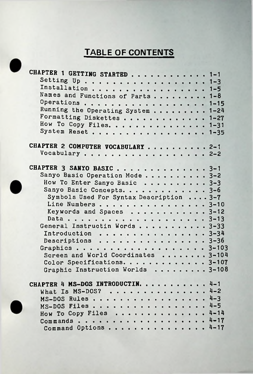
Sanyo MBC-550 Series User manual

».
.
■v
-
0000000
'
k
>■
c-
;.
•
■
H
■Tv.;;-
j
1;
■.
i
N\
N
.
m
y
M
|te
v
;
r
coocwo
A
■
m
/
■
[•
OOOO
.
*
.
I
y
.
■
••
:
.
i'
AviV-i
.

MBC-550
SERIES
USER
’
S
GUIDE
@
SANYO


PREAFACE
Please
read
this
manual
thoroughly
before
you
begin
to
install
and
use
Sanyo
MBC-550
series
computers.
ll
rights
reserved.
No
part
of
this
manual
may
be
reproduced
in
any
form
without
expressing
written
permission
form
Sanyo.
If
The
contents
of
this
manual
are
subject
to
change,
you
wish
to
receive
revisions
and
u dates,
lease
contact
the
lace
of
urchase.
Sanyo
assumes
no
res onsibilities
for
errors
in
this
manual
or
their
consequences.
MS-DOS
is
a
trademark
of
Microsoft
Cor oration.


o
m
3
0)
(
a

"O
<
(0
CO
O)
c
+=
0

T BLE
OF
CONTENTS
CHAPTER
1
GETTING
STARTED
.
.
.
Setting
Up
...............................
Installation
...........................
Names
and
Functions
of
Parts
Operations
...............................
Running
the
Operating
System
Formatting
Diskettes
.............
How
To
Copy
Files
....................
System
Reset
...........................
1-1
1-3
1-5
1-8
1-15
1-24
1-27
1-31
1-35
CHAPTER
2
COMPUTER
VOCABULARY
Vocabulary
...........................
2-1
2-2
CHAPTER
3
SANYO
BASIC
....
Sanyo
Basic
Operation
Mode
How
To
Enter
Sanyo
Basic
Sanyo
Basic
Concepts.
.
.
Symbols
Used
For
Syntax
Description
....
3-7
Line
Numbers
................................
Keywords
and
S aces
....
Data
.........................................
General
Instructin
Words
.
.
.
Introduction
........................
.
Descriptions
...........................
Graphics
.....................................
Screen
and
World
Coordinates
Color
Specifications
.............
Graphic
Instruction
Worlds
3-1
3-2
3-3
3-6
3-10
3-12
3-13
3-33
3-34
3-36
3-103
3-104
3-107
3-108
4-1
CHAPTER
4
MS-DOS
INTRODUCTIN
What
Is
MS-DOS?
.................
MS-DOS
Rules
.........................
MS-DOS
Files
.........................
How
To
Co y
Files
....
Commands
.................................
Command
Options
.............
4-2
4-3
4-5
4-14
4-17
4-17

4-18
4-18
4-20
Single
Drive
Users
.......................
Information
Common
To
all
Commands
Control
Character
Functions
....
CHAPTER
5
TECHNICAL
REFERENCE
.
.
.
Specifications
...........................
Character
Codes
........................
List
Of
Reserved
Words
.............
Sanyo
Basic
Error
Message
List
Disk
Error
Messages
....................
Memory
Map
..................................
ROM
Map
......................................
Interrupt
Vector
.......................
I/O
Interrupt
Controller
8259
Interrupt
Routines
...................
Keyboard
Translation
Table
.
•
I/O
Map
.....................................
8255
PPI
I/O
Map
....................
US RT
8251
...............................
Keyboard
Signals
........................
Key
Operation
...........................
Timer
...........................................
Baud
Rate
Establishing
................
Video
RAM
and
HD46505
CRTC
.
.
DTS-4
Di
Switch
..............................
DOS
Editing
Keys
..............................
5-1
5-2
5-3
5-6
5-8
•
5-12
.
5-14
.
5-15
.
5-16
.
5-17
•
5-19
.
5-28
.
5-30
5-31
5-32
5-33
5-33
5-36
5-37
5-38
5-40
5-41
6-1
CHAPTER
6
PERIPHERAL
INSTALLATIONS.
.
.
Installation
Instructions
............
.
Cabinet
Cover
Removal
................
.
.
Rear
Panel
Removal
..............................
Second
Drive
(FDD
1655)
Installation
Memory
Expansion
(MBC
64K)
Installation
.
.
.
6-10
Serial
Port
(MBC
232C)
Installation
Joy
Stick
Installation
...................
Monitor
(CRT-36)
Installation
.
.
.
dditional
Software
and
Manuals
.
.
6-2
6-3
6-4
6-6
6-15
6-19
6-21
6-22

INDEX
.
1-1


••
CHAPTER
1
GETTING
STARTEO
1-1

INTRO UCTION
The
MBC-550
series
com uter
is
16
bit
com onent
ty e
ersonal
com uter.
It
features
an
Intel
8088
(3.6
MHz
no-wait)
central
rocessing
unit
(CPU).
The
main
128K
memory
may
be
ex anded
u
to
256K.
The
MBC-550
series
com uter
comes
wih
a
standard
5
1/4
inch
single-sided,
double
density
flo y
disk
drive
(160K
bytes
in
its
formatted
state).
An
additional
drive
may
be
added.
High
resolution
color
or
monochrome
monitors
may
be
used
with
your
com uter.
The
color
monitor
is
14
”
640
x
200
dots
one-dot-eight-color
ty e
and
the
green
monitor
is
12"
640
x
200
dots
ty e.
We
recommend
Sanyo
brand
monitors
for
the
best
results.
The
o erating
system
used
is
MS-DOS
(tm)
by
Microsoft
(tm).
A
wide
range
of
software
and
a lications
is
available.
Please
contact
your
authorized
Sanyo
com ut
er
dealer
for
more
information
on
these
rograms.
The
MBC-550
series
com uter
has
a
arallel
rinter
that
allows
com atibility
with
Sanyo
brand
rinters
as
well
as
most
arallel
rinters.
An
o tional
RS-232C
inter
face
is
available
for
connections
with
serial
rinters.
1-2

SETTING
UP
Computer
Location
The
lacement
of
your
Sanyo
com uter
is
im ortant.
Just
as
you
would
not
lace
your
refrigerator
near
the
furnace
work
with
maximum
efficiency.
Please
follow
these
guide
lines
in
selecting
a
suitable
lace
for
your
com uter.
Do
not
lace
the
com uter
in
the
direct
sun
light
or
near
heaters
or
coolers.
you
should
locate
your
com uter
where
it
will
1.
2.
Do
not
locate
the
com uter
in
areas
of
dirt
and
dust
or
where
vibration
may
take
lace.
3.
Do
not
use
in
areas
of
intense
electromagnetic
fields.
4.
Kee
the
com uter
away
from
walls
and
lace
it
in
a
well
ventilated
room.
5.
Use
only
specified
local
power
lines.
6.
Do
not
drink
or
eat
near
the
com uter
or
lace
it
where
crumbs
and
liquid
can
enter
the
com uter
cabinet.
1-3

D skette
Handl ng
Do
not
in
or
cli
the
diskette
(disk)
jacket.
Do
not
write
anywhere
on
the
disk
exce t
on
the
label.
Always
write
with
a
felt
ti
en;
do
not
use
a
encil
or
ink
en.
Do
not
touch
the
magnetic
re
cording
face.
Never
clean
with
alcohol
or
similar
material.
Never
ex ose
disks
to
magnetic
or
electric
fields.
Do
not
store
disks
in
direct
sunlight,
extreme
heat
or
cold.
Kee
the
diskettes
inside
their
envelo es
to
rotect
against
dust
or
dirt.
Do
not
bend
or
fold
diskettes.
Always
make
co ies
of
original
disks
for
safe
kee ing.
Recommended
D skettes
Sanyo
recommends
the
use
of
the
Sanyo
MD1DD
diskettes
(single
sided,
double
density,
soft
sectored).
Sanyo
assumes
no
res onsibility
for
trouble
arising
from
the
use
of
other
diskette
ty es.
1-4

INSTALLATION
Use
local
AC
ower
outlets,
switching
the
ower
on
or
off.
Remove
diskettes
before
System
Co ectio
Please
read
the
following
instructions
before
connect
ing
the
system.
Check
each
box
[]
as
you
complete
each
step.
Connect
the
keyboard
as
shown
below.
RE R
P NEL
KEYBO RD
©
/
[]
Remove
the
vinyl
cover
from
the
lugs
and
connect
ors.
[]
Join
the
keyboard
cable
to
the
com uter
socket
labeled
KEY
BOARD.
1-5

Mon tor
Connect on
Sanyo
CRT-36
Data
Dis lay
Monitor
The
CRT-36
monitor
may
be
laced
on
the
to
of
the
com uter
cabinet
or
in
a
convenient
location
nearby.
[]
Connect
the
video
cord
to
the
monitor
in
the
rear
socket
labled
VIDEO
OUTPUT.
[]
Connect
the
other
end
to
the
rear
of
the
Sanyo
550
series
com uter
in
the
socket
labeled
MONO
CHROME.
[]
Connect
the
ower
cord
to
a
local
outlet,
ower
switch
is
located
below
the
screen.
The
OTHER
MONITORS
-
SOME
MONITORS
PROVIDE
POOR
NOTE:
FOR
EMI
PERFORMANCE.
CONNECT
THE
MONITOR
POWER
CORD
TO
THE
MBC
550
SERIES
COMPUTER
POWER
OUTLET
LOCATED
IN
THE
REAR
OF
THE
COM-
TO
ELIMINBATE
THE
NOISE
PROBLEM,
PUTER.
Printer
Connection(optional)
Parallel
Printers
Connect
the
rinter
as
shown
below.
REAR
PANEL
PRINTER
SPRING
1-6

[]
Connect
the
rinter
cable
to
the
com uter
connector
labeled
PRINTER.
Lock
by
ressing
s rings
into
the
slots
on
the
rinter
lug.
Note
that
this
is
a
arallel
(Centronics)
rinter
ort
and
will
su ort
only
a
arallel
rinter
such
as
the
Sanyo
PR5000/
5500.
Please
contact
your
Sanyo
com uter
dealer
for
other
Sanyo
rinters.
[]
Connect
the
rinter
cable
to
the
rinter.
CAUTION:
When
connect ng
per pherals
to
the
MBC-550
series
com uters,
be
sure
to
use
the
s ecified
shield
cables
(by
the
eri herals*
manufacturers)
to
meet
the
FCC
regulations.
1-7

N MES
ND
FUNCTIONS
OF
THE
P RTS
Names
Front
71
(2)
Drive
Lamp
\
i
(D
Diskette
Set
Lever
A
(4)
Diskette
Case
(B)
Keyboard
(T)
Power
Switch
(3)
Floppy
Disk
Drive
1-8

Funct ons
1
Power
Switch
Press
the
switch
in
to
turn
the
com uter
on.
A
red
light
will
glow
on
the
A:
drive
indicating
full
ower.
Never
turn
the
ower
on
with
a
diskette
in
the
drive.
2
Drive
Lam
This
red
lamp
glows
when
power
is
first
turned
on
and
indicates
full
power
received.
With
two
drives,
the
drive
lamp
indicates
which
drive
is
being
used.
3
Floppy
Disk
Drive
This
is
a
built-in
5
1/4"
single
sided,
double
density,
floppy
disk
drive.
One
more
drive
may
be
added
in
the
space
now
used
for
diskette
storage.
4
Diskette
Case
This
compartment
may
be
used
to
store
disks.
Please
note
the
position
of
the
diskette
as
it
enters
the
compartment.
Do
not
force
entry,
try
again
with
disk
rotated
till
it
matches
the
figure
in
the
illustration.
5
Diskette
Set
Lever
Insert
the
diskette
into
the
drive
and
move
the
lever
down
to
set
the
diskette.
Move
the
lever
up
to
remove
the
diskette.
Never
start
the
computer
with
the
diskette
in
the
drive.
6
Keyboard
The
keyboard
contains
ten
function
keys,
cursor
control
keys,
numeric
keys,
ten
key
pad,
math
function
keys,
and
editing
keys
in
SCII
specifications.
1-9
Table of contents
Other Sanyo Desktop manuals
Popular Desktop manuals by other brands

maximatecc
maximatecc CrossCore XM Software guide

HP
HP 742n - Pavilion - 512 MB RAM Specifications

Dell
Dell OptiPlex 7050 Small Form Factor owner's manual

Medion
Medion PC TITANIUM MD 8000 Getting started guide

HP
HP Compaq Presario Getting started guide

GÜNZBURGER STEIGTECHNIK
GÜNZBURGER STEIGTECHNIK FlexxTower 125100 manual