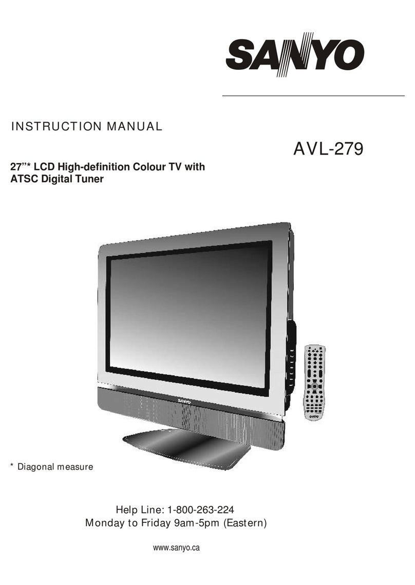
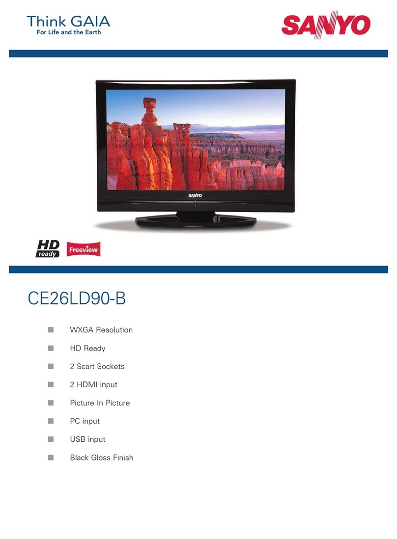
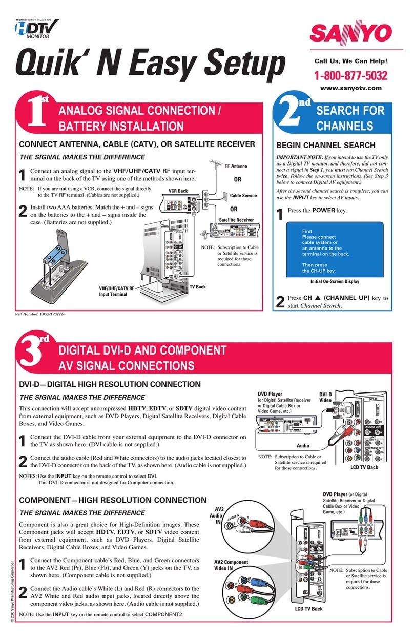
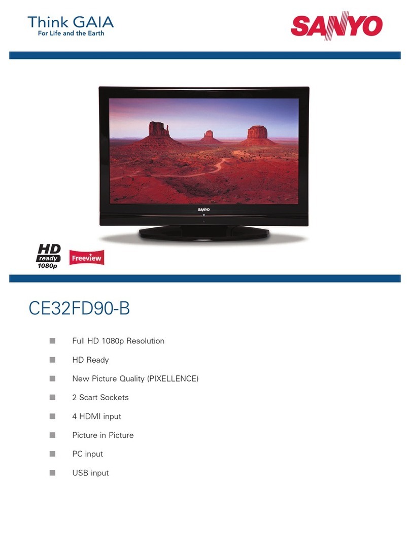
Sanyo 263 User manual

26” and 32"* LCD High-definition Colour TV with
ATSC Digital Tuner
INSTRUCTION MANUAL AVL-261/263/
321/323
Help Line: 1-800-263-224
Monday to Friday 9am-5pm (Eastern)
* Diagonal measure
www.sanyo.ca
For best TV picture quality and channel selection connect to a digital
cable or satellite receiver

Important Information .......................................................................................................................................................1
Important Safety Precautions...........................................................................................................................................2
Setup................................................................................................................................................................................5
Identification of Controls...................................................................................................................................................7
Connections....................................................................................................................................................................10
Basic Operations............................................................................................................................................................14
Memorizing the Channels...............................................................................................................................................15
Channel Selection..........................................................................................................................................................17
.............................................................................................................................................21
Viewing Closed Captions
Setting Parental Control
Troubleshooting.............................................................................................................................................................28
Care and Maintenance...................................................................................................................................................29
Specifications.................................................................................................................................................................30
Programming the Universal Remote Control.................................................................................................................31
Screen Set-up for inputs other than Component............................................................................................................18
Screen Setup for Component Mode ..............................................................................................................................19
Setting Sound ................................................................................................................................................................20
Time Set and Sleep Timer
...............................................................................................................................................22
.................................................................................................................................................23
Table of Contents
ThankyouforchoosingSANYO.Thisproductincorporateslatest-generationfeaturesincluding
an ATSC digital tuner. Please read all instructions carefully to obtain maximum benefit of your
product. Questions? Our toll-free number is 1-800-263-2244, 9am-5pm, Monday to Friday
(Easterntime).

WARNING: TO REDUCE THE RISK OF FIRE OR ELECTRIC SHOCK, DO NOT EXPOSE THIS APPARATUS TO RAIN OR
MOISTURE.
The lightning flash with arrowhead symbol,
within an equilateral triangle is intended to
alert the user to the presence of uninsulated
dangerous voltage within the product's
enclosure that may be of sufficient magnitude to
constituteariskofelectricshocktopersons.
The exclamation point within an equilateral
triangle is intended to alert the user to the
presence of important operating and
maintenance (servicing) instructions in the
literatureaccompanyingtheappliance.
RISK OF ELECTRIC SHOCK
CAUTION
CAUTION-To reduce the risk of electric shock, do not perform any
servicing other than that contained in the operating
instructionsunlessyouarequalifiedtodoso.
Thisproductutilizestin-leadsolder,andfluorescentlampcontainingasmallamountofmercury.Disposalofthesematerialsmayberegulateddue
toenvironmentalconsiderations.Fordisposalorrecyclinginformation,pleasecontactyourlocalauthoritiesortheElectronicIndustriesAlliance:
www.eia.org
FCC STATEMENT
FCC Notice
LCD TV: A CLASS B digital device
ThisequipmenthasbeentestedandfoundtocomplywiththelimitsforaClassBdigitaldevice,pursuanttopart15oftheFCCRules.These
limits are designed to provide reasonable protection against harmful interference when the equipment is operated in a commercial
environment.
Thisequipment generates,uses,and canradiateradio frequencyenergy and,ifnot installedandused inaccordancewith theinstruction
manual, may cause harmful interference to radio communications. Operation of this equipment in a residential area is likely to cause
harmfulinterferenceinwhichcasetheuserwillberequiredtocorrecttheinterferenceathisownexpense.
FCC CAUTION:
Pursuant to 47CFR, Part 15.21 of the FCC rules, any changes or modifications to this monitor not expressly approved by the
manufacturercouldcauseharmfulinterferenceandwouldvoidtheuser'sauthoritytooperatethisdevice.
WARNING:This isa CLASSB product.In adomestic environment thisproduct maycause radiointerference in
whichcasetheusermayberequiredtotakeadequatemeasurestocounterinterference.
Important Information
1

Important Safety Precautions
Electrical energy can perform many useful functions, but it can also cause personal injuries and property damage if improperly handled.
This product has been engineered and manufactured with the highest priority on safety. But IMPROPER USE CAN RESULT IN
POTENTIAL ELECTRICAL SHOCK OR FIRE HAZARD. In order to prevent potential danger, please observe the following instructions
wheninstalling,operatingandcleaningtheproduct.ToensureyoursafetyandprolongtheservicelifeofyourLCDTVproduct,pleaseread
thefollowingprecautionscarefullybeforeusingtheproduct.
1.Readtheseinstructions---Alloperatinginstructionsmustbereadandunderstoodbeforetheproductisoperated.
2.Keeptheseinstructions---Thesesafetyandoperatinginstructionsmustbekeptinasafeplaceforfuturereference.
3.Heedallwarnings---Allwarningsontheproductandintheinstructionsmustbeobservedclosely.
4.Followallinstructions---Alloperatinginstructionsmustbefollowed.
5. Do not use this apparatus near water---for example, near a bathtub, washbowl,
kitchensink,orlaundrytub,inawetbasement,ornearaswimmingpool,andthelike.
Do not use immediately after moving from a low temperature to high temperature
environment, as this causes condensation, which may result in fire, electric shock, or
otherhazards.
6. Clean only with dry cloth---Unplugthisproduct from the walloutletbefore cleaning.
Donotuseliquidcleanersoraerosolcleaners.Useadampclothforcleaning.
7. Ventilation---Do not block any ventilation openings. Install in accordance with the
manufacturerinstructions.Theventsandotheropeningsinthecabinetaredesignedfor
ventilation.Do not cover orblockthese vents and openingssinceinsufficient ventilation
cancauseoverheatingand/orshortenthelifeoftheproduct.Donotplacetheproducton
abed,sofa, rug or other similar surface, since they can block ventilation openings.This
product is not designed for built-in installation; do not place the product in an enclosed
place such as a bookcase or rack, unless proper ventilation is provided or the
manufacturer’sinstructionsarefollowed.
8.Heatsources---Donotinstallnearanyheatsourcessuchasradiators,heatregisters,
stoves,orotherapparatus(includingamplifiers)thatproduceheat.
9.GroundingorPolarization---Donotdefeatthesafetypurposeofthepolarizedorgrounding-typeplug.Apolarizedplughastwoblades
with one wider than the other. A grounding type plug has two blades and a third grounding prong. The wide blade or the third prong are
providedforyoursafety.Iftheprovidedplugdoesnotfitintoyouroutlet,consultanelectricianforreplacementoftheobsoleteoutlet.
10.Powercordprotection---Protectthepowercordfrombeingwalkedonorpinchedparticularlyatplugs,conveniencereceptacles,and
thepointwheretheyexitfromtheapparatus.
11.Attachments---Only use attachments/accessories specified by the manufacturer. Do not use attachments not recommended by the
manufacturer.Useofimproperattachmentscanresultinaccidents.
2

Important Safety Precautions (continued)
12.Stand---Useonlywiththecart,stand,tripod,bracket,ortablespecifiedbythemanufacturer,or
sold with the apparatus. Do not place the product on an unstable trolley, stand, tripod or table.
Placingtheproductonanunstablebasecancausetheproducttofall,resultinginseriouspersonal
injuriesas wellasdamage totheproduct. Whenmountingthe productona wall,besure tofollow
the manufacturer’s instructions. Use only the mounting hardware recommended by the
manufacturer.
13. Move carefully---When a cart is used, use caution when moving the cart/apparatus
combinationtoavoidinjuryfromtip-over.Suddenstops,excessiveforceandunevenfloorsurfaces
cancausetheproducttofallfromthetrolley.
NeverattempttomovetheTVunlesstheACpowercordhasbeendisconnected.
14.Lightning---Unplug thisapparatusduring lightningstormsor whenunusedfor longperiods of
time.
For added protection for this television equipment during a lightning storm, or when it is left
unattended and unused for long periods of time, unplug it from the wall outlet and disconnect the
antenna.Thiswillpreventdamagetotheequipmentduetolightningandpower-linesurges.
15.Servicing---Referallservicingtoqualifiedservicepersonnel.Servicingisrequiredwhentheapparatushasbeendamagedinanyway,
suchaspower-supply cord or plug is damaged,liquidhasbeenspilled or objects have fallen into theapparatus,theapparatushas been
exposedtorainormoisture,doesnotoperatenormally,orhasbeendropped.
16. Replacement parts---In case the product needs replacement parts, make sure that the service person uses
replacement parts specified by the manufacturer, or those with the same characteristics and performance as the
originalparts.Useofunauthorizedpartscanresultinfire,electricshockand/orotherdanger.
17.Overloading---Donotoverloadwalloutlets,extensioncords,orconveniencereceptaclesonotherequipmentasthiscanresultinarisk
offireorelectricshock.
18.Enteringofobjectsandliquids---Neverinsertanobjectintotheproductthroughventsoropenings.Highvoltageflowsintheproduct,
andinsertinganobjectcancauseelectricshockand/orshortinternalparts.Forthesamereason,donotspillwaterorliquidontheproduct.
19.Damagerequiringservice---Ifanyofthefollowingconditionsoccurs,unplugthepowercordfromtheACoutlet,andrequestaqualified
servicepersontoperformrepairs.
a.Whenthepowercordorplugisdamaged.
b.Whenaliquidisspilledontheproductorwhenobjectshavefallenintotheproduct.
c.Whentheproducthasbeenexposedtorainorwater.
d.Whentheproductdoesnotoperateproperlyasdescribedintheoperatinginstructions.
Do not touch the controls other than those described in the operating instructions. Improper adjustment of controls not described in the
instructionscancausedamage,whichoftenrequiresextensiveadjustmentworkbyaqualifiedtechnician.
e.Iftheproducthasbeendroppedorthecabinethasbeendamagedinanyway.
f.Whentheproductdisplaysanabnormalconditionorexhibitsadistinctchangeinperformance.Anynoticeableabnormalityintheproduct
indicatesthattheproductneedsservicing.
20.Safety checks---Upon completion of service or repair work, request the service technician to perform safety
checkstoensurethattheproductisinproperoperatingcondition.
21.Wall or ceiling mounting---When mounting the product on a wall or ceiling, be sure to install the product according to the method
recommendedbythemanufacturer.Thisisasafetyfeature.
3

23.Panelprotection---TheLCDpanelusedinthisproductismadeofglass.Therefore,itcanbreak
when the product is dropped or impacted upon by other objects. Be careful not to be injured by
brokenglasspiecesincasetheLCDpanelbreaks.
24.Pixel defect---The LCD panel is a very high technology product, giving you finely detailed pictures. Occasionally, a few non-active
pixelsmayappearonthescreenasafixedpointofblue,greenorred.Pleasenotethatthisdoesnotaffecttheperformanceofyourproduct.
Important Safety Precautions (continued)
22.Powersource---Thisproductisintendedtobesuppliedbyalistedpowersupplyindicatedonthemarkinglabel.Ifyouarenotsureofthe
type of power supply to your home, consult your product dealer or local power company. For added protection for this product during a
lightning storm, or when it is left unattended and unused for long periods of time, unplug it from the wall outlet and disconnect the cable
system.Thiswill preventdamagetotheproductdueto lightningandpowerlinesurges.Whenthe unithastobeusedwithanother power
supplyvoltage,thepowercablemustbechanged.Consultyourproductdealer.Thesocketoutletshouldbeinstalledneartheequipment
andeasilyaccessible.UseonlythepowercorddesignatedbyourdealertoensuresafetyandEMC.Whenconnectingotherproductssuch
asVCRsandpersonalcomputers,youshouldturnoffthepoweroftheunitforprotectionagainstelectricshock.
4

」ィBlack」ゥ
」ィRed」ゥ
」ィRight speaker」ゥ」ィLeft speaker」ゥ
」ィRed」ゥ
」ィBlack」ゥ
Setup
Using the Remote Control
<Usetheremotecontrolbypointingittowardstheremotesensorwindowoftheset.Objectsbetween
theremotecontrolandsensorwindowmaypreventproperoperation.
Cautions regarding use of remote control
<Donotexposetheremotecontroltoshock.Inaddition,donotexposetheremotecontroltoliquids,
anddonotplaceinanareawithhighhumidity.
<Donotinstallorplacetheremotecontrolunderdirectsunlight.Theheatmaycausedeformationoftheunit.
<Theremotecontrolmaynotworkproperlyiftheremotesensorwindowofthemainunitisunderdirectsunlightorstronglighting.Insucha
case,changetheangleofthelightingorLCDTVset,oroperatetheremotecontrolclosertotheremotesensorwindow.
Batteries for the Remote Control
Note: This illustration is for reference only. The remote sensor may be in different locations on
differentmodels.
Precaution on battery use
Improperuseofbatteriescanresultinaleakageofchemicalsand/orexplosion.Besuretofollowtheinstructionsbelow.
<Placebatterieswiththeirterminalscorrespondingtothe(+)and(–)indications.
<Differenttypesofbatterieshavedifferentcharacteristics.Donotmixbatteriesofdifferenttypes.
<Do not mix old and new batteries. Mixing old and new batteries can shorten the life of new batteries and/or cause old batteries to leak
chemicals.
<Removebatteriesassoonastheyarenon-operable.Chemicalsthatleakfrombatteriescancausearash.Ifchemicalleakageisfound,
wipewithacloth.
<Iftheremotecontrolisnotusedforanextendedperiodoftime,removethebatteriesfromtheremotecontrol.
<(Place the batteries with their terminals
correspondingto the (+) and(–)indications
inthebatterycompartment.)
Openthebatterycover.
1Inserttwosize-AAbatteries.
2Replacethecover.
3

5
-
+
+
-
03
30
5m
Speaker connection
Note:
1.Disconnect all power sources before connecting the
speakers.
2.Theillustrationmaybedifferentdependingonmodel.
Connect the speaker audio cable to the external
speaker output jack on the unit matching the "+"
and"-"endsofthecablewithcolor.
Remove the
back cover

6
Setup (continued)
CABLE TV (CATV) CONNECTION
A75-ohmcoaxialcableconnectorisbuiltintothesetforeasyhookup.Whenconnectingthe75-ohmcoaxialcabletotheset,screwthe75-
ohmcabletotheANT.Terminal.
Some cable TV companies offer “premium pay channels”. Since the signals of these premium pay channels are scrambled, a cable TV
converter/descramblerisgenerallyprovidedtothesubscriberbythecableTVcompany.
Thisconverter/descrambler is necessaryfornormal viewing ofthescrambled channels. Formorespecific instructions oninstallingcable
TV, consult your cable TV company. One possible method of utilizing the converter/descrambler provided by your cable TV company is
explainedbelow.Pleasenote:AnRFswitchprovidedwithtwoinputs(AandB)isrequired(notsupplied).
“A”positionontheRFswitch(notsupplied):YoucanviewallunscrambledchannelsbyusingtheTV’schannelkeys.
“B”positionontheRFswitch(notsupplied):Youcanviewthescrambledchannelsviatheconverter/descramblerbyusingtheconverter’s
channelkeys.
Antenna Connection
Note:
ConsultyourDealerorServiceCenterforthetypeofsplitter,RFswitchorcombinerthatmightberequired.
Cable TV converter/
descrambler
(not supplied)
Two-set
signal
splitter
(not
supplied)
Cable TV Line
RF switch (not supplied)
OUT IN
ANTENNAS
Theantennarequirementsforgoodcolortelevisionreceptionaremoreimportantthanthoseforblack&whitetelevisionreception.Forthis
reason,agoodqualityoutdoorantennaisstronglyrecommended.
Thefollowingisabriefexplanationofthetypeofconnectionsthatareprovidedwiththevariousantennasystems.
1. A 75-ohm system is generally a round cable with F-type connector that can
easilybeattachedtoaterminalwithouttools(notsupplied).
2.A300-ohmsystemisaflat“twin-lead”cablethatcanbeattachedtoa75-ohm
terminalthrougha300-75-ohmadapter(notsupplied).
OUTDOOR ANTENNA CONNECTION
Useoneofthefollowingtwodiagramsifyouconnectanoutdoorantenna.
A:UsingaVHF/UHFcombinationoutdoorantenna.
B:UsingseparateVHFand/orUHFoutdoorantennas.
Connecttheoutdoorantennacable lead-intotheANT.terminalontherearofthe
TVset.
F-type connector
75-ohm coaxial cable (round)
300-ohm twin-lead cable (flat)
Antenna cable
RF
RF
A. Combination VHF/UHF Antenna
B. Separate VHF And/or
UHF Antennas
75-ohm
coaxial cable
300-ohm
twin-lead
VHF/UHF
antenna
VHF/UHF
antenna
300/75-ohm
adapter
(not supplied)
or
300-ohm
twin-lead
300-ohm
twin-lead
75-ohm
coaxial cable
OUT IN
VHF
antenna
UHF
antenna
Combiner
(not supplied)
or

Setup (continued)
Identification of Controls
Main unit (front view)
Remove the Stand
Note:
1. Power indicator
2. Remote sensor
3. CH+/-
Channel Down or up.
In OSD Menu, press these buttons to choose the OSD items.
4. VOL+/-
Press the VOL+or VOL- button to directly increase or decrease the sound volume level.
In OSD Menu, press these buttons to adjust the value or setting of each item
5. MENU
Press this button to access the MENU main page.
6. INPUT
To access signal input select menu.
7. POWER
Press this button to turn the unit ON from STANDBY mode. Press it again to turn the set back to STANDBY.
POWER ,INPUT,MENU,VOL+/- andCH+/- onthemainunithavethesamefunctionsasthecorrespondingbuttonsontheremote
control.
Thisoperationmanualprovidesadescriptionbasedonoperatingfunctionswiththeremotecontrol.
7
1 2
3
4
5
6
7
CH
VOL
CH
VOL
MENU
INPUT
Cautions:
1. Carefully handle the unit during setup
and consult authorized service
personnel to ensure successful
installation.
2. Before performing work spread
cushioning over the base area to lay
the Display on. This will prevent it from
beingdamaged.
6
Take off the rear cover. Loosen the screws on the
Stand to remove the Stand.
Do not remove the stand from
the Display unless using an
optional bracket to mount it.
The appearance of the unit may
differ from the actual one.
To attach the stand, perform the
steps in reverse order.
1
Replace the rear
cover
3
2Screws
Stand
Rear cover

SPEAKER OUTPUT JACKS
Antenna input
AUDIOR
AUDIO L
Cr/Pr
Cb/Pb
Y
COMPONENT INPUT
AUDIO
HDMI1/DVI 1 IN input
S-VIDEO
AUDIO R
VIDEO
AV INPUT
S/PDIF digital audio out terminal
AUDIO L
Headphonejack
VIDEO
AUDIOL
AVOUPUT AUDIO R
RS232control interface
1. S/PDIF digital audio out terminal (optical)
2. HDMI1/DVI 1 IN input
To connect to equipment with HDMI/DVI interface, for example, digital cable/satellite receiver or
DVD player.
3. HDMI2/DVI 2 IN input/Audio in
To connect equipment with HDMI/DVI interface, for example, digital cable/satellite receiver or
DVD player.
Connect the audio jack for DVI.
4. Component inputs
Connect to the audio and component output jacks of a DVD player or digital cable/satellite
receiver.
5. Antenna input
Allow you to connect cable or outdoor antenna.
6. S-Video input/AV inputs
Receive a S-Video signal from external source such as camcorder or DVD player.
7. AV inputs 1 & 2
Receive video/audio signals from external source such as VCR, camcorder or DVD player.
8. Headphone jack
9. AV outputs
Connect to the VCR input jacks to record programs.
10. RS232 control interface
For service only. The user cannot operate the unit through the RS232 terminals.
Note: Before you connect external devices with the unit, please remove the terminal cover.
Identification of Controls (continued)
Main unit (rear view)
8
HDMI2/DVI 2 IN input
12
S-VIDEO
L
L
R
R
AUDIO
AUDIO
VIDEO
VIDEO 1
2
DVI 2 IN
DVI 1 IN

1. POWER
Turn the unit on or off
2.Toselectadditionalproductstobecontrolledwithremotecontrol
Note:Thisremotecontrolisanuniversalremotecontrol.Ifyour
remote control does not work correctly when you operate the
unit,pleasetrytopressTVbutton.
3. Direct channel selector/number buttons
Usethesenumberbuttonstoselectchannelorinputpassword.
4. INPUT
To quickly select input source
5. Dash(-)
used to enter a program number for multiple program channels such as 2-
1,2-2, etc.
6. RETURN
To quickly return to the previous channel
7. CH+/-
To select channels upward or downward
8. VOL+/-
Used to adjust volume.
9. MUTE
Sound mute
10. MENU
To access the Menu main page
11. INFO
To display channel status or signal information
12. Menu navigation button: 5634
56: To move upward or downward in menu operation;
34: To move left or right in menu operation;
To adjust selected menu item in menu operation;
OK button: To confirm or toggle between the settings of the selected
menu item.
13. EXIT
Used to exit the menu
14. ZOOM
To select screen aspect ratio
15. MTS/SAP
To select STEREO, SAP or MONO
16. CCD
To select closed caption mode
17. SLEEP
To set Sleep timer
18. PICTURE
To select the picture mode
19. AUDIO
To select the sound mode
20. FREEZE
To freeze current picture
21. LIST
To quickly access the Channel List menu
8
9
10
12
2
1
15 17
18
19
7
3
6
11
13
MTS/SAP ZOOM CCD SLEEP
LIST FAVORITE
AUDIO
PICTURE
PIP P.POSITION SWAP FREEZE
4
14 16
9
Remote Control
20
5
21
Identification of Controls (continued)
Press once to access the Composite 1 ;
Press once to access the HDMI1 mode;
Note: The above button functional list is
Note: The above buttons without descriptions are not active.

Connections
Cautions before connecting
Carefullychecktheterminalsforpositionandtypebeforemakinganyconnections.
Theillustrationoftheexternalequipmentmaybedifferentdependingonyourmodel.
Looseconnectorscanresultinimageorcolorproblems.Makesurethatallconnectorsaresecurelyinsertedintotheirterminals.
Refertotheusermanualoftheexternaldeviceaswell.
Whenconnectinganexternaldevice,turnthepoweroffonthepaneltoavoidanyissues.
10
Connect a VCR
WW
YY
RR
AV OUT
RLVIDEO
AUDIO -
S VIDEO ANT INANT OUT
AV IN
Rear of the VCR
or
VCR
Video cable
ConnectanAudioProcessororHi-Fi (DigitalAudio)
For afull Home Theater sound experience, you must connect your Hi-Fi or
Audio processor to the S/PDIF (Optical) terminal on the TV rear.
S/PDIF IN
(Optical)
Optical cable
R L VIDEO
AUDIO
Audio cable
S-video cable
RR
WW
YYYellow (VIDEO)
White (AUDIO L)
Red (AUDIO R )
WW
YY
RR
ConnecttheAudio/VideocablesbetweentheAudio(L/R)/VideojacksontheunitandVCR.
Note:Forbettervideo,youcanusetheS-videoterminalifyoursourcesupportsit.
How to connect:
1. Turn on your LCD TV, press INPUT button on the remote control to select Composite1 (or S-Video if using S-VIDEO terminal).
2. Turn on your VCR , insert a videotape and press the Play button.
To play VCR
Audio Processor HIFi System
OR
12
DVI 2 IN
DVI 1 IN S-VIDEO
L
L
R
R
AUDIO
AUDIO
VIDEO
VIDEO 1
2

Connections (continued)
Connect a Camcorder
Connect the Audio/Video cables between the Audio (L/R)/Video jacks on the unit and camcorder.
How to connect:
To playback Camcorder
RLVIDEO
AUDIO
Note:
Theoperationsofthecamcordermaybedifferentandisdependantonyourmodel.
Pleasereadtheusermanualofyourcamcordertoconfirmoperation.
OUT IN
WW
YY
RR
Video cable or S-Video
1. Turn on your LCD TV , press INPUT button on the remote control to select Composite 2.
2. Turn on your camcorder and set it to output mode. (For details, refer to your camcorder user manual.)
3. Insert the tape into the camcorder and press Play button.
11
Audio cable
YY
WW
RR
Yellow (VIDEO)
White (AUDIO L)
Red (AUDIO R )
WW
YY
RR
Connect a DVD player or Digital Cable/Satellite receiver with HDMI Connection
DVD player with
HDMI interface
Connect the HDMI cable between the HDMI interface on the unit and HDMI output on the DVD player and/or receiver.
To play DVD
How to connect a DVD Player using HDMI Connection:
HDMI cable
1. Turn on your LCD TV , press INPUT button on the remote control to select HDMI1 or HDMI2 .
2. Turn on your DVD player and/or digital receiver, insert a DVD disc and press the Play button.
Note:
The HDMI sources are compatible with DVI displays through the use of a passive cable converter. So if the external device has DVI output
only,useaDVItoHDMI adaptercabletoconnect totheHDMIterminal. Connecttheaudiocable totheAUDIOIN mini-jacknearby.
S-VIDEO
L
L
R
R
AUDIO
AUDIO
VIDEO
VIDEO 1
2
12
DVI 2 IN
DVI 1 IN

Connect a Digital Cable/Satellite receiver or standard DVD player
-
S VIDEO
AV OUT
RLVIDEO
AUDIO
Rear of the digital receiver
How to connect:
1. Turn on your LCD TV , press INPUT button on the remote control to select Component 1 or 2.
2. Turn on your DTV receiver and/or DVD player.
To Watch
DVI
ANT
Connect the cable or antenna to the antenna input jack on the digital receiver.
Connect the Video cable between the Y, Pb, Pr input jacks on the unit and Y, Pb, Pr output jacks on the receiver and/or DVD player.
Connect the Audio cable between the AUDIO input jack on the unit and AUDIO output jacks on the receiver and/or DVD player.
Connections (continued)
AUDIOCOMPONENT
WW
RR
Audio
cable
L R
AUDIO
Pb
PrY
Video
cable
RRGGBB
GG
12
WW
RR
RR
BB
WW
RR
GG
BB
white (audio L)
red (audio R, P /C )
Green (Y)
Blue (P /C )
r
b
r
b

RLVIDEO AUDIO
Connect a VCR (for recording) or external amplifier
VCR for recording
WW
YYRR
AV OUT RLVIDEO AUDIO ANT INANT OUT
AV IN
Rear of the VCR
Connect the Audio/Video cables between the Audio (L/R)/Video jacks on the unit and VCR.
How to connect:
1. Turn on your LCD TV, select a program you wish to record.
2. Turn on your VCR, insert a videotape for recording.
3. Press the Record button to begin recording.
To record program
Audio
cable
Video
cable
External Amplifier
WW
RR
Audio
cable
Connect the Audio cables between the Audio (L/R) jacks on the unit and external amplifier.
- or -- or -
To Audio inputs
Note:
The operations of the amplifier may be different depending on model. Please read the user manual of your amplifier to confirm proper
operation.
TheAVoutputterminalsoutputaudio/videosignalinputtedfromAntennainputorAVinputs.
Connections (continued)
To enjoy high-quality sound through an external amplifier
13
WW
YYRR
Yellow (VIDEO)
White (AUDIO L)
Red (AUDIO R )
WW
YY
RR

Basic Operations
Turning the Unit On and Off
Turning On
Turning Off
Withthepoweron,pressthePower buttonontheremotecontroltoturnoff.
Note:YoucanalsousethePower buttononthecontrolpanelonthemainunit.
Viewing the Menu and Displays
Menu navigation
Thisunithasasimple,easy-to-usemenusystemthatappearsonthescreen.Thissystemmakesitconvenientand
fasttousefeaturesontheunit.TheunitalsoletsyoudisplaythestatusofmanyofyourTVfeatures.
Withthepoweron,presstheMENUbuttontodisplaythemainmenu.
1
Displaying Status Information
Note: toclearly introduce the menu operations , this operationmanual provides adescription based on operation
withtheremotecontrol.
Press the INFO button on the remote control, the unit will display current status information such as channel
numberorsignalsource,etc.
Insertthepowercordintothewalloutlet.
PressthePower buttonontheremotecontrol,theunitwillbeturnedonandyouwillbereadytouseitsfeatures.
Press button to select menu page.5or6
2Press OK or button to enter the menu page.4
3Withinthemenu,use ,, tonavigateoradjust.
PressOKor buttontoconfirm,entersub-menuortogglethesettingsoftheselectedmenuitem.
563or4
4
4
Press MENU button to return to the previous level menu.
Press EXIT button to exit the main menu and return to your program.
5
On-screen Menus Language Selection
Press EXIT button to return to TV viewing.
Press MENU.
1Press toselectFeaturemenu,pressOKor toaccessthe
submenu.
5or64
2
3
4
Press to select ress OK or to
selectyourdesiredlanguage.
5or6Menu Language item, p 4
Selecting Input Source Signal
TV --------SelectTVsignal.
Composite1-------Select signal from AV INPUT1 terminals.
Composite2-------SelectsignalfromAVINPUT2 terminals.
Component1------SelectsignalfromCOMPONENTINPUT1terminals.
Component2------SelectsignalfromCOMPONENTINPUT2terminals.
HDMI1-------SelectsignalfromHDMI1inputinterface.
S-Video-------SelectsignalfromS-VIDEOinput terminal.
NavigatetotheFeaturemenuandhighlightSource.
1
2PressOKor to4selectyourdesiredinputsource.
Note: You may directly press INPUT button on the remote control to
selectinputsource.
14
HDMI2-------SelectsignalfromHDMI2inputinterface.
Video Time Set
Sleep Timer Off
Audio
Setup
Feature
Video
To Move To Select To Exit
Audio
Setup
Feature OK Exit
Password Set
Source
Time Set
Sleep Timer
TV
Off
Parental Control
Closed Caption Options
Off
English
CC when Mute
Menu Language
Source TV
Parental Control
Closed Caption Options
Off
English
CC when Mute
Menu Language
To Move To Select To ExitOK Exit
Password Set

Memorizing the Channels
15
Selecting the Tuning Band
Thisunitcanautomaticallyfindallchannelsavailablethroughantennaorcableinputs,andstoretheminmemory.
Beforeyour TVcanmemorize the availablechannels,you mustspecifythe typeofsignal source thatisconnected
totheunit.(i.e.,anantennaorcablesystem)
Auto Channel Search
Press MENUtodisplaythemenumainpage.
1Press repeatedly to select menu.5or 6Setup
2Press OK or to access the submenu.4
3
Press OK or to select the Tuning Band.4
Air, Cable, Cable HRC, Cable IRC and Cable Auto can be selected.
If using antenna, select Air;
If using cable, select one of Cable/Cable HRC/Cable IRC/Cable Auto according to your local area’s cable
system. Normally please select Cable Auto. (For further band information, contact your cable service
provider.)
4Press to select .5or 6Tuning Band item
5
NavigatetotheSetupsub-menuandhighlightAutoChSearch.
1
2PressOK or tobegintheautochannelsearch.
The unit will automatically search for all available TV/DTV (if
usingantenna),CATV/CADTV(ifusingcable)program.
Note: if you want to stop the auto-search, press EXIT button.
Digital(CADTV)cablesystemsmaycauseseveral
unviewablechannelstobememorized.
4
Video Tuning Band
DTV Signal Air
To Move To Select To Exit
Audio
Setup
Feature OK Exit
Add On Channel Search
Navigate to the Setup sub-menu and highlight Add On Ch
1
2PressOK or tobeginthea channelsearch.
Theunitwillautomaticallysearchfornewprogramsandaddthem
totheprogramlist.
4ddon
Note:Ifyouwanttostopthesearch,pressEXITbutton.
Auto Ch Search
Manual Ch Set
Channel Labels
Add On Ch Search
Video Tuning Band
DTV Signal
Auto Ch Search
Manual Ch Set
Channel Labels
Air
To Move To Select To Exit
Audio
Setup
Feature OK Exit
Autoprogram Menu
Channel 12
Channels Found
Progress (%)
Found
3
7
Add On Ch Search
Auto On Ch Search
Video Tuning Band
DTV Signal
Auto Ch Search
Manual Ch Set
Channel Labels
Air
To Move To Select To Exit
Audio
Setup
Feature OK Exit
Add On Ch Search
Manual Channel Set
NavigatetotheSetupsub-menuandhighlightManualChSet.
1
2PressOK or toopenManualChannelSetMenusub-menu.4
Aftersettingchannelsintomemory,youcanadd ordelete channels
fromthedefaultchannellistasfollows:
3Use to5 or 6 button selecta channel,then presstheOK button
toaddordeletethechannel.
4PressEXITbuttontoexit.
Nowwhen youuse CH+/-buttonsto cycleamong thechannels,
thedeletedchannelscannotbeselected.
Video Tuning Band
DTV Signal
Auto Ch Search
Manual Ch Set
Channel Labels
Air
To Move To Select To Exit
Audio
Setup
Feature OK Exit
Add On Ch Search
After initial auto channel search, you can make use of Add On
ChannelSearchoptiontosearchfornewprogramsandaddthemto

Memorizing the Channels (continued)
DTV Signal Strength
NavigatetotheSetupsub-menuandhighlightDTVSignal.
1
2Press OK or to view the on-screen signal strength monitor to
seethequalityofthesignalbeingreceived.
4
YoucanmakeuseofDTVsignalstrengthmonitortocheckhowstrong
your DTV signal is and whether you need to adjust your antenna or
digital cable input. The higher the signal strength, the less likely you
aretoexperiencepicturedegradation.
Channel Label Setup
NavigatetotheSetupsub-menuandhighlightChannelLabels.
1
2PressOK or toopenChannelLabelsMenu.4
Ifrequired,youcangiveanametotheprograms.
Note: if achannel label is provided on the signal from the
broadcastingstation,theTVdisplaysashortnameforaDTVchannel
evenifyoudidn'tsetupalabelforthechannel.
Withinthemenu,use tomovethe .
se to selectcharacter.
YoumayuseOKbuttontoreturntothepreviouslevelmenu.
3/4highlightorcursor
U5/6selectchannelnumber,or
3
Toquit,pressEXITbutton.
4
No Signal
Weak Normal Good
96
Video Tuning Band
DTV Signal
Manual Ch Set
Channel Labels
Air
To Move To Select To Exit
Audio
Setup
Feature OK Exit
To Move
Ch0005-0001
- - - - - - -
Channel Labels Menu
To Change To ExitOK Exit
16
Auto Ch Search
Video Tuning Band
DTV Signal
Auto Ch Search
Manual Ch Set
Channel Labels
Air
To Move To Select To Exit
Audio
Setup
Feature OK Exit
Add On Ch Search
Add On Ch Search

17
Channel Selection
Using the Channel up/down buttons (CH+or CH-)
PresstheCH+orCH-tocycleamongavailablechannelsfound.
Using the direct select buttons (0-9 and dash buttons)
Pressthenumberbuttons(0-9)andthedashbutton(-)togodirectlytoachannel.
Forexample,ifyouwanttoselectchannel8-3, justkeyin‘8’,‘-’,‘3’ontheremotecontrol.
Note:
Channel Selection
Using the button
Pressthisbuttontoswitchbetweenthecurrentchannelandthelastviewedchannel.
=Whenyouusethenumberbuttons,youcandirectlyselect anychannel withinthechannel range.
=Insomesituationsvirtualchannelnumbershavenocorrespondencetophysicalfrequencies.
=To select an analog channel, you may directly input its major channel number. It is unnecessary to input the
minorchannelnumberofzero.
Information about USA and Canadian channel numbering in the
digital era
=AnATSCchannelhastwopartchannelnumber:
— Majorchannelnumber
— Minorchannelnumber
=In most situations the major channel number is same for both analog and digital channels (It is equal to the
NTSCchannelnumberforexistingbroadcasters.)
=A minorchannelnumberofzeroisusedforabroadcaster’sanalogchannel.
Channel Numbering Example
=OriginalNTSCChannelsforDesMoines(viaantenna):
— 5,8,11,13,17
=PossibleNTSC+ATSCChannelsforDesMoines(viaantenna):
— 5-0,8-0,11-0,13-0,17-0(channelnumbersforexistinganalogchannels)
— 5-1,5-2, 8-1,8-2,8-3,8-4,13-1(channelnumbersfordigitalchannels)
InCanada,ATSCdigitalreceptionareasviaantennaarelimited.Howeverdigitalcoverageviacableorsatellite
iswidespread(digitalcableorsatellitereceiverrequired).
For example:
Channel: 5‑1
Major channel number Minor channel number

ScreenSetup forHDMI, S-Video,regular audio/videoinputs andanalogTV
18
Customizing the Picture
Option Function Choice/remarks
Picture Mode
Brightness
Contrast
Selects a desired picture mode. User/Nature/Soft/Bright
Adjusts screen brightness for easier
viewing of dark picture such as night
scenesandblackhair.
Adjusts image contrast. 4: stronger
3: weaker
Press MENUtodisplaythemenumainpage.
1
Press repeatedly to select menu.5or6Video
2
Press OK or to access the submenu.4
3
4
5
Withinthemenu,use ,, tonavigate
Press OK or button to confirm, enter sub-menu or toggle
thesettingsoftheselectedmenuitem.
563or4oradjust.
4
Press EXIT button to exit.
Color Adjusts color saturation.
4: lighter
3: darker
4: stronger
3: weaker
Aspect Ratio Selects screen aspect ratio.Wide/Cinema/Normal/Zoom
Noise Reduction
Reduces noise (snow) in the picture.
Spatial/Speckle/Temporal On/Off
Sharpness
Adjusts tint for image.
Adjusts image sharpness and displays a
sharp image.
Tint 4: greenish
3: purplish
Color
Temperature Cool/Warm/Normal
3D Y/C On/Off
Advanced Video Menu
Note:youmaydirectlypressPICTURE buttononthe
remotecontroltoselect.
Selects one of three automatic color
adjustments. Sets to warm to enhance
hotter colors such as red, or set to cool to
seelessintensecolorswithmoreblue.
Video Picture Mode
Contrast
Brightness
Color 50
0
50
50
Sharpness
User
Wide
Aspect Ratio
Advanced Video Menu
To Move To Select To Exit
Audio
Setup
Feature OK Exit
4: sharper
3: softer
Notes:
The OSD illustration shown above is Video
menu inRF(TV)mode.
Themenuitems may be different when the unit
worksindifferentmode.
Selects 3D comb filter on/off, normally
pleaseselectOn.
Note: you maydirectly press ZOOM button onthe
remotecontrol toselect. 'Wide" & "Cinema" stretchthe
imagein thewidth to fill the screenof a4:3 program.
"Wide"is uniformacross the screen. "Cinema"
minimizesthe effectin the centre, increases atthe
edges."Zoom" increasesthe size without stretching but
sometop andbottom content on 4:3 programis lost.
Press the FREEZE button to hold on the image on the screen (the video sources are still operating). Press the
buttonagaintoreactivatetheimage.
Note:
Forthesakeofprotectingthescreen,pleasedoNOTstillapictureforalongtime.
Tostill thepicture
This manual suits for next models
6
Table of contents
Other Sanyo LCD TV manuals

Sanyo
Sanyo AVL-191 User manual

Sanyo
Sanyo LCD-32XR9DKH User manual

Sanyo
Sanyo FW50D48F User manual

Sanyo
Sanyo LCD-32E30A User manual

Sanyo
Sanyo DP32647 User manual

Sanyo
Sanyo CE32FD90-B User manual

Sanyo
Sanyo LCD-32XR10F User manual

Sanyo
Sanyo DP42849 - 42" LCD TV User manual

Sanyo
Sanyo LCD-32CA9S User manual

Sanyo
Sanyo LCD-32E30A User manual

Sanyo
Sanyo LCE-32R40FHD User manual

Sanyo
Sanyo CTL2054 User manual

Sanyo
Sanyo LCD-32XR11 User manual

Sanyo
Sanyo DP32D53 User manual

Sanyo
Sanyo AVL262 User manual

Sanyo
Sanyo FW24E05F User manual

Sanyo
Sanyo LCD-20XR1/AU User manual

Sanyo
Sanyo LCD-32XH4 User manual

Sanyo
Sanyo DP26648 User manual

Sanyo
Sanyo LCD-24XAZ10F User manual