i
.+ #
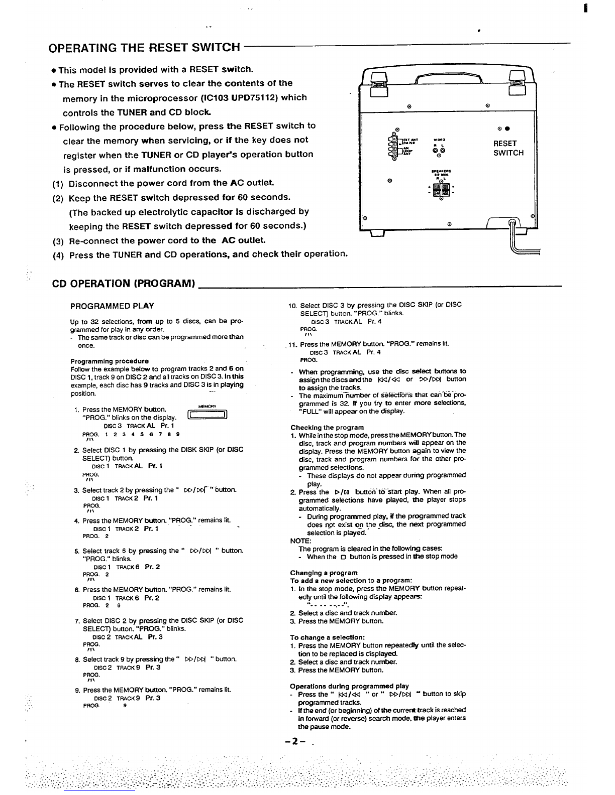
OPERATING THE RESET SWITCH
●This model is provided with aRESET switch.
●The RESET switch serves to clear the contents of the
memory in the microprocessor (IC103 UPD75112) which
controls the TUNER and CD block.
●Following the procedure below, press the RESET switch to
clear the memory when servicing, or if the key does not
register when the TUNER or CD playe~s operation button
is pressed, or if malfunction occurs.
(1)
(2)
(3)
(4)
Disconnect the power cord from the AC outlet.
Keep the RESET switch depressed for 60 seconds.
(The backed up electrolytic capacitor is discharged by
keeping the RESET switch depressed for 60 seconds.)
Re-connect the power cord to the AC outlet.
Press the TUNER and CD operations, and check their operation.
RESET
SWITCH
—111—
CD OPERATION (PROGRAM)
....
..
PROGRAMMED PLAY
Up to 32 selections, from up to 5discs, can be pro-
grammed for play in any order.
The same track or disc can be programmed more then
once.
Programming procedure
Follow the example below to program tracks 2and 6on
DISC 1, track 9on DISC 2and all tracks on DISC 3. in thii
example, each disc has 9tracks and DISC 3is in playing
position. -..
1. Press the MEMORY button.
“’PROG.” blinks on the display. *
Disc 3TRAcKAL i%. 1
P~~1234S 6789
2. Select DISC 1by pressingthe DISK SKiP (or DISC
SELECT button.
OISC1TMCK AL Pr. 1
PROG.
/1!
3. Select track 2by pressing the” DD/ti ““button.
OISC1TRACK 2Pr. 1
PROG.
/!!
4. Press the MEMORY button. “’PROG.” remains fit.
OISC1TPACK2pr. i
PROG. 2
5. Select track 6by pressing the “ DO/M2 0’ button.
“PROG.” blinks.
OISC1TRACK 6Pr. 2
PROO. 2
11!
6. Press the MEMORY button. “PROG.” remains lit.
DISC1TRACK6Pr. 2
PROG. 2 6
7. Select DISC 2by pressing the DISC SKIP (or DISC
SELECT) button. “PROG.” blinks.
DISC2TPACK AL Pr. 3
P~~.
6. Select track 9by pressing the” CO/cci “’button.
DISC2TRACK 9pr. 3
PROG.
Ilt
9. Press the MEMORY button. “PROG.” remains lit.
DISC2TRACK9Pr. 3
PROG. 9
10. Select DISC 3by pressing the DISC SKIP (or DISC
SELECT) button. “’PROG.” blinks.
OISC3TRACKAL P;. 4
PROG.
18$
.11. Press the MEMOFtY button. ““PROG.” remains lit.
Disc 3TPACKAL Pr. 4
PRCG.
When programming, use the disc aefect buttons to
assign the discs end the K</~ or >>/CCi button
to assign the tracks.
The maximurn%umber of selections that ceh-t%-pr~
grammed is 32. ff you try to enter more selections,
“’FULL” will appear on the display.
Checking the program
1. While inthe stop mode, press the MEMORY button. The
disc, track and program numbers wiff appear on the
display. Press the MEMORY button again to view the
disc, track and program numbers for the other pro-
grammed selections.
These displays do not appear during programmed
play.
2Press-the D/oo button” to--at-m Pkw. when all Pro-
grammed selections have played, the player stops
automatically.
During programmed play. if the programmed track
does not exist ofl \he -d=, the next programmed
selection is played.
NOTf3
The program is cleared in the following cases
When the ❑button is pressed in the stop mode
Changing aprogram
To add anew aelectlon to aprogram:
1. In the stop mode. press the MEMORY butron repeat-
edly until the following display appears
“’-- . . . ....”.
2. Select adisc and track number.
3. Press the MEMORY button.
To change aselection:
1. Press the MEMORY button repeatedly until the selec-
tion to be replaced is displayed.
2. Select adisc and track number.
3. Prass the MEMORY bulton.
Operation during programmed play
-Press the “ Mlad “ or” WIDC4 -button to S~P
programmed tracks.
If the end (or beginning) of the currera srack is reached
in forward (or reverse) search mode, @w player enters
the pause mode.
-2- .


 User manual")


 User manual")