Sanyo VA-EXH User manual

External Storage Unit
About this manual
Before installing and using this unit, please read
this manual carefully. Be sure to keep it handy for
later reference.
Über diese Anleitung
Lesen Sie bitte diese Bedienungsanleitung vor der
Installation und der Verwendung des Gerätes sorgfältig
durch. Bewahren Sie die Anleitung zum späteren
Nachschlagen auf.
À propos de ce manuel
Avant d’installer et d’utiliser cet appareil, veuillez lire ce
manuel attentivement. Assurez-vous de le garder à
portée de la main pour référence ultérieure.
Acerca de este manual
Antes de instalar y usar este aparato, lea detenidamente
este manual. Asegúrese de guardarlo a mano para
futuras referencias.
Nota su questo manuale
Leggere attentamente questo manuale prima di passare
all’installazione ed all’uso di questo apparecchio.
Conservare il manuale in un posto sicuro per riferimenti
futuri.
Instruction manual
English GB
Bedienungsanleitung
Deutsch D
Manuel D’instructions
F
Manual de Instrucciones
E
Manuale di Istruzioni
Italiano I
VA-EXH
e00_l8hcb_xe_7.book Page 1 Thursday, March 10, 2005 3:23 PM

English 1
INTRODUCTION
Main features
Connect up to four 3.5-inch S-ATA hard disks
Accessories
Check that you have all the parts shown below.
Power cord
External storage unit cable
(x4)
Core clamp (round)
(x8)
For use with the external
storage unit cables
Core clamp (square)
(x1)
For use with the external
storage unit cables
Cord tie
(x9)
Cable securing
bracket (x2)
Screw (x8)
Hard disk setscrew (x16)
Instruction Manual
Contents
1 BEFORE USE ................................................ 3
Notes on handling the internal hard disk ........ 3
Notes on installation locations ........................ 3
The hard disk and cooling fan are consumable
components.
................................................... 3
Important recordings ...................................... 3
Protection of the hard disk ............................. 3
Supported hard disks ..................................... 3
2 NAMES AND FUNCTIONS OF PARTS ........ 4
Front panel ..................................................... 4
Rear panel ...................................................... 4
1 HARD DISK INSTALLATION AND
CONNNECTION TO DVR .............................. 5
Installing the hard disk ................................... 5
Connecting the DVR ...................................... 8
Turning on the power ..................................... 9
2 INITIALIZING THE HARD DISK .................. 10
Initializing the hard disk ................................ 10
APPENDIX.................................................... 12
Specifications ................................................ 12
Dimensions ................................................... 12
Copyright
zThis manual is copyrighted by Sanyo Electric Co., Ltd.
zBrand and product names used in this manual are the
trademarks or registered trademarks of their respective
companies.
Except for personal use, copyright law prohibits the use of
recorded copyrighted images without the permission of the
copyright holder.
INTRODUCTION
OPERATION
OTHER
e00_l8hcb_xe_7.book Page 1 Thursday, March 10, 2005 3:23 PM

2English
PRECAUTION
Location
For safe operation and satisfactory performance of your
unit, keep the following in mind when selecting a place for
its installation:
Shield it from direct sunlight and keep it away from sources
of intense heat.
Avoid dusty or humid places.
Avoid places with insufficient ventilation for proper heat
dissipation. Do not block the ventilation holes at the top and
bottom of the unit. Do not place the unit on a carpet
because this will block the ventilation holes.
Install the unit in a horizontal position only.
Avoid locations subject to strong vibrations.
Avoid moving the unit between cold and hot locations.
Do not place the unit directly on top of a monitor TV, as this
may cause playback or recording problems.
Avoiding Electrical Shock and Fire
Do not handle the power cord with wet hands.
Do not pull on the power cord when disconnecting it from
an AC wall outlet. Grasp it by the plug.
If any liquid is spilled on the unit, unplug the power cord
immediately and have the unit inspected at a factory-
authorised service centre.
Do not place anything directly on top of this unit.
SERVICE
This unit is a precision instruments and if treated with care,
will provide years of satisfactory performance. However, in
the event of a problem, the owner is advised not to attempt
to make repairs or open the cabinet. Servicing should
always be referred to your dealer or Sanyo Authorized
Service Centre.
For EU Users
Your SANYO product is designed and
manufactured with high quality materials
and components which can be recycled
and reused.
This symbol means that electrical and
electronic equipment, at their end-of-life,
should be disposed of separately from
your household waste.
Please dispose of this equipment at your local community
waste collection/recycling centre.
In the European Union there are separate collection
systems for used electrical and electronic products.
Please help us to conserve the environment we live in!
WARNING: TO REDUCE THE RISK OF FIRE OR
ELECTRIC SHOCK, DO NOT EXPOSE THIS
APPLIANCE TO RAIN OR OTHER MOISTURE.
To avoid electrical shock, do not open the cabinet.
Refer servicing to qualified personnel only.
If the power supply cord (AC power cord) of this appliance
is damaged, it must be replaced. Return to a SANYO
Authorised Service Centre for replacement of the cord.
CAUTION
Danger of explosion if battery is incorrectly replaced.
Replace only with the same or equivalent type
recommended by the manufacturer.
Discard used batteries according to the manufacture’s
instructions.
e03_l8hcb_xe_7.fm Page 2 Monday, March 28, 2005 2:10 PM

English 3
1BEFORE USE
Notes on handling the internal hard disk
Be sure to observe the following points carefully when
operating, setting-up, or servicing the external storage unit.
Do not subject the external storage unit to
sudden impact or vibration.
If the external storage unit is subjected to sudden impact or
vibration, it may damage the hard disk or cause corruption of
the data stored within it.
zDo not move the external storage unit while the power is
turned on. Always ensure that the power is turned off
before removing the external storage unit from or placing it
in a rack.
zWhen transporting the external storage unit, pack it
securely using the specified materials. In addition, choose
a method of transportation that minimizes vibration.
zWhen placing the external storage unit on the floor or
another similar surface, attach the specified pads to its
base and place it down gently.
Do not move the external storage unit for 30
seconds after turning off the power.
After the power is turned off, the disk inside the hard disk
continues to spin for a brief period due to inertia and the
heads are in an unstable condition.
During this period, the external storage unit is even more
susceptible to damage from sudden impact and vibration than
when it is turned on. Make sure that the external storage unit
is not subjected to even gentle vibration for at least 30
seconds after turning off the power.
Do not operate the external storage unit when
condensation has formed on it.
If the external storage unit is operated in this type of condition,
there is a possibility that it may become permanently
damaged.
If the temperature around the external storage unit changes
suddenly, wait for it to stabilize before operating the external
storage unit.
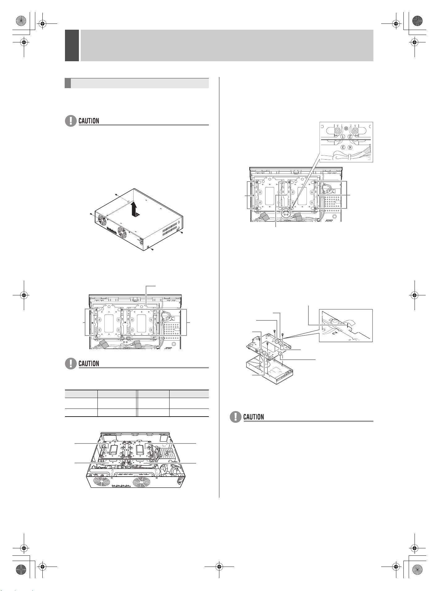
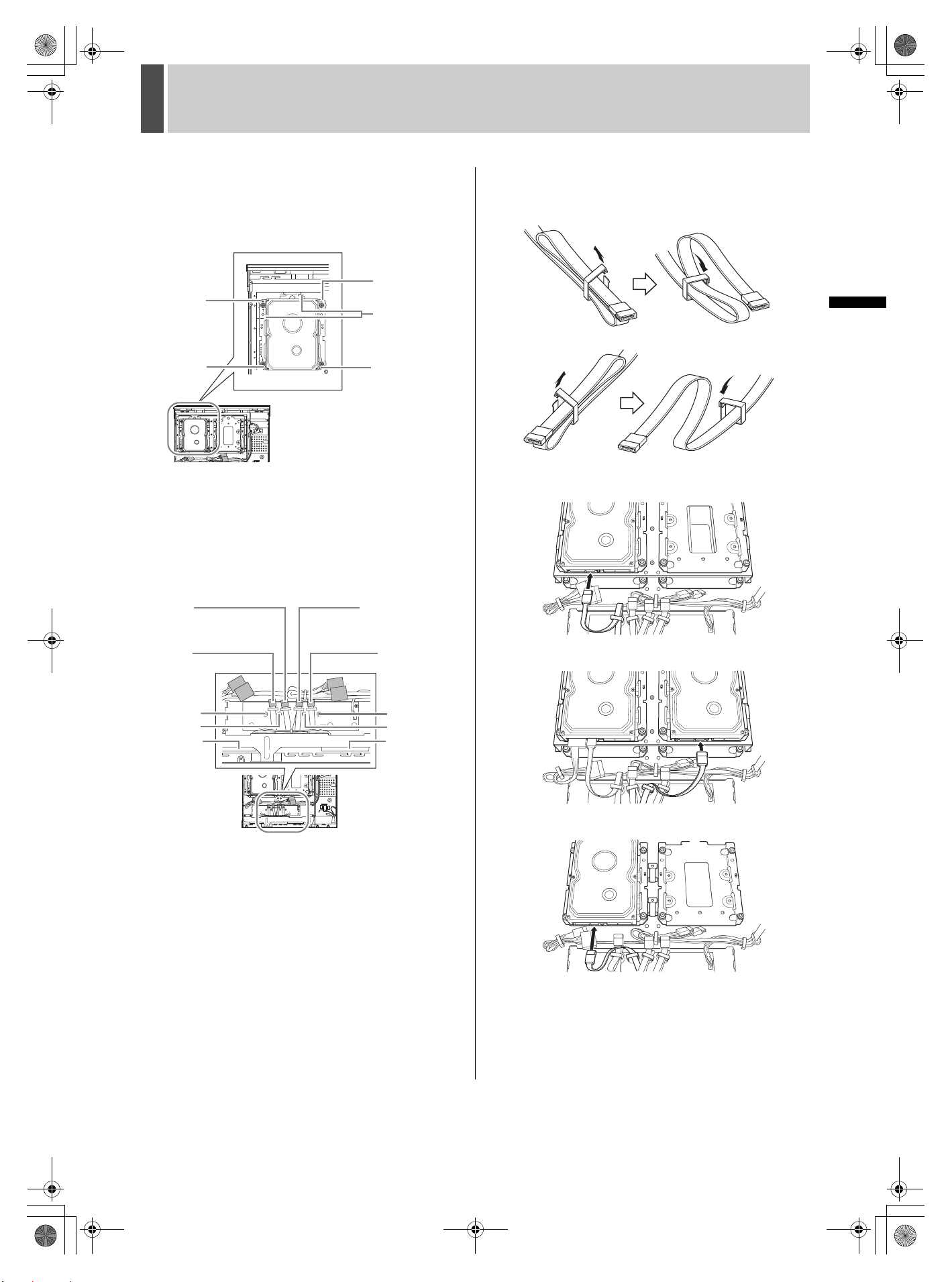
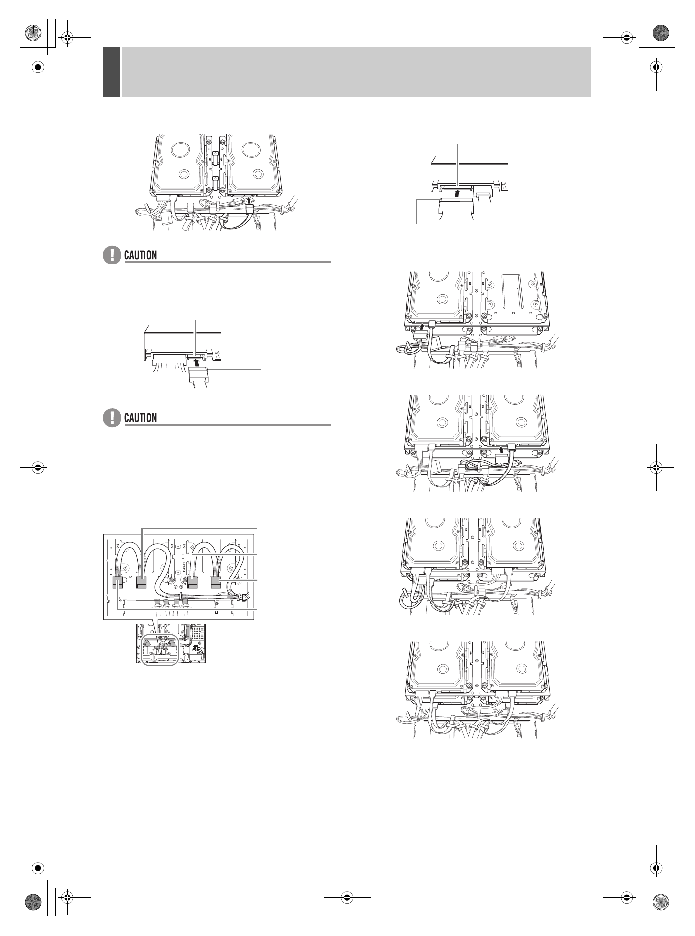
Notes on replacing the hard disk
Be sure to follow the correct procedure when replacing the
hard disk.
zHard disks that have been removed from their packing may
not operate correctly if they are subjected to sudden impact
or vibration. It is recommended that you place the hard disk
on a soft, level surface with the printed circuit board facing
upward after it has been unpacked.
zTake care to avoid subjecting the hard disk to sudden
impact or vibration when removing and tightening screws
as part of the hard disk replacement procedure.
Tighten all screws securely to ensure that they do not
loosen.
zThe hard disk is sensitive to static electricity; accordingly,
you should take the appropriate precautions to prevent the
buildup of static charges.
Handling a detached hard disk unit
If transporting or storing the hard disk unit in a detached
condition, be sure to first of all pack it using the specified
materials.
In addition, choose a method of transportation that minimizes
vibration.
Notes on installation locations
Avoid subjecting the hard disk to sudden impact or vibration.
In addition, avoid using it in dusty locations or near magnetic
objects. The following precautions should be observed in
order to prevent the loss of recorded data:
zDo not subject the external storage unit to sudden impact.
zDo not use the external storage unit on a vibrating or
unstable surface.
zDo not disconnect the power plug from the wall outlet
during recording or playback.
zDo not use the external storage unit in areas with extreme
temperature changes (i.e., 10ºC or more per hour).
zCondensation may occur if the external storage unit is
moved to an area with a significantly different temperature
or high humidity. If the external storage unit is used with
condensation inside, operating problems may occur.
zDo not install the external storage unit inside motor
vehicles, trains, or other areas with constant vibration.
zThe external storage unit has ventilation holes on its left,
rear, and bottom panels. Ensure that these holes are not
blocked after installation.
zDo not use the external storage unit in a bookshelf, box, or
any other area with poor ventilation.
zThis external storage unit is designed for use in a
horizontal orientation, and vertical setup may result in
malfunction.
zWhen installing the unit on a rack, ensure that a gap of at
least 5 cm at the sides and 1 cm at the top and bottom is
provided.
The hard disk and cooling fan are
consumable components.
If used in an ambient temperature of 25ºC, the hard disk
should generally be replaced after two years, and the cooling
fan after three years. These figures are intended as a general
guideline only and should not be taken as a guarantee of
component performance.
The FAN error indicator flashes if a problem occurs with the
fan.
Important recordings
Always perform test recording in advance to confirm whether
the playback of the external storage unit is normal.
Note that Sanyo accepts no responsibility for losses occurring
as a result of recording or playback problems caused by
malfunction of this external storage unit or any connected
devices.
As a precaution against malfunction or accidents, it is
advisable to periodically back up important recordings or to
perform mirroring.
Protection of the hard disk
The hard disk is checked automatically when the power is
turned on. If an abnormality is detected, the ERROR indicator
of the digital video recorder begins to flash. To initialize the
hard disk or to save images stored on it, contact the dealer
from whom this external storage unit was purchased.
Supported hard disks
Use hard disks recommended by Sanyo. Please contact the
dealer for details.
e00_l8hcb_xe_7.book Page 3 Thursday, March 10, 2005 3:23 PM

4English
INTRODUCTION OTHEROPERATION
2NAMES AND FUNCTIONS OF PARTS
Front panel
1. POWER indicator
Lights up when the power is on.
2. Fan abnormality indicator
Flashes if the fan begins to malfunction.
Rear panel
1. Fan
2. External storage unit terminal
Connection point for the external storage unit cable when
connecting the external storage unit to the digital video
recorder.
3. AC power socket
Insert the supplied power cord securely into this socket.
4. Cord tie
Secure the power card to the holder using the cord tie
(accessory) as shown in the illustration.
POWER FAN
12
DIGITAL VIDEO RECORDER
AC IN~
2
1
3
4
e00_l8hcb_xe_7.book Page 4 Thursday, March 10, 2005 3:23 PM

English 5
1
HARD DISK INSTALLATION AND CONNNECTION TO DVR
Use the following procedures to install the hard disk in the
external storage unit.
zThe external storage unit must be off before commencing
the following procedures.
zUse only S-ATA hard disks from Sanyo. Operation by other
hard disks is not guaranteed. Contact the dealer for details.
1Remove the four screws (two on each
side) securing the cover, and remove
the cover.
2Remove the hard disk bay.
Remove the four screws (two on each side), and remove the
hard disk bay on top of the installation block.
zThe position of the hard disk differs according to the
number of units being installed. Numbers are marked near
the hard disk bay. Follow the chart below.
zThe positions are shown below.
zTo install the hard disk in positions 3and 4, remove the
installation block, and then the hard disk bay.
[Removing the installation block]
(1) Remove the nine screws.
(2) Slide the center of the front part toward the back panel
and remove the hard disk installation block.
For instructions on how to attach the installation block, see
[Attaching the installation block]. (JP.8)
3Attach the hard disk bay removed in
step 2 to the hard disk.
Secure the screws in the order (1-4) marked on the hard disk
bay.
* Tightening torque: 0.5 N•m - 0.6 N•m (5 - 6 kgf•cm)
Do not use a torque screwdriver.
zIncluded with this unit are short screws for securing the
hard disk and long screws for securing the external storage
unit cable bracket.
Use the short screws for securing the hard disk.
Installing the hard disk
No. of units Position No. of units Position
1131, 2, 3
21, 24 1, 2, 3, 4
Screws
Hard disk bay
Screws
Front panel side
1
3
2
4
Screws
Screws
Position
markings
(1- 4)
Screws
Ensure the fittings exceed 10 mm in height.
If not, repair them.
Fitting
“1”
“3”
“2”
“4”
Bring the hard disk
connector to the side
with “CN.”
e00_l8hcb_xe_7.book Page 5 Thursday, March 10, 2005 3:23 PM

6English
HARD DISK INSTALLATION AND CONNNECTION TO DVR1
INTRODUCTION OTHEROPERATION
4Attach the hard disk bay with the hard
disk attached to it in step 3 to the
external storage unit.
Secure the screws in the order (1-4) marked on the hard disk
bay.
* Tightening torque: 0.6 N•m - 0.7 N•m (6 - 7 kgf•cm)
5Connect the cable to the hard disk.
(1) Select the cable with the same number as the hard disk
bay with the hard disk attached to it, and remove the
securing clamp.
* The cable number is printed near each cable.
* Use a screwdriver to remove the clamps.
(2) To prevent the cables coming in contact with the fan,
secure them with the clamps. The securing procedure
differs according to the cable number.
[Arranging the cables]
Connecting the cable to the first hard disk (1)
Connecting the cable to the second hard disk (2)
Connecting the cable to the third hard disk (3)
“2”
“1”
“4”
“3”
Match the
markings.
“2”
“4”
“3”
“1”
Hard disk
connector for
the 4th hard
disk
Hard disk
connector for the
2nd hard disk
Hard disk
connector for
the 1st hard
disk
Hard disk
connector for the
3rd hard disk
Fan Fan
1and 4
2and 3
4
2 1
3
4
2 1
3
4 3
e00_l8hcb_xe_7.book Page 6 Thursday, March 10, 2005 3:23 PM

HARD DISK INSTALLATION AND CONNNECTION TO DVR1
English 7
Connecting the cable to the fourth hard disk (4)
zArrange the cables so that they do not come in contact with
the fan.
(3) Connect the cable to the S-ATA terminal on the hard disk.
zConfirm the position of the rib before inserting the
connector.
6Connect the power cord.
(1) Select the power cord with the same number as the hard
disk in step 5, and remove the securing clamp with a
screwdriver.
* See the following diagram for cord numbers.
(2) To prevent the cords coming in contact with the fan,
secure them at two points with the clamps.
(3) Connect the cord to the hard disk power connector.
[Arranging the cables]
The first hard disk is installed in position 1.
The second hard disk is installed in position 2.
The third hard disk is installed in position 3.
The fourth hard disk is installed in position 4.
4 3
S-ATA terminal
Rib
3: Cord for the
third hard disk
2: Cord for the
second hard disk
4: Cord for the
fourth hard disk
1: Cord for the
first hard disk
Power connector
Rib
4
2 1
3
4
2 1
3
4 3
2 1
4 3
2 1
e00_l8hcb_xe_7.book Page 7 Thursday, March 10, 2005 3:23 PM

8English
HARD DISK INSTALLATION AND CONNNECTION TO DVR1
INTRODUCTION OTHEROPERATION
zIf expanding the number of hard disks to three or more,
install the first one to 3and the second one to 4,
reattach the installation block that was removed in step 2,
and then install the last two hard disks to 1and 2.
[Attaching the installation block]
Insert projection A into hole B by sliding the center of the front
part. Align the positioning points on both sides two at a time
and secure the nine points with screws.
* Insert projection A properly or else the hard disk installation
block cannot be attached correctly.
* Tightening torque: 0.6 N•m - 0.7 N•m (6 - 7 kgf•cm)
7After installing the hard disk, follow the
procedure shown in step 1 in reverse
order to close the cover.
Use the following procedures to connect the DVR to the
external storage unit.
1Use the four external storage unit
cables included with this product to
connect the external storage unit to the
DVR.
zEven if there are only one to three hard disks, connect all
four external storage unit cables.
zMake sure to connect correspondingly numbered terminals
on the external storage unit and DVR.
2Use the supplied bracket to secure the
external storage unit cables.
zUse another supplied bracket to secure the cables at the
DVR end as well.
Positioning points
B
Positioning points
A
Connecting the DVR
1234
External
storage unit
connection
terminals
External
storage
unit
DVR
Rib
External
storage unit
cable
Rib
Bracket
(supplied)
Screws
(supplied)
e00_l8hcb_xe_7.book Page 8 Thursday, March 10, 2005 3:23 PM

HARD DISK INSTALLATION AND CONNNECTION TO DVR1
English 9
3Attach a supplied core clamp to the
external storage unit cable.
: Core clamp (round)
Attach near each connector.
: Cord tie
Secure the core clamp with a cord tie so that it does
not slip.
: Core clamp (square)
Attach around bundle of external storage unit cables
at the mid point between the external storage unit and
the DVR.
zAttach the core clamps (round) to the cables at the DVR
end in the same way and secure with cord ties.
1When you have finished making all the
connections on the DVR and external
storage unit, make sure the voltage is
120 - 240V AC and then insert the power
plug of the external storage unit into the
wall outlet.
2Turn on the DVR.
zAs the external storage unit takes time to recognize the
hard disks, turn on the external storage unit before turning
on the DVR.
Turning on the power
120 - 240V AC
(50/60 Hz)
e00_l8hcb_xe_7.book Page 9 Tuesday, March 22, 2005 4:51 PM

10 English
INTRODUCTION OTHEROPERATION
2INITIALIZING THE HARD DISK
Use the setting screen on the digital video recorder to initialize
the hard disk.
The capacity of the built-in hard disks is displayed as DISK 1
and DISK 2. The hard disk capacity for the external storage
unit is displayed as EX-DISK 1 to 4.
zInitialization must always be performed after expanding the
hard disk.
zAll important recordings should be copied to CompactFlash
cards or other storage media before expanding the hard
disk.
1Turn on the DVR to display the <HDD
SET> screen.
To initialize a recently expanded hard disk, select “NEW DISK
INITIALIZE”.
To initialize all connected hard disks, select “ALL DISK
INITIALIZE”.
zMirroring commences if “MIRRORING” is set “ON.”
2Then turn the shuttle dial clockwise.
The <WARNING> screen is displayed. “NO” is flashing.
3Turn the jog dial to select “YES” and
then turn the shuttle dial clockwise.
The “HDD INITIALIZING !” screen is displayed and the hard
disk is initialized.
When initialization is complete, the live image is displayed.
1Press the [MENU] button.
The MENU indicator lights up and the <MAIN MENU> is
displayed.
2Turn the jog dial to select “3.GENERAL
SET” and then turn the shuttle dial
clockwise.
The <GENERAL SET> screen is displayed.
3Turn the jog dial to select “5.HDD SET”
and then turn the shuttle dial clockwise.
The <HDD SET> screen is displayed.
To initialize a recently expanded hard disk, select “NEW DISK
INITIALIZE”.
To initialize all connected hard disks, select “ALL DISK
INITIALIZE”.
Initializing the hard disk
Initializing the hard disk at power on
<HDD SET>
DISK 1 : 160GB NEW DISK 2 : 160GB NEW
EX-DISK 1 : 160GB NEW EX-DISK 2 : 160GB NEW
EX-DISK 3 : 160GB NEW EX-DISK 4 : 160GB NEW
NEW DISK INITIALIZE ->
PLEASE INITIALIZE THE NEW DISK
MIRRORING : OFF
PLAYBACK DRIVE : ***
CAUTION : RECORDING SPEED WILL BE
LIMITED BY MIRRORING !
ALL DISK INITIALIZE ->
“NEW” is displayed to
the right of the hard
disk capacity for new
hard disks.
<WARNING>
THIS CHANGE WILL INITIALIZE THE DISK.
ALL RECORDING WILL BE ERASED.
ARE YOU SURE ?
NO
CHANGE:JOG SET:SHUTTLE
Initializing the hard disk in use
MENU
<HDD SET>
DISK 1 : 160GB DISK 2 : 160GB
EX-DISK 1 : 160GB EX-DISK 2 : 160GB
EX-DISK 3 : 160GB EX-DISK 4 : 160GB
NEW DISK INITIALIZE ->
PLEASE INITIALIZE THE NEW DISK
MIRRORING : OFF
PLAYBACK DRIVE : ***
CAUTION : RECORDING SPEED WILL BE
LIMITED BY MIRRORING !
ALL DISK INITIALIZE ->
“NEW” is displayed to
the right of the hard
disk capacity for new
hard disks.
e00_l8hcb_xe_7.book Page 10 Thursday, March 10, 2005 3:23 PM

INITIALIZING THE HARD DISK2
English 11
4Then turn the shuttle dial clockwise.
The <WARNING> screen is displayed. “NO” is flashing.
5Turn the jog dial to select “YES” and
then turn the shuttle dial clockwise.
The “HDD INITIALIZING !” screen is displayed and the hard
disk is initialized.
When initialization is completed, the display returns to the
<HDD SET> screen.
6Press the [EXIT/OSD] button.
The setting is completed and the display returns to the normal
screen.
zMirroring commences if “MIRRORING” is set “ON” in step
3. Mirroring is performed in the following combinations:
• EX-DISK 1 and EX-DISK 2
• EX-DISK 3 and EX-DISK 4
<WARNING>
THIS CHANGE WILL INITIALIZE THE DISK.
ALL RECORDING WILL BE ERASED.
ARE YOU SURE ?
NO
CHANGE:JOG SET:SHUTTLE
HDD INITIALIZING !
EXIT/OSD
EXIT/OSD
e00_l8hcb_xe_7.book Page 11 Thursday, March 10, 2005 3:23 PM

12 English
INTRODUCTION OTHEROPERATION
APPENDIX
Note that product appearance and specifications are subject to change without prior notice.
Units: mm
Specifications
Product name External storage unit
Product number VA-EXH
EMC standard CE
Safety standard CE
Mirroring Available
Hard disk bay 3.5-inch (x4)
Terminal 7-pin external storage unit connection terminal (x4)
Power supply voltage 120 - 240V AC, 50/60 Hz
Current consumption 680 mA
Allowable operating temperature 5 - 40ºC
Allowable operating humidity 10 - 80%
Dimensions 420 (W) x 86 (H) x 344 (D) mm (Not including protruding areas or rubber pads)
Weight 6 kg without hard disk, 6.6 kg with a HDD, 7.2 kg with 2 HDDs
Accessories
Power cord (x1), External storage unit cable (x4), Cable securing bracket (x2),
Bracket setscrew (x8), Cord tie (x9), Round core clamp (x8), Square core clamp (x1),
Hard disk setscrew (x16), Instruction Manual (x1)
Dimensions
96
420 344
10
e06_l8hcb_xe_7.fm Page 12 Tuesday, March 22, 2005 7:54 PM

e00_l8hcb_xe_7.book Page 13 Thursday, March 10, 2005 3:23 PM

Externes Speichermedium
VA-EXH
d00_l8hcb_xe_7.book Page 1 Tuesday, March 22, 2005 2:23 PM

Deutsch 1
EINFÜHRUNG
Die wichtigsten Funktionen im Überblick
Schließen Sie bis zu vier 3,5-Zoll S-ATA-
Festplatten an
Zubehör
Vergewissern Sie sich, dass Sie alle nachfolgend
aufgeführten Teile verfügbar haben.
Netzkabel
Kabel des externen
Speichermediums
(x4)
Ferritkern (rund)
(x8)
Zur Verwendung mit den
Kabeln des externen
Speichermediums
Ferritkern (quadratisch)
(x1)
Zur Verwendung mit den
Kabeln des externen
Speichermediums
Kabelbinder
(x9)
Kabelbefestigungs-
halterung (x2)
Schraube (x8)
Festplatten-
Stellschraube (x16)
Bedienungsanleitung
Inhalt
1 VOR DEM GEBRAUCH.................................. 3
Hinweise zum Umgang mit der internen
Festplatte ........................................................ 3
Hinweise zum Installationsort.......................... 3
Die Festplatte und der Kühllüfter sind
Verschleißteile................................................. 3
Wichtige Aufzeichnungen................................ 3
Festplattenschutz ............................................ 3
Unterstützte Festplatten .................................. 3
2 BEZEICHNUNGEN UND FUNKTIONEN
DER TEILE ..................................................... 4
Gerätevorderseite ........................................... 4
Geräterückseite............................................... 4
1 INSTALLATION DER FESTPLATTE UND
ANSCHLUSS AN DEN DVR .......................... 5
Installieren der Festplatte................................ 5
Anschließen des DVR ..................................... 8
Einschalten des Geräts ................................... 9
2 INITIALISIEREN DER FESTPLATTE .......... 10
Initialisieren der Festplatte ............................ 10
ANHANG ...................................................... 12
Technische Daten ......................................... 12
Abmessungen ............................................... 12
Urheberrecht
zDas Handbuch unterliegt dem Urheberrecht der Sanyo
Electric Co., Ltd.
zBei allen in diesem Handbuch erwähnten Marken- und
Produktnamen handelt es sich um die
Markenbezeichnungen und registrierten Warenzeichen
ihrer jeweiligen Eigentumsgesellschaften.
Die Urheberrechtsvorschriften sehen vor, dass
aufgenommene und unter die Urhebergesetze fallende Bilder
ohne ausdrückliche Genehmigung des
Urheberrechtsinhabers nur für den persönlichen Gebrauch
verwendet werden dürfen.
EINFÜHRUNG
BEDIENUNG
SONSTIGES
d00_l8hcb_xe_7.book Page 1 Tuesday, March 22, 2005 2:23 PM

2Deutsch
VORSICHTSMAßNAHMEN
Aufstellungsort
Für einen sicheren Betrieb und eine gute Leistung des Geräts
müssen Sie bei der Wahl des Aufstellungsortes die folgenden
Punkte beachten.
Schützen Sie das Gerät vor direkter Sonneneinstrahlung und
halten Sie ihn von Wärmequellen fern.
Vermeiden Sie einen staubigen oder feuchten Aufstellungsort.
Vermeiden Sie einen schlecht belüfteten Aufstellungsort, an
dem die Wärme nicht abgeführt werden kann. Die
Belüftungsöffnungen an der Ober- und Unterseite des Geräts
dürfen nicht abgedeckt werden. Nicht auf einem Teppich
aufstellen, weil die Belüftungsöffnungen blockiert werden.
Das Gerät darf nur horizontal aufgestellt werden.
Aufstellungsorte, an denen starke Vibrationen auftreten, sind
zu vermeiden.
Das Gerät darf keinen hohen Temperaturschwankungen
ausgesetzt werden.
Das Gerät darf nicht direkt auf einem Fernsehgerät aufgestellt
werden, weil Störungen bei der Wiedergabe und der
Aufnahme auftreten können.
Vermeidung von elektrischen Schlägen
und Brandausbrüchen
Berühren Sie das Netzkabel nicht mit nassen Händen.
Ziehen Sie beim Lösen des Steckers aus der Steckdose nicht
am Kabel. Halten Sie immer den Stecker fest.
Falls auf dem Gerät Flüssigkeiten verschüttet worden sind,
müssen Sie das Netzkabel sofort aus der Steckdose ziehen.
Lassen Sie das Gerät von einem autorisierten Kundendienst
überprüfen.
Stellen Sie keine Gegenstände direkt auf das Gerät.
KUNDENDIENST
Dies ist ein Präzisionsgerät. Bei sorgfältiger Behandlung
können Sie einen langjährigen problemfreien Betrieb erwarten.
Sollten dennoch Störungen auftreten, so sollten Sie davon
absehen, das Gerät selbst zu reparieren oder das Gehäuse zu
öffnen. Wenden Sie sich für Reparaturen stets an Ihren
Händler oder an einen autorisierten Sanyo-Kundendienst.
Für Verbraucher in der Europäischen
Union
Ihr SANYO Produkt wurde entworfen und
hergestellt mit qualitativ hochwertigen
Materialien und Komponenten, die recycelt
und wiederverwendet werden können.
Dieses Symbol bedeutet, daß elektrische
und elektronische Geräte am Ende ihrer
Nutzungsdauer von Hausmüll getrennt
entsorgt werden sollen.
Bitte entsorgen Sie dieses Gerät bei Ihrer
örtlichen kommunalen Sammelstelle oder
im Recycling Centre.
In der Europäischen Union gibt es unterschiedliche
Sammelsysteme für Elektrik- und Elektronikgeräte.
Helfen Sie uns bitte, die Umwelt zu erhalten, in der wir leben!
WARNUNG: UM DIE GEFAHR EINES
FEUERAUSBRUCHS ODER EINES ELEKTRISCHEN
SCHLAGES ZU VERRINGERN, DARF DIESES GERÄT
KEINEM REGEN ODER HOHER LUFTFEUCHTIGKEIT
AUSGESETZT WERDEN.
Zur Vermeidung eines elektrischen Schlages darf das
Gehäuse nicht geöffnet werden.
Reparaturen dürfen nur von einem qualifizierten Fachmann
ausgeführt werden.
Ein beschädigtes Netzkabel muss sofort ersetzt werden.
Wenden Sie sich dazu an einen autorisierte SANYO-
Kundendienst.
VORSICHT
Bei fehlerhaftem Austauschen der Batterie besteht
Explosionsgefahr.
Die Batterie darf nur gegen eine gleichwertige, bzw. eine
Batterie des gleichen, vom Hersteller empfohlenen Typs
ersetzt werden.
Alte Batterien müssen nach Anweisung des Herstellers
entsorgt werden.
d00_l8hcb_xe_7.book Page 2 Tuesday, March 22, 2005 2:23 PM

Deutsch 3
1VOR DEM GEBRAUCH
Hinweise zum Umgang mit der internen
Festplatte
Beachten Sie beim Gebrauch, beim Einrichten und bei der Pflege
des externen Speichermediums stets die folgenden Hinweise.
Setzen Sie das externe Speichermedium
keinen Erschütterungen oder Vibrationen aus.
Wenn das externe Speichermedium Erschütterungen oder
Vibrationen ausgesetzt wird, kann die Festplatte beschädigt
werden, oder die darauf gespeicherten Daten werden unbrauchbar.
z
Bewegen Sie das externe Speichermedium nicht, solange
es eingeschaltet ist. Überzeugen Sie sich vor dem Ein- oder
Ausbau des externen Speichermediums in/aus ein(em)
Rack stets davon, dass das Gerät ausgeschaltet ist.
zTransportieren Sie das externe Speichermedium nur gut
geschützt und unter Verwendung der dafür bestimmten
Verpackungsmaterialien. Außerdem müssen Sie auf eine
vibrationsfreie oder -arme Transportart achten.
zWenn Sie das externe Speichermedium auf dem Boden
oder einer ähnlichen Fläche aufstellen, bringen Sie die
hierfür bestimmten Polster an der Unterseite an und stellen
Sie das Gerät vorsichtig ab.
Warten Sie nach dem Abschalten immer erst
30 Sekunden ab, bevor Sie das externe
Speichermedium bewegen.
Auch nach dem Abschalten des Geräts laufen die eingebauten
Festplattenscheiben aufgrund ihrer Eigenträgheit noch für
kurze Zeit nach, wobei der Schreib-/Lesekopf instabil ist.
Innerhalb dieser kurzen Zeit ist das externe Speichermedium
daher noch anfälliger für Beschädigung durch Vibrationen und
Erschütterungen als im eingeschalteten Zustand. Achten Sie
daher stets darauf, dass Sie das externe Speichermedium für
mindestens 30 Sekunden nach dem Ausschalten keinerlei
Vibrationen aussetzen.
Schalten Sie das externe Speichermedium
niemals ein, wenn sich darauf zuvor ein
Kondenswasserniederschlag gebildet hat.
Wenn das externe Speichermedium unter diesen
Bedingungen betrieben wird, besteht die Gefahr der
dauerhaften Beschädigung des Geräts.
Sollte das externe Speichermedium plötzlichen Veränderungen der
Umgebungstemperatur ausgesetzt gewesen sein, schalten Sie es
erst ein, nachdem sich die Umgebungstemperatur stabilisiert hat.
Austauschen der Festplatte
Beachten Sie beim Austauschen der Festplatte stets die dafür
bestimmte Vorgehensweise.
zEntnommene Festplatten, die Erschütterungen oder
Vibrationen ausgesetzt werden, funktionieren danach unter
Umständen nicht mehr einwandfrei. Deshalb sollten Sie
eine entnommene Festplatte stets auf einer weichen und
ebenen Unterlage absetzen, wobei die aufgedruckte
Schaltplatine nach oben zeigen muss.
zAchten Sie auch beim Lösen und Wiederanziehen der
Befestigungsschrauben während des Festplattenwechsels
darauf, dass die Festplatte keinen Erschütterungen oder
Vibrationen ausgesetzt wird.
Ziehen Sie alle Befestigungsschrauben fest an, damit sich
die Festplatte nicht aus ihrer Halterung lösen kann.
zDie Festplatte reagiert außerdem empfindlich auf
berührungsbedingte elektrostatische Entladungen.
Deshalb sollten Sie stets die erforderlichen Vorkehrungen
zur Vermeidung elektrostatischer Entladungen treffen,
bevor Sie die Festplatte berühren.
Transport entnommener Festplatten
Wenn Sie vorhaben, eine entnommene Festplatte zu
transportieren, müssen Sie diese zuvor stets in dem dafür
bestimmten Transportgehäuse verpacken.
Außerdem müssen Sie auf eine vibrationsfreie oder -arme
Transportart achten.
Hinweise zum Installationsort
Setzen Sie die Festplatten keinen Erschütterungen oder
Vibrationen aus. Das Gerät sollte zudem nicht an staubigen Orten
oder in der Nähe magnetischer Gegenstände benutzt werden.
Bitte beachten Sie stets die folgenden Sicherheitsvorkehrungen,
um den ungewollten Verlust aufgezeichneter Daten zu vermeiden:
zSetzen Sie das externe Speichermedium keinen
Erschütterungen aus.
zBetreiben Sie das externe Speichermedium nicht auf
vibrierenden oder instabilen Abstellflächen.
z
Ziehen Sie während der Aufzeichnung oder Wiedergabe von
Bildern niemals den Netzstecker des Gerätes aus der Steckdose.
zBetreiben Sie das externe Speichermedium nicht in
Räumlichkeiten, die extremen Temperaturschwankungen
(10ºC pro Stunde oder mehr) ausgesetzt sind.
z
Im Inneren des externen Speichermediums kann sich
Kondenswasserniederschlag bilden, wenn das Gerät an einen Ort
mit stark veränderter Umgebungstemperatur oder erhöhter
Luftfeuchtigkeit verbracht wird. Wenn Sie das externe
Speichermedium trotz vorhandenem Kondenswasserniederschlag
betreiben, können schwere Betriebsstörungen die Folge sein.
zMontieren Sie das externe Speichermedium niemals an
Orten mit permanent vorhandenen Vibrationen, z.B. in
Kraftfahrzeugen oder Zügen.
z
Das Gehäuse des externen Speichermediums ist links, oben und
unten mit Belüftungsöffnungen versehen. Diese
Belüftungsöffnungen dürfen nach der Montage nicht verdeckt sein.
z
Betreiben Sie das externe Speichermedium deshalb auch
nicht an einem Aufstellort mit unzureichender Belüftung, z.B.
in einem Bücherregal oder in einem geschlossenen Behälter.
zDas externe Speichermedium muss für den Betrieb
waagerecht aufgestellt werden. Der Betrieb in senkrechter
Lage kann zu Fehlfunktionen führen.
zBeim Einbau des Geräts in ein Rack muss ein Montage-
Mindestabstand von 5 cm an den Seiten und 1 cm auf der
Oberseite und der Unterseite eingehalten werden.
Die Festplatte und der Kühllüfter sind
Verschleißteile
Wird das Gerät durchgehend bei einer Umgebungstemperatur
von 25ºC betrieben, muss die Festplatte in der Regel alle 2
Jahre ausgewechselt werden, der Kühllüfter alle 3 Jahre.
Diese Werte dienen lediglich als allgemeine Richtlinie und
verstehen sich nicht als Garantie für die Leistung der Bauteile.
Sobald am Kühllüfter eine Betriebsstörung vorliegt, beginnt
die FAN-Anzeige zu blinken.
Wichtige Aufzeichnungen
Überprüfen Sie stets mit einer Testaufnahme den ordnungsgemäßen
Aufnahme- und Wiedergabebetrieb des externen Speichermediums,
bevor Sie eine wichtige Aufnahme erstellen.
Beachten Sie bitte, dass Sanyo keinerlei Verantwortung für jegliche
Verluste übernimmt, die ggf. durch Aufnahme- oder
Wiedergabestörungen beim Betrieb des externen Speichermediums
oder der mit ihm verbundenen Anlagen und Geräte entstehen.
Erstellen Sie daher in regelmäßigen Abständen
Sicherheitskopien von Ihren wichtigen Aufnahmen, damit Ihnen
im Fall einer Fehlfunktion oder eines versehentlichen
Handhabungsfehlers keine wichtigen Bilddaten verloren gehen.
Festplattenschutz
Beim Einschalten des Geräts überprüft dieses jeweils
automatisch den Zustand der Festplatte. Wenn eine
Unregelmäßigkeit erkannt wird, beginnt die ERROR-Anzeige
am digitalen Videorekorder zu blinken. Bitte wenden Sie sich an
den Fachhändler, bei dem Sie das externe Speichermedium
erworben haben, wenn Sie eine Festplatte initialisieren oder
darauf vorhandene Bilder vor dem Verlust bewahren möchten.
Unterstützte Festplatten
Verwenden Sie von Sanyo empfohlene Festplatten. Wenden
Sie sich für nähere Informationen an Ihren Fachhändler.
d00_l8hcb_xe_7.book Page 3 Tuesday, March 22, 2005 2:23 PM

4Deutsch
EINFÜHRUNG SONSTIGESBEDIENUNG
2
BEZEICHNUNGEN UND FUNKTIONEN DER TEILE
Gerätevorderseite
1. POWER-Anzeige
Leuchtet in eingeschaltetem Zustand auf.
2. Kühllüfter-Störungsanzeige
Blinkt, wenn eine Störung am Lüfter auftritt.
Geräterückseite
1. Lüfter
2. Anschluss für externes Speichermedium
Anschlussstelle für das Kabel des externen Speichermediums
beim Anschließen des externen Speichermediums an den
digitalen Videorekorder.
3. Netzanschlussbuchse
Stecken Sie das mitgelieferte Netzkabel fest in diese Buchse
ein.
4. Kabelbinder
Fixieren Sie das Netzkabel wie in der Abbildung gezeigt mit
dem (mitgelieferten) Kabelbinder.
POWER FAN
12
DIGITAL VIDEO RECORDER
AC IN~
2
1
3
4
d00_l8hcb_xe_7.book Page 4 Tuesday, March 22, 2005 2:23 PM

Deutsch 5
1
INSTALLATION DER FESTPLATTE UND ANSCHLUSS AN DEN DVR
Gehen Sie folgendermaßen vor, um die Festplatte im
externen Speichermedium zu installieren.
zDas externe Speichermedium muss ausgeschaltet sein,
bevor die folgenden Verfahren begonnen werden.
zVerwenden Sie ausschließlich S-ATA-Festplatten von
Sanyo. Die Funktion mit anderen Festplatten wird nicht
garantiert. Wenden Sie sich für nähere Informationen an
Ihren Fachhändler.
1Entfernen Sie die vier Schrauben (zwei
auf jeder Seite) mit denen die
Abdeckung befestigt ist und nehmen
Sie die Abdeckung ab.
2Entfernen Sie den
Festplatteneinbauschacht.
Entfernen Sie die vier Schrauben (zwei auf jeder Seite) und
entnehmen Sie den Festplatteneinbauschacht oben auf dem
Installationsblock.
zDie Position der Festplatte ist je nach Anzahl der
eingebauten Einheiten verschieden. Die Nummern sind in
der Nähe des Festplatteneinbauschachts vermerkt.
Befolgen Sie die Angaben in der nachstehend
aufgeführten Tabelle.
zUnten sind die Positionen dargestellt.
zZur Installation der Festplatte in den Positionen 3und 4
zunächst den Installationsblock und anschließend den
Festplatteneinbauschacht entfernen.
[Ausbauen des Installationsblocks]
(1) Entfernen Sie die neun Schrauben.
(2)
Schieben Sie die Mitte des vorderen Teils in Richtung der
Geräterückseite und entfernen Sie den Festplatteninstallationsblock.
Anweisungen zum Anbringen des Installationsblocks
finden Sie unter [Einbauen des Installationsblocks]. (JS.8)
3
Befestigen Sie den in Schritt 2 ausgebauten
Festplatteneinbauschacht an der Festplatte.
Befestigen Sie die Schrauben in der Reihenfolge (1-4), wie
auf dem Festplatteneinbauschacht gekennzeichnet.
* Anzugsdrehmoment: 0,5 N•m - 0,6 N•m (5 - 6 kgf•cm)
Keinen Schraubendreher mit Ratsche verwenden.
z
Im Lieferumfang dieses Geräts sind kurze Schrauben für die
Befestigung der Festplatte und lange Schrauben für die Befestigung
der Kabelhalterung des externen Speichermediums enthalten.
Verwenden Sie die kurzen Schrauben für die Befestigung
der Festplatte.
Installieren der Festplatte
Anz. der
Einheiten Position Anz. der
Einheiten Position
1131, 2, 3
21, 24 1, 2, 3, 4
Schrauben Festplatten-
einbauschacht
Schrauben
Gerätevorderseite
1
3
2
4
Positionsmarkierungen
(1- 4)
Schrauben
Schrauben
Schrauben
Überzeugen Sie sich davon, dass die Höhe
der Passstücke mehr als 10 mm beträgt.
Reparieren Sie diese andernfalls.
Passstück
“1”
“3”
“2”
“4”
Bringen Sie den Festplatten-
Steckverbinder auf die mit
“CN” gekennzeichnete Seite.
d00_l8hcb_xe_7.book Page 5 Tuesday, March 22, 2005 2:23 PM
Other manuals for VA-EXH
1
Table of contents
Languages:
Other Sanyo Storage manuals
Popular Storage manuals by other brands

Sony
Sony HD-P Series operating instructions

IBM
IBM SAN768B Installation, service and user guide

Dell
Dell PowerVault MD3260i Series Deployment guide

ulsonix
ulsonix ULX-480-1 user manual

Convex
Convex CSMD2-U440 user guide

Sun Microsystems
Sun Microsystems StorEdge S1 Array Installation and maintenance manual

Pro-Log
Pro-Log 7701 user manual

Sun Microsystems
Sun Microsystems StorEdge L11000 user guide

Seagate
Seagate ST31000340NS - Barracuda 1 TB Hard Drive product manual

Overland Storage
Overland Storage NEO 8000 Remove & Replace Instructions

HP
HP StoreOnce D2D2500 Implementation guide

Raidon
Raidon GT8670-TB3 user manual