TrueNAS ES102 Manual
TrueNAS®ES102 Expansion Shelf
Basic Setup Guide
Version 1.01

Copyright © 2020 iXsystems, Inc. All rights reserved. All trademarks are the property of their respective owners.
Contents
1 Unpacking the Unit ......................................................................... 1
1.2 Become Familiar with the ES102 ............................................................ 2
2 Prerequisites ................................................................................ 3
2.1 Safety ............................................................................................. 3
2.1.1 Static Discharge .................................................................................... 3
2.1.2 Enclosure Size ...................................................................................... 3
2.2 Tools .............................................................................................. 3
2.3 Rack Requirements ............................................................................ 4
3 ES102 Rail Installation Procedures ...................................................... 4
3.1 Enclosure Rails .................................................................................. 4
3.2 Rack Rails ........................................................................................ 5
4 Cover Retention ............................................................................. 6
4.1 Attach Cage Nuts ............................................................................... 6
4.2 Install Alignment Brackets .................................................................... 6
5 Latch Plates .................................................................................. 6
6 Mount the Unit in the Rack ............................................................... 7
6.1 Attach Cover Retention Screws .............................................................. 8
7 ES102 Cable Management Arms ......................................................... 9
7.1 Attach Cable Management Brace ............................................................ 9
7.2 Install Lower Cable Management Arm ..................................................... 9
7.3 Install Upper Cable Management Arm ................................................... 10
8 Drive Installation ........................................................................... 11
8.1 Attach Clip to Drive .......................................................................... 11
8.2 Insert Drives into the Enclosure ........................................................... 11
9 Cabling ...................................................................................... 12
9.1 Power .......................................................................................... 12
9.2 SAS Connections ............................................................................. 12
9.3 Cable Routing ................................................................................. 13
11 Resources ................................................................................. 14
11.1 Contacting iXsystems ...................................................................... 14

ES102 Expansion Shelf
Set of rackmount rails. The rails are stamped
with indicators for the left, right, front, and back
positions.
102 drive clips with installed hard drives, shipped
separately.
Two 3-meter Mini SAS HD to Mini SAS HD cables.
1 Unpacking the Unit
TrueNAS units are carefully packed and shipped with trusted carriers to arrive in perfect condition. If there is any
shipping damage or any parts are missing, please take photos and contact iXsystems Support immediately at sup-
Please locate and record the hardware serial numbers on the back of each chassis for quick reference.
Carefully unpack the shipping boxes and locate these components:
Two Cable Management Arms (CMAs), a CMA
brace, and bag with cable ties.
Left and right cover retention brackets.
Components kit with two IEC C14 to C13 power
cords, velcro strips, and rack mounting hard-
ware.

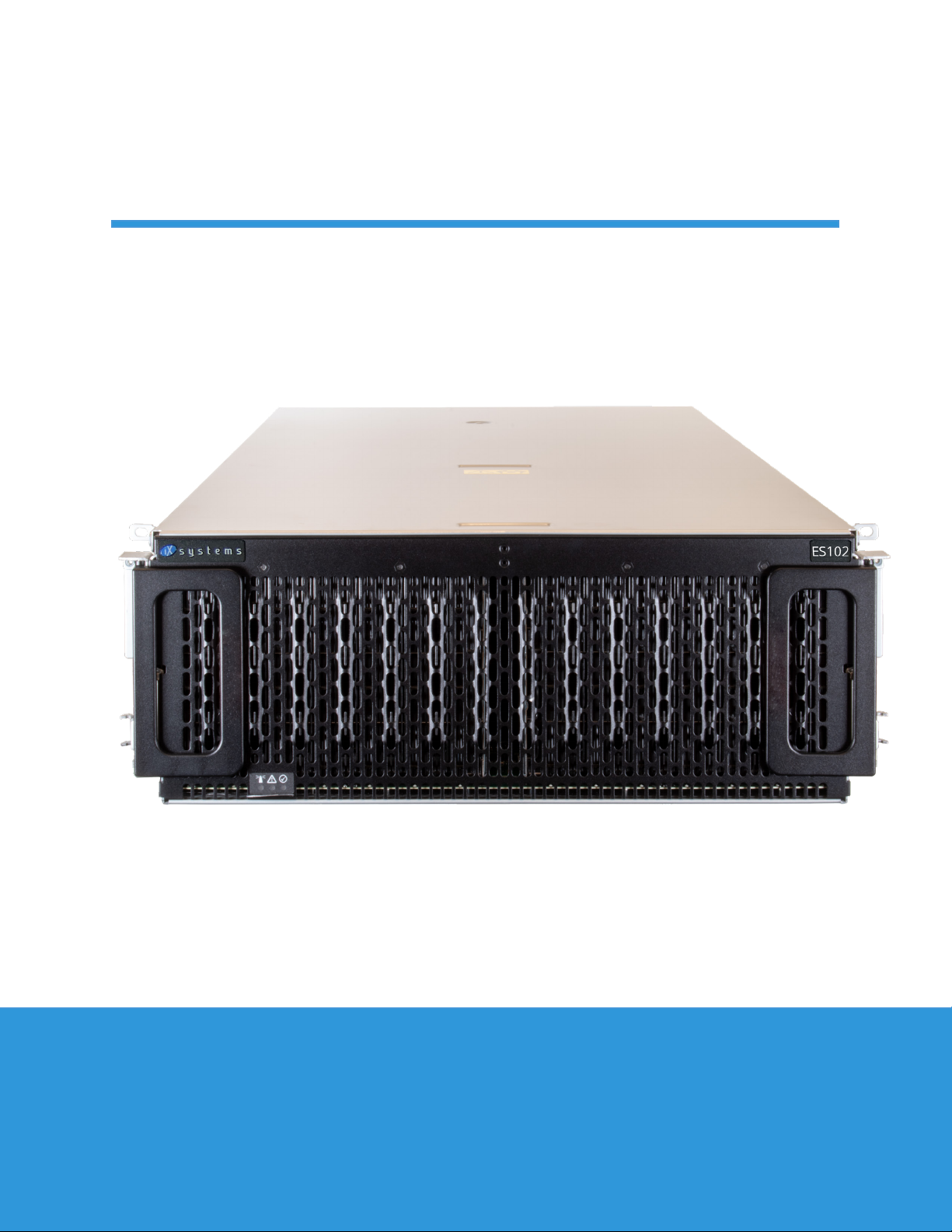
1.2 Become Familiar with the ES102
Indicators on the front panel show identication and status. The fault indicator is on during the initial power-on self-
test (POST) or when the TrueNAS software has issued an alert. These indicators are duplicated on the back panel.
• Enclosure Fans (1)
• First Power Supply (2)
• Second Power Supply (3)
• SAS Connection Indicators (4)
• Enclosure Indicators (5)
• Controller Management Port (not used) (6)
• HD Mini SAS3 connectors (7)
The ES102 has two expansion controllers in a side-by-side conguration.

2 Prerequisites
2.1 Safety
2.2 Tools
2.1.1 Static Discharge
2.1.2 Enclosure Size
There are additional considerations and some preparation required before installing the ES102 into a rack.
The ES102 is much larger than other Expansion Shelves sold by iXsystems. Be sure to take full safety precautions
when installing or servicing the enclosure.
Static electricity can build up in your body and discharge when touching conductive materials. Electrostatic Dis-
charge (ESD) is very harmful to sensitive electronic devices and components. Keep these safety recommendations in
mind before opening the system case or handling system components:
1. Turn o the system and remove the power cable before opening the system case or touching any internal com-
ponents.
2. Place the system on a clean, hard work surface like a wooden tabletop. Using an ESD dissipative mat can also
help protect the internal components.
3. Touch the metal chassis with your bare hand before touching any internal component, including components not
yet installed in the system. This redirects static electricity in your body away from the sensitive internal components.
Using an anti-static wristband and grounding cable is another option.
4. Store all system components in anti-static bags.
More details about ESD and preventative tips can be found at https://www.wikihow.com/Ground-Your-
self-to-Avoid-Destroying-a-Computer-with-Electrostatic-Discharge
These tools are needed to properly install the ES102 in a compatible rack:
Long T15 screwdriver and a #2 Philips head screwdriver.
These items are not required, but can be useful when installing the ES102:
Tape measure, level, at head screwdriver, and cable ties.
The ES102 weighs 70 lbs unloaded and requires a minimum of two people to lift.
Do not attempt to lift the ES102 when it is fully populated with drives! The total weight of a fully-populated sys-
tem is over 260 lbs. When removing a fully-populated system from a rack, remove the drives before de-racking the
enclosure.
You will need at least 37.5” (952.5mm) empty space in front of a racked ES102 to fully extend the enclosure to ac-
cess all drive bays. Due to the weight of the enclosure, this can be a tipping hazard for the rack. Be sure to follow all
tipping prevention instructions recommended by your rack provider before installing the ES102.

3 ES102 Rail Installation Procedures
3.1 Enclosure Rails
Each rack rail includes an inner chassis rail that must be removed. Extend the innermost rail as shown below until
it clicks into place and the metal safety catch is fully exposed. Push the safety catch in and continue to pull out the
innermost rail until it is completely free from the rack rail. Repeat the process for the second rail.
The chassis rails are attached to each side of the ES102. Align the chassis rail keyholes with the posts on the side
of the ES102. Slide the rail towards the rear of the system until the metal tab clicks and locks the rail in place. Use
three of the included short M4 Philips screws to secure the rail to the ES102. Repeat this process on the other side.
The Cable Management Arm attach point will be at the back of the system.
There are several steps to installing the rails on both the ES102 and inside the rack. The chassis rails need to be
separated from the larger rack rails and installed on the ES102. Then, the rack rails need to be tted inside the rack.
Additional components for securing the ES102 drive cover and latching the unit in the rack are also installed before
the ES102 can be reattached to the rack rails and installed in the rack.
PRESS PULL
M4 Screw M4 Screw M4 Screw
2.3 Rack Requirements
At minimum, the ES102 requires 4U of space in a EIA-310 compliant rack that is 47.24” (1200mm) deep, from frame
to frame. The vertical rack rails need to be spaced between 31.5” - 36.2” (800mm - 920mm) apart to properly install
the ES102 rails. It is recommended to adjust the front vertical rack rails to be as close to the front of the rack as
possible to prevent the cable management arms (CMAs) from protruding from the back of the rack. The system with
CMAs attached is 47.1 (1197mm) deep.
The rack must be a standard 17.72” - 18.31” (450mm - 465mm) wide, although a minimum 33.5” (850mm) cabinet
width allows for using a zeroU PDU with the enclosure. Narrower cabinets could require a rack-mounted PDU to
properly allow the enclosure to be fully installed into the rack and properly cabled with the included Cable Manage-
ment Arms.
For 52U racks, iXsystems recommends the AR3357X674. In a 42U rack, iXsystems recommends the AR3350 APC. It
is recommended to use the lowest 4U of available space in the rack to better balance the weight of the system with
other equipment installed in that rack.

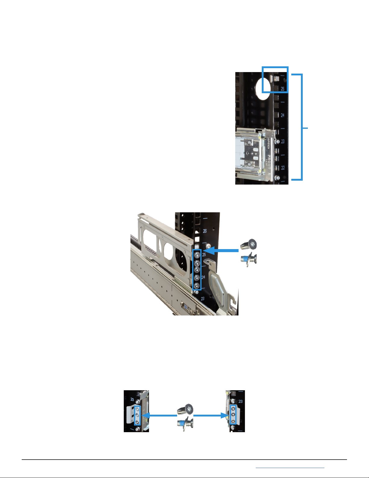
The ES102 occupies 4U of rack space. The front rail pins are mounted to the bottom-most attach points of this 4U
and back rail pins are mounted to one space above the bottom-most attach points of the 4U. The rails are stamped
for left side (L) and right side (R) of the rack, according to your perspective when facing the rack.
3.2 Rack Rails
When installed correctly, the front and rear of the rail will be level and the inner part of the rail with the gray bearing
sleeve is facing the inside of the rack. Use the same procedure to install the other rail, but make sure both left and
right rails are installed at the same height mounting holes in each rack post.
The rear of the rail can slide to accomodate racks that
have 32 -36 inches of space between the front and rear
rack posts.
Align the rear rail pins with the mounting holes in the rack
and push forward until the blue release catch clicks into
place over the rack. Note the rear rail pins install into one
mounting hole higher than the front rail pins. If available,
use a level to ensure the front and back of the rail are
even.
Install the front of the rail rst. Align the rail pins with the
mounting holes in the rack and push forward until the
front latch clicks into place on the rack.
Double check that an additional 2U of rack space is avail-
able above the rail.
Use three of the included washers and T15 M5 screws to secure the rear of the rail to the rack post.
T15 M5
Screws
4 Cover Retention
4.1 Attach Cage Nuts
4.2 Install Alignment Brackets
5 Latch Plates
Installing the cover retention components allows for holding the cover in place when the unit is slid forward out of
the rack, greatly simplifying drive bay access. This requires installing alignment brackets over the rear of the rack
rails and cage nuts at the front of the system for the included cover retention screws.
You will need two of the included square cage nuts.
Take a cage nut and add it the topmost rack mounting
hole of the required 4U of space. A at head screwdriver
can be helpful to push the cage nut “wings” into the rack
mounting hole.
The nut will be inside the rack, with the attach “wings” ori-
ented horizontally. Repeat this process for the other rack
post and make sure both cage nuts are installed parallel
rack mounting holes.
Place the included Cover Alignment Bracket over the rail and align it with the mounting holes on the rear of the rack
rail. The groove in the bracket must be pointed toward the inside of the rack. Use ve washers and T15 M5 screws to
secure the bracket to the rear of the rack rail.
The latch plates are used to hold the enclosure in place when it is fully inserted into the rack. They attach to the
front of the rack rails and also help secure the rails to the rack. Align the plate over the three holds between the rack
rail front mounting pins. The ange must be pointed to the outside of the rack. Use three T15 M5 screws to secure
the latch plate, rack post, and rack rails together.
Use the same procedure to install the second alignment brack to the other rail. Make sure that the grooves on the
top of both brackets are pointed inside the rack. The ES102 cover will slide into these grooves when it is pushed into
the rack.
Use the same procedure to install the second plate on the front of the other rail. Make sure that both anges on the
latch plates are pointed to the outside of the rack.
4U
T15 M5
Screws
T15 M5
Screws

6 Mount the Unit in the Rack
Caution: Two people are required to safely lift the chassis for rack installation or removal. It is recommended
to have a third person help align the enclosure rails with the rack rails. Do not install drives until after the chassis
has been installed in the rack, and remove all drives before removing the chassis from the rack.
Locate the metal safety catches on each chassis rail and squeeze them into the chassis (1). Holding the safety catch-
es in place, push the chassis into the rack (2) until the chassis latches are touching the rail latch plates.
Slide the middle part of the rack rails out of the rack until they click into place (1). Make sure the inner bearing
sleeve is also slid as far forward as possible (2).
Caution: Do not use the front handles to lift the ES102! These handles are only intended for unlatching and slid-
ing the enclosure after it has been attached to the rack rails. They cannot support the weight of the system.
Lift the ES102, align the attached cabinet rails with the middle rack rails, and push the ES102 into the rack rails until
it stops.

6.1 Attach Cover Retention Screws
To hold the ES102 cover in place when the system is slid out of the rack, attach the two included Philips head reten-
tion screws through the left and right cover retention holes and into the installed cage nuts. Make sure both screws
are tight enough to securely hold the cover in place.
Make sure the enclosure cover slides into the Alignment Bracket grooves at the rear of the rack. To minimize any
jarring motions, softly secure the enclosure in place by swinging the front handles out (1) and gently pushing the en-
closure forward until it is fully in the rack (2). When the handles are released, the enclosure latches will catch behind
the latch plates and hold the system in the rack (3).
M5 12mm
Philips
Screw
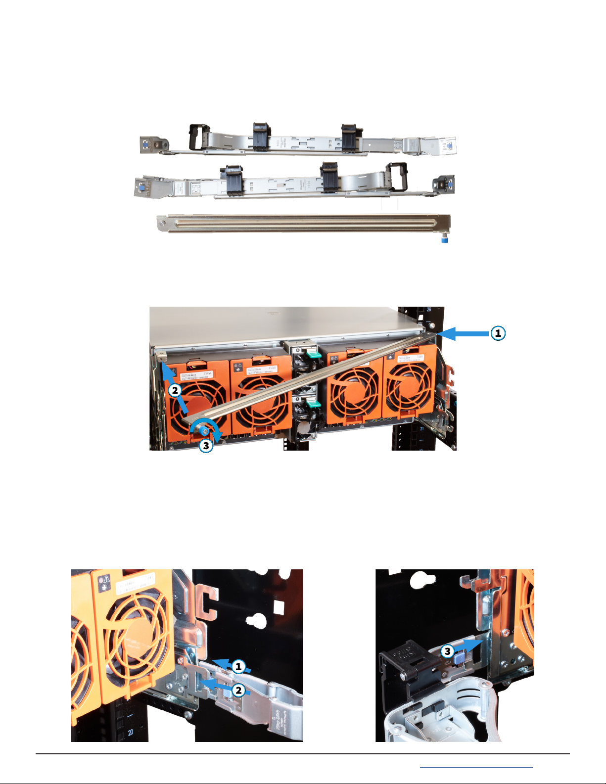
7 ES102 Cable Management Arms
The included Cable Management Arms (CMA) are required to ensure the ES102 remains properly cabled while being
slid out of the rack. There are two CMAs included with the ES102, installed on the rear of the enclosure in an Upper
(U) and Lower (L) conguration. There is also a brace included to help stabilize the CMAs and rails together.
7.2 Install Lower Cable Management Arm
There are three attach points for the lower CMA, two on the right rail and one on the left. Beginning with the right
side, insert the outermost connection post into the outer bracket until it clicks into place (1). Now align and insert
the inner post into the innermost bracket (2). Swing the back of the CMA to the left rail and insert the post into the
left bracket until it clicks into place (3).
7.1 Attach Cable Management Brace
At the back of the system, insert the brace pivot pin into the top bracket on the right rail (1). Align the brace with the
top bracket on the left rail (2) and tighten the thumbscrew until the brace is rmly in place (3).
You will need the CMA stamped Lower (L) for this procedure.
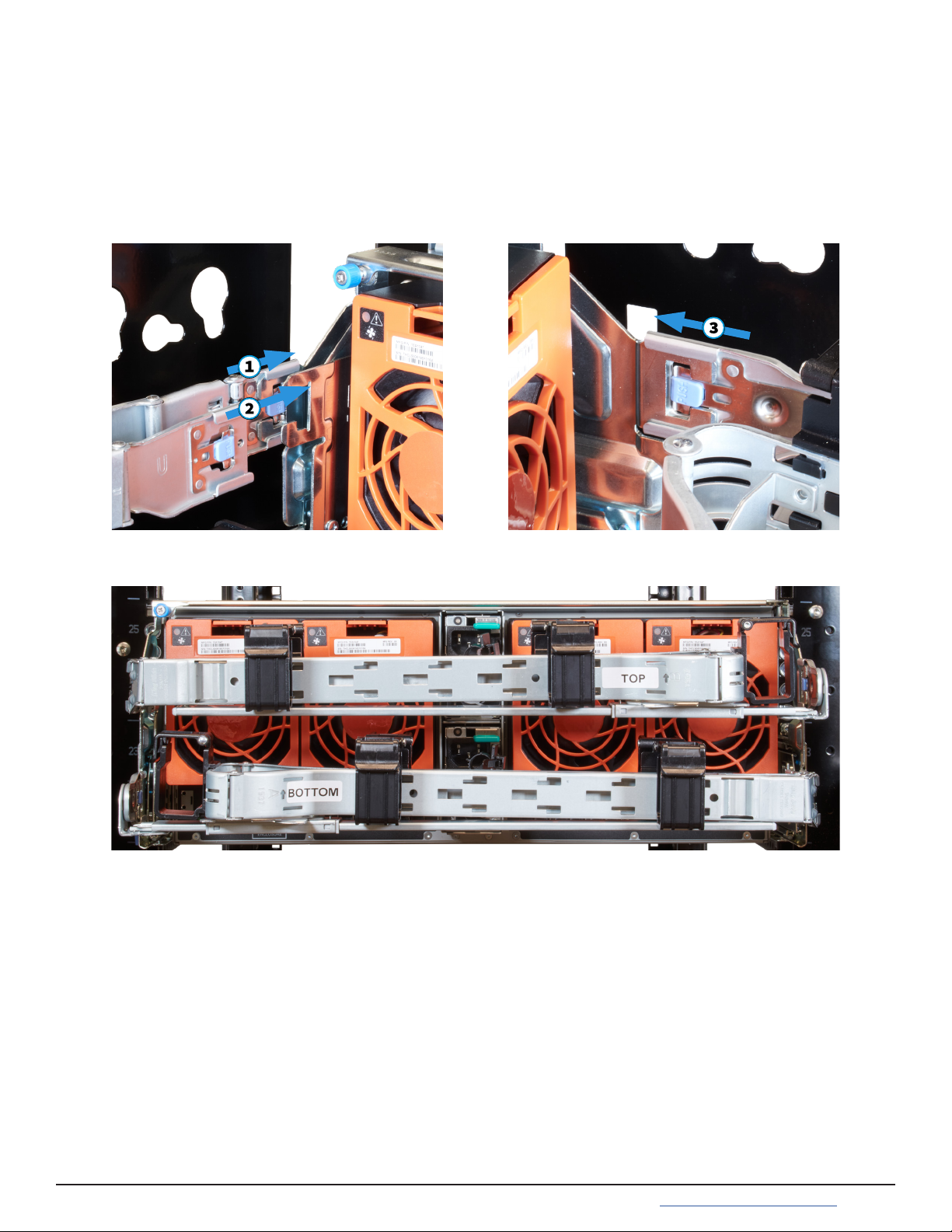
7.3 Install Upper Cable Management Arm
You will need the CMA stamped Upper (U) for this procedure.
There are three attach points for the upper CMA, two on the left rail and one on the right. Beginning with the left
side, insert the outermost connection power into the outer bracket until it clicks into place (1). Now align and insert
the inner post into the innermost bracket (2). Swing the back of the CMA to the right rail and insert the post into the
right backet until it clicks into place (3).
Before installing any drives in the ES102 or routing any cables through the CMAs, test the installation by unlatching
the enclosure and sliding it all the way forward until it clicks into place. The CMAs will fully extend behind the ES102
and the cover will remain in place, exposing the drive and component bay.
If you feel any grinding or the enclosure unexpectly stops before locking into place, don’t force the motion! Carefully
press the enclosure rail safety catches and push the enclosure back into the rack, secure it in place, and verify the
Cable Management Arms, Latch Plates, Cover Alignment Brackets, and Rails are correctly installed.
Here is how the back of the system should appear when both CMAs are properly installed:
8 Drive Installation
Do not install the drives until the enclosure has been installed in the rack. Only approved WD drives are
compatible with the ES102.
The ES102 is sold with all the drives needed to fully populate the enclosure, packaged separately. Drives are shipped
already attached to the drive clips, but in the event you need to replace a failed drive, the clip attach procedure is
included here.
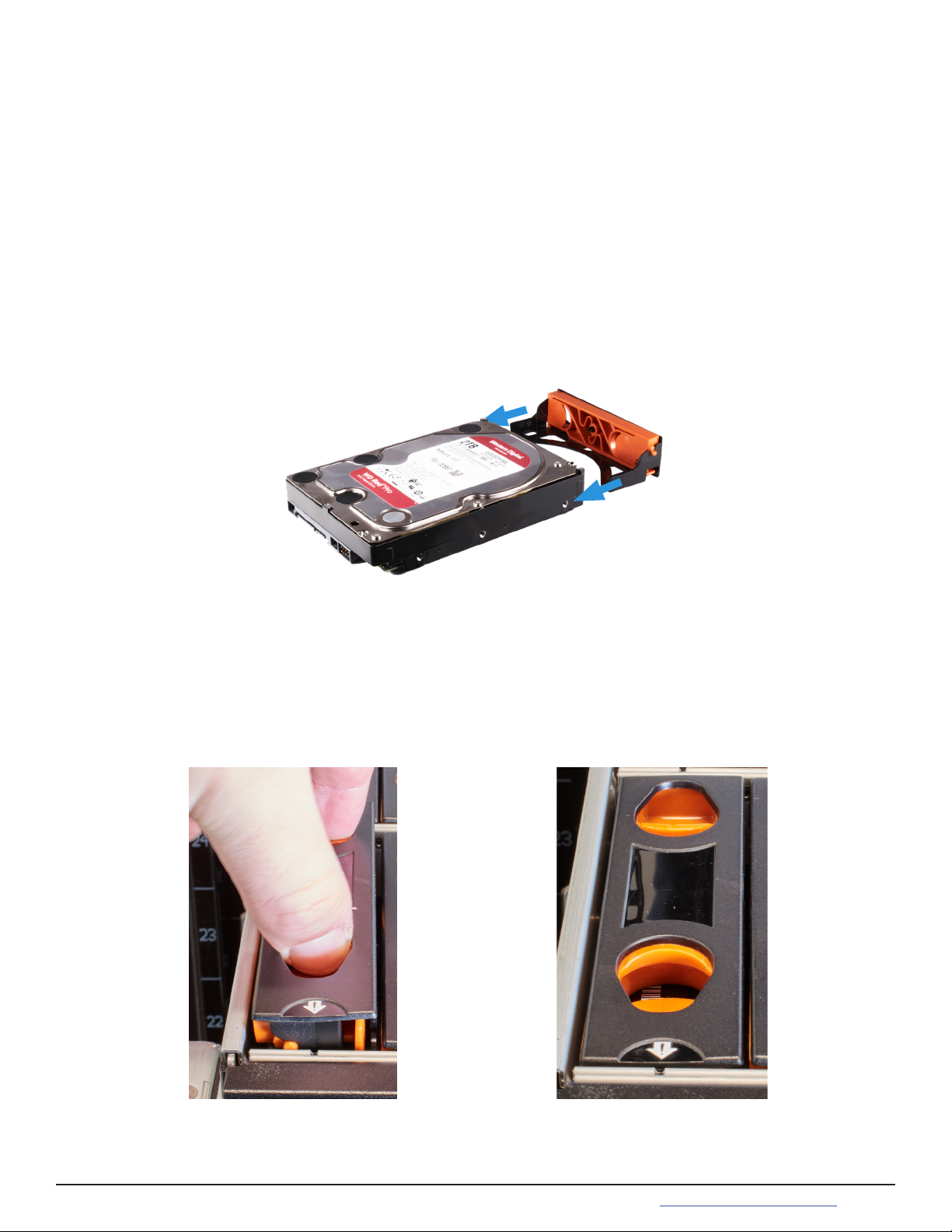
8.1 Attach Clip to Drive
8.2 Insert Drives into the Enclosure
Drives with attached clips are used to install drives in the enclosure in order from back to front.
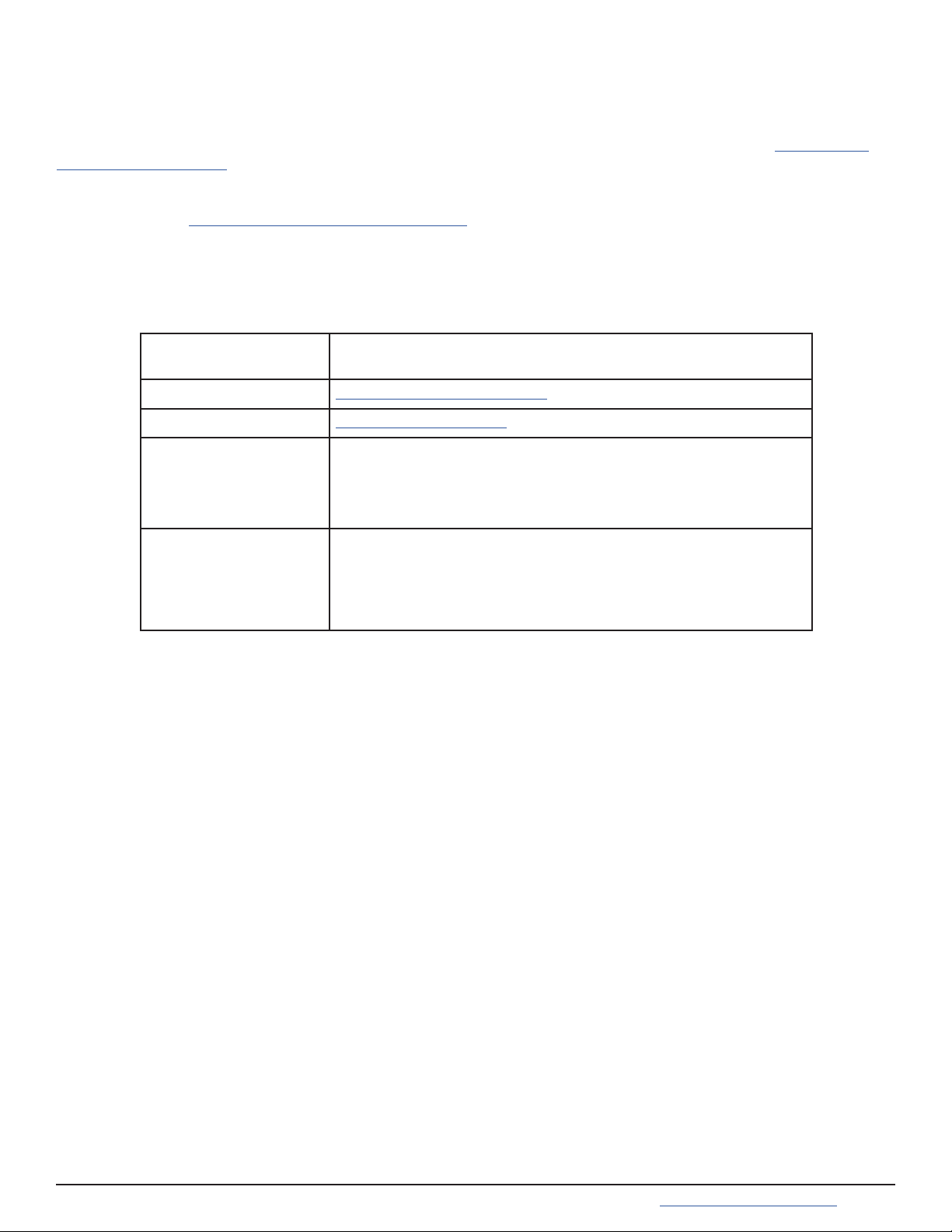
To install a drive, point the arrow on the clip towards the front of the enclosure, squeeze the orange buttons togeth-
er, and gently push the drive down into the enclosure slot. Release the orange buttons to secure the drive in place.
Make sure the drive is fully inserted into the enclosure and doesn’t extend above the top of the system. You might
need to gently work the clip into the sides of the bay to fully secure the drive in place.
ES102 drive clips t over the front of a drive and have two plastic pegs that pop into the frontmost screw holes on
the left and right sides of the drive.
Align the drive and clip so the the bottom of the clip ts over the bottom of the drive and the drive connection ports
are on the opposite end from the clip. Push the clip connection peg into place on one side of the drive and then
gently ex the clip over the drive until the other connection peg pops into place.
For proper airow, be sure to follow this drive installation order:
Starting with the row at the back of the ES102 drive bay, install the drives from left to right. When that row is lled,
move to the next row forward and proceed to ll the enclosure from left to right, back row to front.

9 Cabling
The ES102 only accepts 200-240v power input. Connect a power cord to the back of one power supply. Extend the
plastic retention clamp, open it, t it over the power cable, and push it down over the cable to lock it in place. Re-
peat the process to connect the second power supply and secure the cord.
9.1 Power
Do not plug the power cords into a power outlet yet.
Start by connecting cables to the various ports on the back of the ES102 and routing through the cable management
arms. Make sure to leave enough ex in the cables so that they are not pulled out of place when the enclosure in
slid out of the rack.
Service and Management ports are not used during normal operation and do not require cabling.
9.2 SAS Connections
Up to 12 ES102 systems are compatible with the M60 Unied Storage Array. A typical SAS cable connection for two
ES102s to a High Availability (HA) M60 is shown here:
SAS Ports
1-4 5-8 9-12

If the TrueNAS system is already on, then you can turn on the ES102 at any time by plugging both power cords into
PDU outlets and waiting two minutes for the drives to start.
9.3 Cable Routing
To simplify cabling with the Cable Management Arms (CMAs), swing open both arms so that they are pointed di-
rectly away from the enclosure. To do this, start with the lower arm and press the blue release catch on the left side
connector, then swing the arm to the right. Release the right side connector on the upper arm and swing it to the
left.
To open the cable retention clips, gently squeeze and lift the top of the clip.
To ensure there is enough ex in the cables to allow sliding the enclosure fully out of the rack, it is recommended
to route cables for the rst Storage Controller (left side) through the lower CMA (right side) (1). Route cables for the
second Storage Controller (right side) through the upper CMA (left side) (2). Allow plenty of ex in the cables by not
pulling them tightly through the CMAs.
When nished routing all the cables through the CMAs, close all the cable retention clips and swing the arms back
to the left and right, reconnecting each side back to the enclosure. If you see any cables getting pinched or pulled
while swinging the arms back, do not force the motion! Return to the starting position and adjust the cables to allow
more ex or avoid getting pinched.
11 Resources
The TrueNAS Documentation Hub has software conguration articles and additional hardware documentation for
TrueNAS products. It is available by clicking Guide in the TrueNAS web interface or going directly to https://www.
truenas.com/docs/hub/.
The TrueNAS Community is another great resource for collaboration and research! The friendly and helpful commu-
nity is available at https://www.truenas.com/community/.
11.1 Contacting iXsystems
For assistance, please contact iX Support:
Contact Method Contact Options
Web https://support.ixsystems.com
Email [email protected]
Telephone Monday-Friday, 6:00AM to 6:00PM Pacific Standard Time:
• US-only toll-free: 855-473-7449 option 2
• Local and international: 408-943-4100 option 2
Telephone Telephone After Hours (24x7 Gold Level Support only):
• US-only toll-free: 855-499-5131
• International: 408-878-3140
(International calling rates will apply)
Other manuals for ES102
2
Table of contents
Other TrueNAS Storage manuals

TrueNAS
TrueNAS Mini 3.0 Manual

TrueNAS
TrueNAS ES102 Manual

TrueNAS
TrueNAS X-Series Manual

TrueNAS
TrueNAS R30 Manual

TrueNAS
TrueNAS ES24 Manual

TrueNAS
TrueNAS M Series Manual

TrueNAS
TrueNAS Mini X+ Installation and operation manual

TrueNAS
TrueNAS R20A User manual

TrueNAS
TrueNAS ES60 Manual

TrueNAS
TrueNAS ES60 Manual

TrueNAS
TrueNAS ES60 Manual

TrueNAS
TrueNAS M Series Manual

TrueNAS
TrueNAS M Series User manual

TrueNAS
TrueNAS X Series Manual

TrueNAS
TrueNAS M Series Manual

TrueNAS
TrueNAS Mini R Manual

TrueNAS
TrueNAS R Series Manual

TrueNAS
TrueNAS ES24F Manual

TrueNAS
TrueNAS R Series User manual

TrueNAS
TrueNAS M Series User manual


