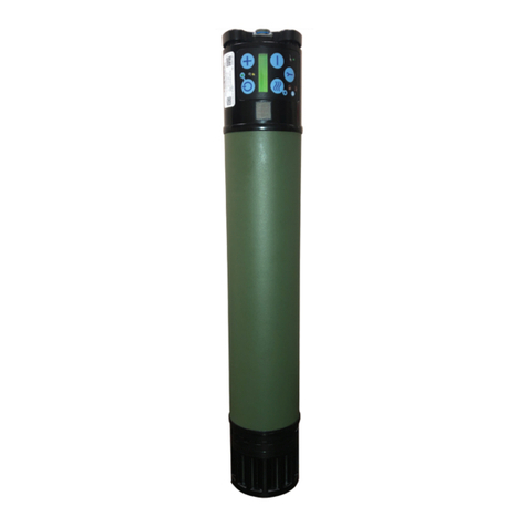
Saros 9400R-SEQ User manual

OPERATOR & SERVICE
MANUAL
Oxygen System
CAIRE Inc.
2200 Airport Industrial Dr., Ste 500
Ball Ground, GA 30107
www.CAIREmedical.com
Copyright © 2019 CAIRE Inc.. CAIRE Inc. reserves the right to discontinue its products,
or change the prices, materials, equipment, quality, descriptions, specifications and/or
processes to its products at any time without prior notice and with no further obligation or
consequence. All rights not expressly stated herein are reserved by us, as applicable.
9735-SEQ H
NSN: 6515-01-588-3083
PN 9400-SEQ
MODEL 3000

Operator & Service Manual
2| 9735-SEQ H
ISO 7000; GRAPHICAL SYMBOLS FOR USE ON
EQUIPMENT—INDEX AND SYNOPSIS
Portable operating temperature is -10C to 40C.
Base operating temperature range is 10C-40C.
Reg. # 0632
Portable humidity range is 15 to 95%. Base
humidity range is 30 to 75%. Reg. #2620
Keep away from rain, keep dry. Reg. # 0626
Name and address of manufacturer. Reg. #
3082
Date of Manufacture. Reg. #2497
Caution, consult accompanying documents.
Reg. # 0434A
Catalog Number. Reg. # 2493
Serial Number. Reg. # 2498
This way up. Reg. # 0623
Fragile, handle with care. Reg. # 0621
Stacking height. Reg #2473
ISO 7010: GRAPHICAL SYMBOLS—SAFETY COLORS
AND SAFETY SIGNS—REGISTERED SAFETY SIGNS
Keep away from open ame, re, sparks.
Open ignition source and smoking prohibited.
Reg. # P003
Do not smoke near unit or while operating
unit. Reg. # P002
Type BF applied part (degree of protection
against electric shock). Reg. # 5333
Warning. Reg. # W001
The instruction manual must be read. Reg. #
M002
INTERNAL SYMBOLS
Keep away from ammable materials, oil and
grease.
O2
Oxygen Output; The port from which the
Oxygen ows and where the tubing or
interface(standard nasal cannula) is connected.
IEC Icon for DC Power (Input) Indicates
equipment providing a particular degree of
protection against electric shock, particularly
regarding: Allowable leakage current; Reli-
ability of a proper ground connection.
Amperes (Current)
Alternating Current (AC)
WARNING: DO NOT OPERATE THIS EQUIPMENT WITHOUT FIRST READING AND UNDERSTANDING THIS MANUAL. IF
YOU ARE UNABLE TO UNDERSTAND THE WARNINGS AND INSTRUCTIONS, CONTACT YOUR EQUIPMENT PROVIDER
BEFORE ATTEMPTING TO USE THIS EQUIPMENT; OTHERWISE, INJURY OR DAMAGE MAY RESULT.
DEFINITION OF SYMBOLS PAGE / WARNING PAGE
WARNING: INDICATES A HAZARDOUS SITUATION THAT, IF NOT AVOIDED, COULD RESULT IN DEATH OR SERIOUS
INJURY.
CAUTION: Indicates a hazardous situation that, if not avoided, could result in minor or moderate injury.
NOTE: Indicates information considered important, but not hazard-related (e.g. messages relating to property damage).
SYMBOLS USED IN THE OPERATION OF SAROS
Symbols are frequently used on equipment in preference to words with the intention of reducing any possibility of misunderstand-
ing caused by language differences. Symbols can also permit easier comprehension of a concept within a restricted space.

9735-SEQ H | 3
Operator & Service Manual
Audible Alarm*;
An audible indicator is
provided to announce an audible alarm for
the following: low purity after warm up,
ow rate out of range, warm battery, battery
communication lost, and low battery.
Alert (Yellow) Indicator*: When illuminated,
this indicates an awareness condition or
Caution.
Alarm (Red) Indicator*: In Normal
Mode, when illuminated, this indicates a
Malfunction and the SAROS will stop
operating. An immediate response is
necessary and contact a Service Technician.
ON/OFF (Standby); Powers the device ON
or OFF, but does not directly disconnect the
main power.
Increase Flow Setting; Increases the ow
setting by 1.0 LPM increments or by 1 pulse
setting each time the button is pressed.
Decrease Flow Setting; Decreases the ow
setting by 1.0 LPM increments or by 1 pulse
setting each time the button is pressed.
Activates either Continuous Flow Mode or
Pulse Flow Mode Operation.
Utility; The Button that activates a utility
menu to access information or to change
settings.
External Power is Present Indicator; Indicates
the presence of external power.
Battery Status Indicator; Shows the amount
of charge remaining in the battery. When
charging, battery displays as a “Waterfall”
Effect.
21 CFR 801.15: CODE OF FEDERAL REGULATIONS
TITLE 21
Federal law restricts this device to sale by or
on the order of a physician.
COUNCIL DIRECTIVE 2012/19/EU: WASTE ELECTRICAL
AND ELECTRONIC EQUIPMENT (WEEE)
WEEE
IEC 60601-1: MEDICAL ELECTRICAL EQUIPMENT - PART
1: GENERAL REQUIREMENTS FOR BASIC SAFETY AND
ESSENTIAL PERFORMANCE
Classication; Class II Equipment, double
insulated.
Safety; Safety agency for CAN/CSA C22.2
No. 60601-1-08 M90 for medical electrical
equipment
*Alarms for the SAROS are considered information only
signals.
This product may be covered by one or more patents, US and
international. Please visit our website below for the listing of
applicable patents. Pat.: patents.gtls.io.

Operator & Service Manual
4| 9735-SEQ H
TABLE OF CONTENTS
DEFINITION OF SYMBOLS PAGE / WARNING PAGE................................................................................................... 2
INDICATIONS FOR USE ................................................................................................................................................ 8
INDICATIONS ............................................................................................................................................................... 8
CONTRAINDICATIONS ................................................................................................................................................. 8
SAFETY GUIDELINES............................................................................................................................................... 8
BATTERY SAFETY.................................................................................................................................................. 10
1.0 INTRODUCTION ................................................................................................................................................... 11
1.1 GENERAL INFORMATION ............................................................................................................................... 11
1.2 SAROS OXYGEN SYSTEM SPECIFICATIONS ................................................................................................... 12
2.0 INTRODUCTION TO YOUR SAROS OXYGEN SYSTEM ...................................................................................... 15
2.1 DESCRIPTION OF THE SAROS (9400-SEQ) ASSEMBLY—SHIPPABLE ........................................................... 15
2.2 USER CONTROLS AND SYSTEM STATUS INDICATORS................................................................................... 17
2.3 RECOMMENDED OPERATING ENVIRONMENTS............................................................................................ 19
3.0 PREPARATION FOR USE AND INSTALLATION..................................................................................................... 20
3.1 BATTERY INSTALLATION ONTO SAROS......................................................................................................... 20
3.2 LOCATING THE SAROS ................................................................................................................................... 20
3.3 SAROS PERFORMANCE VERIFICATION TEST ................................................................................................. 20
4.0 THEORY OF OPERATION ..................................................................................................................................... 21
5.0 OPERATING INSTRUCTIONS ................................................................................................................................ 26
5.1 OPERATING THE SAROS FOR THE FIRST TIME .............................................................................................. 29
6.0 OPERATOR MAINTENANCE & SERVICE .............................................................................................................. 32
6.1 CLEANING THE SAROS .................................................................................................................................. 32
6.2 ROUTINE MAINTENANCE .............................................................................................................................. 32
6.3 CLEANING OR REPLACING AIR INLET FILTER ................................................................................................ 33
6.4 REPLACING THE HEPA FILTER ........................................................................................................................ 34
6.5 RUN DEVICE AND FULLY DRAIN SAROS BATTERY........................................................................................ 35
6.6 SAROS PERFORMANCE VERIFICATION TEST ................................................................................................. 35
6.7 REPLACING THE 9V BATTERY ........................................................................................................................ 38
7.0 ALERTS, ALARMS, AND TROUBLESHOOTING TABLE ........................................................................................ 38
7.1 SYSTEM TROUBLESHOOTING GUIDE ............................................................................................................ 39
8.0 REPROGRAMMING/CALIBRATION...................................................................................................................... 40
9.0 SHIPPING AND TRANSPORTING THE SAROS ..................................................................................................... 40
10.0 STORING AND DISCARDING THE SAROS ......................................................................................................... 40

9735-SEQ H | 5
Operator & Service Manual
11.0 OVERHAUL & REPAIR ........................................................................................................................................ 41
11.1 TOOLS AND TEST EQUIPMENT .................................................................................................................... 41
11.2 MAINTENANCE AND SERVICE PARTS .......................................................................................................... 41
11.3 REPROGRAMMING AFTER OVERHAUL AND REPAIR PROCEDURES .......................................................... 42
11.4 SAROS MAIN COMPONENTS ....................................................................................................................... 42
11.5 ALARM INDICATIONS AND CODES.............................................................................................................. 43
11.6 COMPREHENSIVE TROUBLESHOOTING GUIDE........................................................................................... 47
11.7 REMOVAL PROCEDURES.............................................................................................................................. 49
11.7.1 BATTERY INTERFACE PLATE, RAIN GUARD, AND SLEEVE ....................................................................... 49
11.7.2 INLET CAP REMOVAL ................................................................................................................................ 50
11.7.3 REMOVE PCB ASSEMBLY........................................................................................................................... 53
11.7.4 PROPORTIONAL VALVE REMOVAL (5293-SEQ)........................................................................................ 54
11.7.5 COMPRESSOR FAN REMOVAL (9767-SEQ) ............................................................................................... 55
11.7.6 BATTERY CABLE REMOVAL (9201-SEQ) ................................................................................................... 56
11.7.7 RAIL REMOVAL.......................................................................................................................................... 57
11.7.8 ATF & COMPRESSOR / TANK ASSEMBLY REMOVAL ................................................................................ 58
11.8 INSTALLATION PROCEDURES....................................................................................................................... 59
11.8.1 GENERAL PROCEDURE .............................................................................................................................. 59
11.8.2 ATF & COMPRESSOR/PRODUCT TANK INSTALLATION............................................................................. 60
11.8.3 RAIL INSTALLATION................................................................................................................................... 62
11.8.4 BATTERY CABLE INSTALLATION ............................................................................................................... 63
11.8.5 COMPRESSOR FAN REPLACEMENT........................................................................................................... 65
11.8.6 PROPORTIONAL VALVE REPLACEMENT (5293-SEQ)................................................................................ 65
11.8.7 INSTALLATION OF PCB ASSEMBLY............................................................................................................ 66
11.8.8 POWER CONNECTOR REPLACEMENT (9766-SEQ) ................................................................................... 69
11.8.9 MEMBRANE PANEL REPLACEMENT (9731-SEQ) ...................................................................................... 70
11.8.10 INLET CAP INSTALLATION (SP9756-SEQ) ................................................................................................ 71
11.8.11 INSTALLATION OF THE SLEEVE & BATTERY INTERFACE PLATE ............................................................. 73
12.0 SERVICE RECORDS & RETENTION..................................................................................................................... 75
12.1 RECORD HOURS OF OPERATION AND SOFTWARE VERSION..................................................................... 75
12.2 SERVICE AND MAINTENANCE RECORD ...................................................................................................... 76
ILLUSTRATIONS
Figure 2-1. SAROS Components ..................................................................................................................... 15
Figure 2-2. SAROS Components ..................................................................................................................... 16
Figure 3-1. Battery Installation ...................................................................................................................... 20
Figure 4-1. System Board Diagram ................................................................................................................ 22
Figure 5-1. Battery Installation ...................................................................................................................... 28
Figure 6-1. SAROS Components ..................................................................................................................... 33
Figure 6-2. Remove Cover .............................................................................................................................. 33
Figure 6-3. Filter.............................................................................................................................................. 34
Figure 6-4. Reinstall O2 Fitting/HEPA Filter................................................................................................... 34
Figure 6-5. Replacing 9V battery ................................................................................................................... 38
Figure 11-1. Inside SAROS .............................................................................................................................. 42
Figure 11-2. Removal of the three BIP screws............................................................................................... 49
Figure 11-3. Removal of the three Rain Guard Screws................................................................................. 49
Figure 11-4. Removal of the Rain Guard ....................................................................................................... 49
Figure 11-5. Removal of Sleeve Alignment Ring .......................................................................................... 49
Figure 11-6. Fiberglass Sleeve ........................................................................................................................ 50
Figure 11-7. Air Inlet Cover Removal............................................................................................................. 50
Figure 11-8. Filter Screen & 9V Removal ....................................................................................................... 50
Figure 11-9. Inlet Cap Screw Removal ........................................................................................................... 50
Figure 11-10. Oxygen Outlet Tube Disconnect. ............................................................................................ 51
Figure 11-11. Front Panel Flex Cable Disconnect .......................................................................................... 51
Figure 11-12. Thermistor Connector and 9V Battery Connector ................................................................. 51

Operator & Service Manual
6| 9735-SEQ H
Figure 11-13. Inlet Cap Power........................................................................................................................ 51
Figure 11-14. Tube Disconnect ....................................................................................................................... 52
Figure 11-15. Inlet Cap Removal .................................................................................................................... 52
Figure 11-16. Detach Top Strut ...................................................................................................................... 52
Figure 11-17. Battery Power Wires for Battery Interface ............................................................................. 53
Figure 11-18. Communication Connector for Battery Interface .................................................................. 53
Figure 11-19. ATF Thermistor Disconnect...................................................................................................... 53
Figure 11-20. PCB Assembly ........................................................................................................................... 54
Figure 11-21. Proportional Valve Wire .......................................................................................................... 54
Figure 11-22. Proportional Valve Tube .......................................................................................................... 54
Figure 11-23. Replace Proportional Valve ..................................................................................................... 54
Figure 11-24. Remove Compressor Fan wire ................................................................................................. 55
Figure 11-25. Lift the Proportional Valve ...................................................................................................... 55
Figure 11-26. Compressor Fan........................................................................................................................ 55
Figure 11-27. Hall Effect Sensor ..................................................................................................................... 56
Figure 11-28. Remove Wire Sleeve ................................................................................................................ 56
Figure 11-29. Cable Ties and Rails.................................................................................................................. 56
Figure 11-30. Cable Ties and Struts................................................................................................................ 57
Figure 11-31. Left Strut................................................................................................................................... 57
Figure 11-32. Right Strut ................................................................................................................................ 57
Figure 11-33. Kapton Tape ............................................................................................................................. 58
Figure 11-34. Exhaust tube............................................................................................................................. 58
Figure 11-35. Cable Ties.................................................................................................................................. 58
Figure 11-36. Silicone tubing ......................................................................................................................... 58
Figure 11-37. ATF ports................................................................................................................................... 59
Figure 11-38. ATF bulkhead ........................................................................................................................... 59
Figure 11-39. Thread Locking Procedure....................................................................................................... 59
Figure 11-40. Cable tie installation................................................................................................................ 59
Figure 11-41. ATF Bulkhead ........................................................................................................................... 60
Figure 11-42. Align ......................................................................................................................................... 60
Figure 11-43. ATF caps .................................................................................................................................... 60
Figure 11-44. Down pipe Hose....................................................................................................................... 60
Figure 11-45. Cap ............................................................................................................................................ 61
Figure 11-46. Cable Ties.................................................................................................................................. 61
Figure 11-47. Open SAROS ............................................................................................................................. 61
Figure 11-48. Open SAROS ............................................................................................................................. 62
Figure 11-49. Right Strut ................................................................................................................................ 62
Figure 11-50. Route ATF wires ....................................................................................................................... 62
Figure 11-51. Secure ....................................................................................................................................... 62
Figure 11-52. Cable Tie Knots......................................................................................................................... 63
Figure 11-53. Wire Sleeve............................................................................................................................... 63
Figure 11-54. Secure Battery Wires................................................................................................................ 64
Figure 11-55. Slack .......................................................................................................................................... 64
Figure 11-56. Secure ATF ................................................................................................................................ 64
Figure 11-57. Fan ............................................................................................................................................ 65
Figure 11-58. Compressor Fan Wire............................................................................................................... 65
Figure 11-59. Proportional Valve ................................................................................................................... 65
Figure 11-60. Secure ....................................................................................................................................... 66
Figure 11-61. Connect..................................................................................................................................... 66
Figure 11-62. Screws ....................................................................................................................................... 66
Figure 11-63. Secure ....................................................................................................................................... 67
Figure 11-64. Connect..................................................................................................................................... 67
Figure 11-65. Fan Connector .......................................................................................................................... 67
Figure 11-66. Flow Tube ................................................................................................................................. 68
Figure 11-67. Tighten...................................................................................................................................... 68
Figure 11-68. Tighten...................................................................................................................................... 68
Figure 11-69. Cable Ties.................................................................................................................................. 69
Figure 11-70. Top strut ................................................................................................................................... 69
Figure 11-71. Remove screws ......................................................................................................................... 69
Figure 11-72. Power Connector ..................................................................................................................... 69
Figure 11-73. Peel ........................................................................................................................................... 70
Figure 11-74. Clean ......................................................................................................................................... 70

9735-SEQ H | 7
Operator & Service Manual
TABLES
Table 1-1. SAROS Specifications ..................................................................................................................... 12
Table 1-2. Pulse Mode Specifications............................................................................................................. 13
Table 1-3. Bolus Volume and Breath Rates.................................................................................................... 13
Table 1-4. Power Accessory Specifications..................................................................................................... 13
Table 1-5. Battery Specifications .................................................................................................................... 13
Table 1-6. Independent Safety Testing ......................................................................................................... 14
Table 1-7. SAROS ............................................................................................................................................ 14
Table 2-1. User Controls and Indicators......................................................................................................... 17
Table 2-2. Recommended Operating Environments..................................................................................... 19
Table 4-1. Battery Pack ................................................................................................................................... 24
Table 5-1. Typical New Battery Operating Time............................................................................................ 27
Table 5-2. Minimum Remaining Time on Battery ........................................................................................ 28
Table 5-3. Pulse Settings ................................................................................................................................. 30
Table 5-4. Utility Menu Screens...................................................................................................................... 31
Table 6-1. Routine Maintenance ................................................................................................................... 32
Table 7-1. Alarm Levels................................................................................................................................... 38
Table 7-2. System Troubleshooting Guide..................................................................................................... 39
Table 10-1. Storage Environment .................................................................................................................. 40
Table 11-1. Maintenance and Service Parts................................................................................................... 41
Table 11-2. Alarm Indications and Codes ...................................................................................................... 43
Table 11-3. Troubleshooting Guide................................................................................................................ 47
Table 12-1. Log the Results............................................................................................................................. 75
Table 12-2. Sample SAROS Maintenance Record .......................................................................................... 76
Figure 11-75. Remove PSA cover.................................................................................................................... 70
Figure 11-76. Apply new User Panel.............................................................................................................. 70
Figure 11-77. O-ring attached........................................................................................................................ 71
Figure 11-78. Inlet Caps .................................................................................................................................. 71
Figure 11-79. Breach Tube.............................................................................................................................. 71
Figure 11-80. Power Harness Wires ............................................................................................................... 71
Figure 11-81. Flex cable .................................................................................................................................. 72
Figure 11-82. Ambient Air Thermistor........................................................................................................... 72
Figure 11-83. Oxygen Outlet Tube................................................................................................................. 72
Figure 11-84. Inlet Cap mounting screws ...................................................................................................... 72
Figure 11-85. 9V battery................................................................................................................................. 73
Figure 11-86. Align covers and tighten ......................................................................................................... 73
Figure 11-87. Slide Sleeves ............................................................................................................................. 73
Figure 11-88. Second sleeve ........................................................................................................................... 73
Figure 11-89. Battery Interface Assembly...................................................................................................... 74
Figure 11-90. Attach ....................................................................................................................................... 74
Figure 11-91. Align ......................................................................................................................................... 74
APPENDIX A
A-1. SAROS Performance Verification Checklist............................................................................................ 77

Operator & Service Manual
8| 9735-SEQ H
INDICATIONS FOR USE
SAROS OXYGEN SYSTEM IS INDICATED FOR THE ADMINISTRATION OF SUPPLEMENTAL OXYGEN. THE DEVICE
IS NOT INTENDED FOR LIFE SUPPORT NOR DOES IT PROVIDE ANY PATIENT MONITORING CAPABILITIES.
A PHYSICIAN HAS PRESCRIBED A SPECIFIC OXYGEN FLOW SETTING TO MEET AN INDIVIDUAL’S NEEDS.
OXYGEN FLOW SETTINGS SHOULD BE ADJUSTED ONLY UNDER THE DIRECTION OF A PHYSICIAN.
WARNING: FEDERAL U.S. LAW RESTRICTS THIS DEVICE TO SALE BY OR ON THE ORDER OF A PHYSICIAN.
INDICATIONS
WARNING: IN CERTAIN CIRCUMSTANCES, THE USE OF NON-PRESCRIBED OXYGEN CAN BE HAZARDOUS. THIS
DEVICE SHOULD ONLY BE USED UNDER THE DIRECTION OF A PHYSICIAN OR QUALIFIED CLINICIAN.
NOT FOR USE IN THE PRESENCE OF FLAMMABLE ANESTHETICS.
AS WITH ANY ELECTRICALLY POWERED DEVICE, THE USER MAY EXPERIENCE PERIODS OF NON-OPERATION AS
A RESULT OF ELECTRICAL POWER INTERRUPTION, OR THE NEED TO HAVE THE SAROS SERVICED BY A QUALIFIED
TECHNICIAN. SAROS IS NOT APPROPRIATE FOR ANY PATIENT WHO WOULD EXPERIENCE ADVERSE HEALTH CONSE-
QUENCES AS THE RESULT OF SUCH TEMPORARY INTERRUPTION.
USE OF AN OXYGEN MASK IS CONTRAINDICATED DUE TO THE POSSIBILITY OF REBREATHING EXHALED CARBON
DIOXIDE.
WARNING: EXHAUST GAS MAY REACH HIGH TEMPERATURES DURING NORMAL OPERATIONS. USE CAUTION TO
AVOID TOUCHING THE EXHAUST PORT OF THE SAROS WHILE IN USE.
NOTE: Auditory alarms may not be heard in noisy environments and/or in tactical mode. Care providers must rely on visual indications
to determine if there are any alarms or other system malfunctions. Care providers should monitor the SAROS for any alarm conditions.
CONTRAINDICATIONS
SAFETY GUIDELINES
These are Warnings and Cautions that apply to hazards or unsafe practices that could result in serious injury or property damage.
WARNING: FEDERAL U.S. LAW RESTRICTS THIS DEVICE TO SALE BY OR ON THE ORDER OF A PHYSICIAN.
WARNING: DO NOT USE SAROS IF IT HAS A DAMAGED POWER CORD OR PLUG.
WARNING: DO NOT DROP OR INSERT ANY OBJECTS INTO ANY OPENING ON THE DEVICE.
WARNING: DO NOT BLOCK THE AIR INLET OR THE EXHAUST VENT OF THE SAROS WHEN IT IS ON A SOFT SURFACE,
SUCH AS A LITTER, BED, CHAIR, CARPET, COUCH OR VEHICLE SEAT.
WARNING: DO NOT COVER THE DEVICE WITH A BLANKET, TOWEL OR SHEET, ETC.
WARNING: DO NOT STORE THE SAROS WITH THE BATTERY INSTALLED IN THE UNIT.
WARNING: DO NOT REMOVE THE COVER. THERE ARE NO USER-SERVICEABLE PARTS INSIDE THE DEVICE. ONLY
QUALIFIED SERVICE PERSONNEL SHOULD REMOVE THE COVER OF THE DEVICE.

9735-SEQ H | 9
Operator & Service Manual
WARNING: DO NOT MODIFY THIS EQUIPMENT WITHOUT AUTHORIZATION OF THE MANUFACTURER.
WARNING: DO NOT OPERATE THE DEVICE, COMPONENTS OR ACCESSORIES ON WET SURFACES OR IN STANDING
WATER AND DO NOT SUBMERSE IN WATER.
CAUTION: Indicates a hazardous situation that, if not avoided, could result in minor or moderate injury.
CAUTION: Keep SAROS and the power cord away from hot surfaces or open flames.
CAUTION: SAROS should be located in a well-ventilated area to allow for adequate air intake.
CAUTION: Avoid the intake of airborne pollutants, smoke and fumes.
CAUTION: ONLY use this device with accessories specified by, or recommended by CAIRE Inc.
CAUTION: If SAROS has been dropped, damaged or exposed to water, please contact a qualified technician for
inspection or possible repair of the device.
CAUTION: When using SAROS in any vehicle, be sure it is properly secured, belted or restrained.
CAUTION: LOCATE OXYGEN SUPPLY TUBING AND ALL POWER CORDS IN A MANNER TO PREVENT TRIPPING
HAZARDS.
CAUTION: DO NOT PLACE THE SAROS IN A SMALL, ENCLOSED SPACE, SUCH AS A BATHROOM, CLOSET, BAG OR BOX
WITH THE OXYGEN CANNULA OR TUBING LEADING OUT OF THE ENCLOSED SPACE.
CAUTION: DO NOT EXPOSE THE DEVICE TO TEMPERATURES OUTSIDE OF THE SPECIFIED RANGE OF OPERATING OR
STORAGE TEMPERATURES AS THIS MAY DAMAGE THE DEVICE.
NOTE: THIS DEVICE DOES EXHAUST NITROGEN GAS. HOWEVER, THIS EXHAUST IS NOT SUFFICIENT TO DISPLACE OXYGEN IN THE OP-
ERATING ENVIRONMENT. NO ADDITIONAL SAFETY PRECAUTIONS NEED TO BE TAKEN TO ACCOUNT FOR THE NITROGEN EXHAUST.
NOTE: PROTECT ELECTRICAL POWER CORDS FROM SHARP EDGES OR ELECTRICAL SHOCK AND SERIOUS PHYSICAL INJURY MAY
OCCUR.
NOTE: ONLY USE THE CAIRE INC. SUPPLIED AC POWER ADAPTER AND 24 VDC CABLE WITH THE SAROS. USE OF ANY OTHER AC POWER
ADAPTER OR DC CABLE MAY BE HAZARDOUS, CAUSE SERIOUS DAMAGE TO THE SAROS AND WILL VOID THE WARRANTY.
NOTE: AVAILABILITY OF AN ALTERNATE, OR BACK-UP, SOURCE OF SUPPLEMENTAL OXYGEN IS RECOMMENDED IN CASE OF A POWER
OUTAGE OR A MECHANICAL FAILURE OF THE DEVICE.

Operator & Service Manual
10 | 9735-SEQ H
BATTERY SAFETY
WARNING: DO NOT DISASSEMBLE, PUNCTURE, OR CRUSH THE BATTERY. BATTERY ELECTROLYTES MAY BE TOXIC IF
SWALLOWED AND CAN BE HARMFUL TO SKIN AND EYES. KEEP THE BATTERY AWAY FROM CHILDREN.
WARNING: DO NOT SHORT-CIRCUIT THE BATTERY’S METAL CONTACTS WITH METALLIC OBJECTS, SUCH AS KEYS OR
COINS. THIS MAY CAUSE SPARKS OR EXCESSIVE HEAT TO BE GENERATED.
WARNING: USE OF A DAMAGED BATTERY MAY CAUSE PERSONAL INJURY.
WARNING: THE BATTERY MAY EXPLODE AND CAUSE POTENTIAL INJURY IF EXPOSED TO A FIRE, OR DISPOSED OF IN
A FIRE.
WARNING: EXPOSING THE BATTERY TO WATER OR OTHER LIQUIDS MAY CAUSE PERSONAL INJURY.
CAUTION: DO NOT EXPOSE THE BATTERY TO TEMPERATURES ABOVE 140° F (60°C), SUCH AS IN A VEHICLE PARKED
IN THE SUN ON A HOT DAY.
CAUTION: IT IS NOT RECOMMENDED THAT THE BATTERY IS CHARGED BELOW 41° F (5° C) OR ABOVE 104° F (40° C).
CAUTION: ONLY USE THE BATTERY FOR ITS INTENDED PURPOSE.
CAUTION: PUSH LOCKING/UNLOCKING BUTTON BEFORE BATTERY INSTALLATION.

9735-SEQ H | 11
Operator & Service Manual
1.0 INTRODUCTION
1.1 GENERAL INFORMATION
This manual will familiarize you with information regarding the SAROS Oxygen System, Model 3000.
INTRODUCTION
The SAROS Oxygen System, Model 3000 with autoSAT®Technology (hereafter referred to as SAROS) is a portable medical
device used to extract oxygen from the atmosphere, concentrate it to greater than 90% and ow it through the oxygen outlet port.
The device will operate in Continuous ow or Pulse ow modes. In Continuous Flow Mode the oxygen is provided at a constant
ow rate of 1, 2, or 3 LPM. In Pulse ow Mode, oxygen is supplied in a bolus at the beginning of each inspiration, providing a
selectable range setting of ow between 16 ml and 96 ml, in increments of 16 ml.
SAROS is BTP (Body, Temperature, and Pressure) compensated. It delivers oxygen by accounting for difference between ambient
conditions and those found in the patient’s lungs (37°C).
SAROS operates from external AC power, 24VDC or from a rechargeable Battery. The system includes a “Smart Battery” charger
that recharges the Battery whenever the SAROS is connected to external power. The system monitors and controls both the power
source and the Battery Charger.
SAROS has a ve minute warm up/stabilization period during which no alerts or codes are to be expected.
WARRANTY
SAROS: 1 year or 1,000 hours, whichever comes rst.
Battery: 1 year.
Power Supplies: 1 year.

Operator & Service Manual
12 | 9735-SEQ H
1.2 SAROS OXYGEN SYSTEM SPECIFICATIONS
Dimensions
• With battery
• Without battery
26.80” long x 4.375” diameter (68.1 cm long x 11.1 cm diameter)
23.25” long x 4.375” diameter (59.1 cm long x 11.1 cm diameter)
Weight
• With Battery
• Without Battery
12.25 pounds (5.56 kg)
10.00 pounds (4.54 kg)
Flow Settings
• Continuous Flow
• Pulse flow
1, 2, 3 LPM
16, 32, 48, 64, 80, 96 ml
Continuous Flow Accuracy 1LPM: +/- 0.4 LPM
2LPM: +/- 10%
3LPM: +/- 10%
Oxygen concentration 93% +/- 3% for all flow settings
Maximum System Pressure 15 psig (204.7 kPa)
Oxygen Output Pressure 4.0 psig (128.9 kPa) nominal
Oxygen Concentration Status Indicator Green Light = Normal Operation
Yellow Light Flashing = Warning or Caution, less than 85% ± 3%
Red Light = Abnormal Operation, less than 70% ± 5%
Nominal Sound Level <59 dB(A)
Operating Environment
• Temperature
• Humidity
32º F to 109º F (0° to 43°C)
10% to 95%, Non-condensing, 82.4°F (28°C) Maximum Dew point
Storage Environment
• Temperature
• Humidity
-4º F to 140º F (-20° to 60°C)
Up to 95% Non-condensing
Nominal Power
3 LPM Continuous Flow ≤130 Watts
Nominal Battery operating time
at 3 LPM Continuous Flow 30 Minutes
Battery Life 80% Nominal Capacity after 200 Charge/Discharge cycles
Continuous Flow Indication Expressed in liters per minute (LPM)
Audible Alarm Indicators • Loss of Power/Hot Battery
• Low Battery/Warm Battery
• Low Oxygen Output
• No breath detection
• O2 Flow Outside Normal Limits
• Low 9V battery
• Unit Malfunction
Back-Up Alarm Power 9V Internal Battery
Filters Air Inlet Filter, HEPA and Exhaust Filter
Device Classification IEC Class I, Type BF Applied Part, IPX1
Table 1-1. SAROS Specications

9735-SEQ H | 13
Operator & Service Manual
Pulse Settings 16, 32, 48, 64, 80, 96 ml
autoSAT Technology Servo-control to maintain consistent FiO2
Trigger Sensitivity Adjustable settings of 1 (most sensitive), 2 and 3 (least sensitive)
Trigger Criteria Cannula pressure has dropped below the trigger point (typically between 0.15 – 0.45 Cm of
H2O of negative pressure)
Minimum time between breaths 1.25 seconds (max. 3 consecutive breaths)
Response to Missing Breaths Switch to Continuous Mode if no inspiration has been detected for 60 seconds with an
audible alarm.
Table 1-2. Pulse Mode Specications
Bolus Size ml (± 15%) Max Breath Rate
16 40
32 40
48 40
64 40
80 37
96 31
NOTE: At breath rate above Max Breath Rate, bolus size will be reduced proportionally.
Table 1-3. Bolus Volume and Breath Rates
AC Power Supply 24 VDC Cable
Input Voltage 100- 240 VAC, 50 – 60 Hz 20 – 28 VDC
Input Power 245 – 260 VA 10 A
Output Voltage 24 VDC -
Output Power 200 W -
Table 1-4. Power Accessory Specications
Output Voltage 14.6 VDC
Capacity 88.8 W-hours
Battery Life 80% Nominal Capacity after 200 Charge/Discharge cycles
Battery Recharge Time 2.4 hours to achieve 80% capacity from a fully discharged battery
Table 1-5. Battery Specications

Operator & Service Manual
14 | 9735-SEQ H
SAROS System and SAROS Concentrator, Model 3000
Safety IEC 60601-1 :1988 + A1 :1991 + A2 :1995 + Corrigendum (6/95) EN 60601-1(1990) +
A1(1993) + A2(1995) + A12(1993) + A13(1996) + Corrigenda (7/94)
Electromagnetic Compatibility FCC 15B (Sec. 107 & 109), EN55011, EN60601-1-2 :2001, EN6100-3-2, EN61000-3-3,
IEC61000-4-2, IEC61000-4-3, IEC61000-4-4, IEC61000-4-5, IEC61000-4-6, IEC61000-4-8,
IEC61000-4-11, IEC 60601-1- 2 :2001, RTCA DO 160
AC Power Supply
Safety IEC 60601-1:1988 + A1:1991 + A2:1995
Electromagnetic Compatibility FCC 15B (Sec. 107 & 109), EN55011, EN60601-1-2 :2001, EN6100-3-2, EN61000-3-3,
IEC61000-4-2, IEC61000-4-3, IEC61000-4-4, IEC61000-4-5, IEC61000-4-6, IEC61000-4-8,
IEC61000-4-11, EN55014-1
24 VDC Cable
Safety Portions of IEC 60601-1:1988 + A1:1991 + A2:1995
Electromagnetic Compatibility FCC 15B (Sec. 109), EN55011, EN60601-1-2 :2001, IEC61000-4-2, IEC61000-4-3, IEC61000-
4-4, IEC61000- 4-6, IEC 60601-1-2 :2001
Battery
Safety UL60950-1, IEC 60601-1:1988 + A1:1991 + A2:1995, IEC 62133, UN Transportation Tests
T1-T8
Electromagnetic Compatibility EN 61000-6-3 :2001 (EN55022 :1998+A1 :2001+A2 :2003), EN61000-6-1 :2001, EN61000-4-
2 :1995+A1 :1998, EN61000-4-3 :2002
Table 1-6. Independent Safety Testing
List of Items Furnished
Concentrator Standard Power Sources
AC Power Adapter
(9726-SEQ)
AC Power Adapter Cord
(3588-SEQ)
24 VDC Cable
(9727-SEQ)
Battery
(9723-SEQ;
reorder PN 20952897)
Table 1-7. SAROS
Also includes: Nasal Cannulas (2), Operator and Service Manual, a spare HEPA and air intake lter.
No additional parts required for standard operation.

9735-SEQ H | 15
Operator & Service Manual
9V Battery
(9257-SEQ)
Air Inlet Filter
(9798-SEQ) Cover
Oxygen
Outlet Port
HEPA Filter
(4770-SEQ)
Simplied User
Instructions
Label (behind)
Main/Rating Label
(underneath)
Battery
SAROS Shell
2.0 INTRODUCTION TO YOUR SAROS OXYGEN SYSTEM
This operator & Service Manual will inform you about the use and care of the SAROS and its standard components. Please read
thoroughly all of the information in this manual before operating the SAROS and receive proper training on the use and care of
this device.
A PHYSICIAN HAS PRESCRIBED SUPPLEMENTAL OXYGEN AS PART OF A TREATMENT PLAN TO MEET AN INDI-
VIDUAL’S CLINICAL NEEDS. OXYGEN FLOW MODES AND SETTINGS SHOULD BE ADJUSTED ONLY UNDER THE
ADVICE OF A PHYSICIAN OR CLINICIAN.
A representation of the major features of the SAROS hardware interface are shown below:
• Membrane Panel containing:
- Five tactile buttons allow control of all user controllable settings
- Five variable intensity LED indicators provide overall status
- An 8 character LCD display shows settings
• 9V Battery
• Oxygen Outlet Port
• External Power Connector
• Battery
• Simplied User Instructions Label
• Main / Rating Label
• Air Inlet Filter
• HEPA Filter
2.1 DESCRIPTION OF THE SAROS (9400-SEQ) ASSEMBLY—SHIPPABLE
Become familiar with the key features of the SAROS and the user control panel.
ADDITIONAL PARTS
24 VDC Cable: 9727-SEQ
AC Power Supply: 9726-SEQ with Power Cord 3588-SEQ
Figure 2-1. SAROS Components
Membrane
Panel
External
Power
Connector

Operator & Service Manual
16 | 9735-SEQ H
FRONT – CONTROL PANEL BACK – SIMPLIFIED INSTRUCTIONS
TOP BOTTOM – WITHOUT BATTERY
BOTTOM WITH BATTERY
Figure 2-2. SAROS Components
Input/Output Connections
Oxygen Outlet Port: Oxygen supply tubing or a cannula is attached to this port.
Air Inlet Filter: Ambient air is drawn into the device through the air inlet located at the top of the device. This air inlet lter pre-
vents dust /debris from entering the SAROS and should be cleaned regularly.
External Power Connector: The SAROS AC Power Adapter or 24 VDC Cable connects to this receptacle.
Exhaust Vent: Exhaust air from the SAROS leaves the device from this vent.
Air Inlet
Oxygen
Outlet Port
External
Power
Connector
Main/Rating Label
Battery
Connector
Exhaust Vent
Push Button to
Release Battery

9735-SEQ H | 17
Operator & Service Manual
2.2 USER CONTROLS AND SYSTEM STATUS INDICATORS
The SAROS User Control Panel displays important operating information. This section will help you understand this operating
information.
Normal Mode provides all LED indications with full brightness, full audio indicator sound and LCD backlight. The system
always starts up in Normal Mode. Normal Mode can be changed to Tactical Mode by depressing the Utility Button and then the
Decrease button to change from TACT=ON to TACT=OFF. Normal Mode is indicated by an “N” on the LCD.
Tactical Mode is provided for operation where noise and light may compromise a situation. In these situations, the LED indica-
tors will be off and the audio indicator sound is reduced. Tactical Mode can be changed to Normal Mode by depressing the Utility
Button and then the Decrease button to change from TACT=ON to TACT=OFF. Tactical Mode is indicated by a “T” on the LCD.
Green, Yellow, and Red Indicators on the front panel indicate the operating condition of the device. For additional information
on these indicators see the Alerts, Alarms and Troubleshooting Table in this manual.
ON/OFF (Standby) Button -Green Indicator: This button powers the device ON or powers it OFF. The Green Indi-
cator is illuminated when the device is powered ON and operating in the Normal Mode and off when operating in
Tactical Mode.
Increase or Decrease Flow Setting Button: Use these buttons to set the ow or to make selections in the Utility
Menu.
Delivery Mode Button and Indicator (Blue): The SAROS contains a button to toggle between Continuous Flow
and Pulse Flow mode. The Pulse Flow mode activates autoSAT Technology – as breath rate changes, the system
adjusts to provide a consistent bolus size. The Pulse Flow Mode allows a signicant increase in operating time
when powered by a Battery. When the Pulse Flow Mode is activated, the blue Flow Mode Indicator illuminates
and a pulse of oxygen is delivered with each inspiratory effort. When the pulse of oxygen is delivered, the ow
mode indicator turns off.
ALERT (Yellow) Indicator - Low and Medium Priority Alerts: In Normal Mode, when illuminated, this indicates
a low priority awareness condition or Caution. Continue to use your system and refer to the Alerts, Alarms, and
Troubleshooting Table for the proper response. A ashing yellow indicates a medium priority alert. A prompt
response is necessary. In Tactical Mode, a blinking star “*” indicates an alert.
ALARM (Red) Indicator – High Priority Alarms: In Normal Mode, when illuminated, this indicates a high prior-
ity alarm condition. An immediate response is necessary. Refer to the Alerts, Alarms, and Troubleshooting Table
and contact a qualied service technician. In Tactical Mode, a blinking star “*” indicates an alert.
Buzzer: An audible alarm (or buzzer) is used to alert you to the operating condition of the device, either a warning
or failure, and to conrm a valid key press by the user.
Flow Setting Indicator: This is the main focus on your control panel. A clinician will correctly set the prescribed
ow for either the CX - Continuous Flow Mode at X LPM (1, 2 or 3) and/or the PXXX - Pulse Flow Mode XXX
ml (16, 32, 48, 64, 80, 96) settings. Each time the device is turned ON, it will operate at C3 (3 LPM) continuous
ow in the Normal Display Mode.
Battery Status Gauge: This indicator displays the charge remaining in the Battery. When the Battery is fully
charged all 5 gray bars are illuminated. Each gray bar represents approximately 20% of the total Battery charge.
When the Battery is being charged, the charge indicator bars will waterfall. If the Battery is not installed, or if it is
improperly installed, the Battery Status Gauge will not be illuminated and Time on Battery is not displayed.
External Power is Present Indicator: When the SAROS is properly plugged in and is using the AC or 24 VDC
Cable, this indicator will illuminate on the User Control Panel in Normal Mode.
Table 2-1. User Controls and Indicators

Operator & Service Manual
18 | 9735-SEQ H
Examples of LCD display at Power Up
Example of LCD Display indicates the following information:
Continuous Flow at 3 LPM, Tactical Mode, Battery between 81% and 100% of
capacity, 29 minutes of battery operating time remains. Battery symbol is animated
with a waterfall effect when charging.
Example of LCD display during Continuous Mode
Example of LCD Display indicates the following information:
Continuous Flow at 2 LPM, Normal Mode, Battery between 61% and 80% of capac-
ity, 24 minutes of battery operating time remains.
Example of LCD display during Pulse Mode
Example of LCD Display indicates the following information:
Pulse mode at bolus size of 48 mL, Tactical Mode, Battery between 61% and 80%
of capacity, 1.1 hours of battery operating time remains. Battery symbol is animated
with a waterfall effect when charging.

9735-SEQ H | 19
Operator & Service Manual
2.3 RECOMMENDED OPERATING ENVIRONMENTS
The following chart provides important information concerning the recommended operating environments, or operating condi-
tions, for optimum use of the device.
Operating Temperature 0º C to 43º C
Operating Humidity 10% - 95% at an 82.4° F (28° C) dew point
Transport/Storage Temperature -4º F to 140º F (-20º C to 60º C)
Humidity: Up to 95% Non-Condensing
Electrical Use no extension cords or electrical outlets controlled by a switch.
Altitude 0 – 18,000 feet (0 - 5,486 meters)
Placement DO NOT block the air inlet or the exhaust vent. Place device a minimum of 3 inches (7.5
cm) away from walls, draperies, furniture, other equipment, etc.
Environment Must be smoke, pollutant, and fume free.
Operating Time 24-hours per day when connected to an external AC Power Adapter or 24 VDC Cable.
Table 2-2. Recommended Operating Environments
WARNING: OPERATING THE SAROS OUTSIDE OF THE RECOMMENDED OPERATING TEMPERATURE ENVIRONMENT
MAY NEGATIVELY IMPACT DEVICE PERFORMANCE, MAY CAUSE DAMAGE TO THE DEVICE AND WILL VOID THE WAR-
RANTY IF THIS OCCURS.
WARNING: OPERATING THE SAROS UNDER HIGH AMBIENT TEMPERATURE CONDITIONS MAY RESULT IN HIGH
PRODUCT GAS TEMPERATURE.
NOTE: When moving the SAROS from an extreme temperature environment, please allow time for your device to acclimate to the
recommended operating temperature environment.
OPERATION CHARACTERISTICS AT EXTREME TEMPERATURES
SAROS has been designed to optimally operate at temperatures between 0ºC – 43ºC. When operating the system in environments
outside these temperatures, the system performance is characterized as follows:
While operating in temperatures between -13ºC – 0ºC and 43ºC – 49ºC, SAROS is capable of maintaining ow and purity in con-
tinuous and pulse ow modes, while operating on all power sources with the exception of Battery charging.
While operating in temperatures above 49ºC the purity of the oxygen may fall below 90% and the operating time on the battery
may be reduced. If SAROS is operating on external power at this temperature, the system may not transition to battery operation
due to the safety circuit in the Battery being too hot. During discharge, the SAROS software will shut the system down if
internal battery cell temperature exceeds 59°C. While the Battery is charging, software will interrupt charger operation when the
internal battery temperature exceeds 40°C or temperature is less than 5°C.
While operating in temperatures up to 60ºC, the purity of the oxygen may fall below 90% and the unit may not operate on battery
due to the high temperature and internal safety circuit in the battery. If the unit does operate on battery, the time may be greatly
reduced.
THE PROPER LOCATION
Select a location for the device that avoids the intake of smoke, fumes and pollutants. Correct placement of the device should
allow intake of air through the air inlet lter at the top and allow exhaust air to freely leave the exhaust vent at the bottom of the
device.
Locate the device such that the alarms can be heard and position the oxygen supply tubing in such a way that it does not kink or
occlude. Keep the SAROS at least ve (5) feet (1.5 m) away from hot, sparking objects or open ames.
DO NOT locate the device near ammable materials or cleaning agents or in the direct path of any heat source, such as a stove,
range, heat register or vehicle heater.

Operator & Service Manual
20 | 9735-SEQ H
3.0 PREPARATION FOR USE AND INSTALLATION
Pre-Delivery Check List
Before delivering the device, check and log the status of the following:
Parts Inventory – Verify that each SAROS is provided with the following items:
• SAROS Concentrator
• AC Power Cord
• AC Power Adapter
• 24 VDC Cable
• Battery
• Nasal Cannulas (2)
• Operator and Service Manual
• Spare Filter Set
3.1 BATTERY INSTALLATION ONTO SAROS
1. Remove connector and pin caps.
2. Press the Latching Pin Release Button inward on the bottom of the Battery prior to installing onto the SAROS.
NOTE: It is important to depress the latching pin release button prior to installation.
3. Insert the Battery onto the SAROS by aligning the Battery Connector of the Battery into the connector opening at the bottom of
the unit. Battery is properly engaged when the latch pin is snapped into place.
Figure 3-1. Battery Installation
3.2 LOCATING THE SAROS
Place the SAROS in a well-ventilated area. Be sure the air inlet and exhaust vent are not obstructed.
Position the SAROS so all audible and visual indicators or alarms can be easily seen and heard.
Connect the AC Power Adapter to External Power Receptacle located on top of the device and plug the device into a grounded AC
Power outlet, connect to a DC Power source with the 24 VDC Cable, or be sure there is a fully charged Battery installed.
3.3 SAROS PERFORMANCE VERIFICATION TEST
It is recommended that the SAROS performance verication test be preformed upon initial receipt of the device to conrm proper
operation before the unit is distributed or used in the eld. The full procedure is listed in section 6.6 on page 35–37.
Latching Pin
Release
Button
Battery
Connector
Battery Connector of
SAROS
Table of contents
Other Saros Medical Equipment manuals