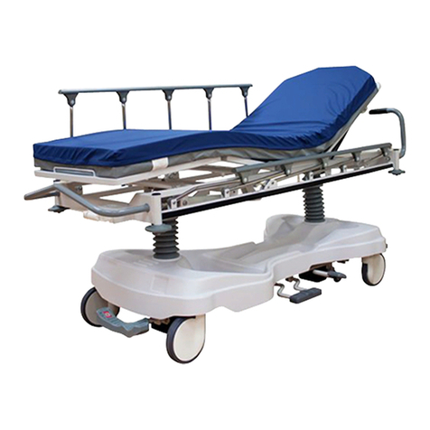
OSKA FLORENCE User manual

oska.uk.com | 0845 381 0600 1
FLORENCE ACUTE BED
USER INSTRUCTIONS
VERSION 1: 13.11.2020

oska.uk.com | 0845 381 0600 3
CHANGING LIVESTM
oska.uk.com
0845 381 0600
FLORENCE ACUTE BED
4
3
2
1
5
6
6
7
14
8
10
11
12
13
9
1. Headboard, removable 2. Grab handles / side mattress guides
3. Control panel (inside) for patient 4. Protega safety side
5. Foot board, removable 6. Locking knobs of the bed extension
(optional) (concealed in picture)
7. Linen holder, extensible, with gallery
rail (optional)
8. Pedal (for braking the bed)
9. Fifth castor (optional feature) 10. Additional hooks
11. Safety side activation 12. Lever for CPR backrest release
13. Wall deflection rollers 14. Control panel (outside) for staff

4 oska.uk.com | 0845 381 0600 oska.uk.com | 0845 381 0600 5
CONTENTS
1 Address, Market information................................................................................ 10
2 Targetgroups,qualicationsandduties............................................................11
2.1 Operator............................................................................................................... 11
2.2 Responsibilities of the operator.................................................................. 11
2.3 Users (medical staff)....................................................................................... 11
2.4 Users (technical staff).................................................................................... 12
2.5 Qualification of users..................................................................................... 12
2.6 Duties of users.................................................................................................. 12
2.7 Patient.................................................................................................................. 13
3 Conventions of this instruction manual.............................................................. 13
3.1 Safety information.......................................................................................... 14
3.2 Icon information............................................................................................... 14
4 Safety information................................................................................................... 15
4.1 Safety information for operating the bed.............................................. 15
4.1.1 Electrical cables and connections.......................................... 15
4.1.2 Operating time of electric drives............................................ 16
4.1.3 Bed adjustment.............................................................................. 16
4.2 Special hazards................................................................................................. 18
4.2.1 Risk of fire........................................................................................ 18
4.2.2 Electromagnetic interference................................................... 18
4.3 Safety information for attachments and additional
equipment.......................................................................................................... 19
4.3.1 Use of additional electro-medical equipment...................................... 19
4.3.1.1 Use of ECG/EEG equipment.................................................... 20
4.3.2 Use of Patient lifts......................................................................... 21
4.4 Safety information for accessories........................................................... 21
4.5 Safety information for disposal.................................................................. 21
5 Product description............................................................................................... 22
5.1 Intended use..................................................................................................... 22
5.2 Use for the intended purpose.................................................................... 22
5.3 Contraindications............................................................................................ 23
5.4 Side effects....................................................................................................... 23
5.5 Product variants.............................................................................................. 23
5.6 Components of the bed............................................................................... 23
5.6.1 Headboards and foot boards................................................... 23
5.6.2 Mattress base................................................................................. 23
5.6.3 Chassis.............................................................................................. 24
5.6.4 Electric drive system................................................................... 24
5.6.5 Control units................................................................................... 24
5.6.5.1 Control panel (inside)............................................... 25
5.6.5.2 Control panel (outside)............................................ 26
5.6.5.3 Control box (optional).............................................. 27
5.6.5.4 Foot pedal (optional)............................................... 30
5.6.6 Safety sides...................................................................................... 31
5.6.7 Linen holder.................................................................................... 32
5.6.7.1 Using the linen holder............................................... 32
5.6.8 Mains cable holder....................................................................... 33
5.6.9 Adapter sleeves for patient lifting pole / infusion
stand (head end).......................................................................... 34
5.6.10 Adapter sleeves for infusion stand (foot end).................. 34
5.6.11 Additional hooks (optional)..................................................... 35
5.6.12 Attachment points for posey belts....................................... 36
5.6.13 Lead-acid battery (optional)................................................... 36
5.7 Technical data.................................................................................................. 38
5.7.1 Type plate........................................................................................ 38
5.7.2 Other labelling on the product............................................... 39
5.7.3 Materials used................................................................................ 39
5.7.4 Dimensions..................................................................................... 40
5.7.5 Weight.............................................................................................. 40
5.7.6 Adjustment ranges....................................................................... 41
5.7.7 Operating noise............................................................................. 41
5.7.8 Ambient conditions...................................................................... 41
5.7.9 Medical device classification.................................................... 42
5.7.10 Electrical data................................................................................ 42
6 Putting into service................................................................................................ 46
6.1 Safety information for putting into service.......................................... 46
6.2 Safety information concerning the place of use................................ 46
6.3 Safety information for electric hospital beds...................................... 47
7 Bed reprocessing / Bed adaptation................................................................... 48
7.1 New occupancy after a change of patient........................................... 48
7.1.1 Information on loading capacity of bed................................................ 48

6 oska.uk.com | 0845 381 0600 oska.uk.com | 0845 381 0600 7
7.1.2 Requirements............................................................................... 48
7.1.2.1 Electric beds............................................................... 49
7.2 Extending / Shortening the mattress base......................................... 49
7.2.1 Pulling out...................................................................................... 49
7.2.2 Slide the extension in................................................................ 50
7.3 Integrated lower leg rest extension (optional).................................... 51
7.3.1 Use for the intended purpose.................................................. 51
7.3.2 Operation......................................................................................... 51
7.3.2.1 Extending...................................................................... 51
7.3.2.2 Retracting...................................................................... 51
7.4 Setting the lower leg rest........................................................................... 52
7.4.1 Mechanically.................................................................................. 52
7.4.1 .1 Raising / Lowering.................................................... 52
7.5 Insert / remove patient lifting pole......................................................... 54
7.6 Attaching the grab handle.......................................................................... 55
7.6.1 Attaching the height................................................................... 56
7.7 Attaching the infusion stand..................................................................... 56
7.8 Using additional hooks................................................................................. 57
7.9 Decommissioning........................................................................................... 58
8 Usage/routine......................................................................................................... 59
8.1 Move and immobilise the bed................................................................... 59
8.1.1 Safety information on moving, braking and
locking the bed............................................................................. 59
8.1.2 Safety information on moving, braking and
locking the bed.............................................................................. 61
8.1.3 Move the bed.................................................................................. 61
8.1.4 Immobilise the bed...................................................................... 62
8.1.5 Move with steering lock............................................................. 52
8.2 Locking / Releasing electric adjustment functions.......................... 63
8.2.1 On the control panel (outside) / on the
control box (optional)................................................................ 64
8.2.2 Lock/unlock the foot pedal..................................................... 65
8.2.3 LED operating mode display................................................... 66
8.2.3.1 LED control panel (inside)..................................... 66
8.2.3.2 LED control panel (outside).................................. 67
8.2.3.3 LED control box (optional).................................... 67
8.3 Setting a sitting position............................................................................ 68
8.3.1 On the control panel (inside/outside)................................. 68
8.3.2 On the control box (optional)................................................. 68
8.4 Setting the backrest...................................................................................... 69
8.4.1 On the control panel (inside and outside)......................... 69
8.4.2 On the control box (optional)................................................. 69
8.5 Setting the bed height................................................................................. 70
8.5.1 On the control panel (inside and outside)......................... 70
8.5.2 On the control box (optional)................................................. 70
8.5.3 On the foot pedal (optional)..................................................... 71
8.6 Setting the thigh rest.................................................................................... 72
8.6.1 On the control panel (inside and outside).......................... 72
8.6.2 On the control box (optional).................................................. 72
8.7 Setting the reverse Trendelenburg position......................................... 73
8.7.1 On the control panel (outside)................................................ 73
8.7.2 On the control box (optional).................................................. 73
8.8 Switching under bed light on / off (optional)..................................... 73
8.9 Using safety sides........................................................................................... 74
8.9.1 Protega safety sides.................................................................... 76
8.9.1.1 Raise.................................................................................................. 76
8.9.1.2 Lower................................................................................................. 76
9 Special functions..................................................................................................... 77
9.1 Setting shock recovery position............................................................... 77
9.1.1 On the control panel (outside) / on the control box
(optional)......................................................................................... 77
9.2 Setting CPR position..................................................................................... 78
9.2.1 On the control panel (outside) / on the control box
(optional)......................................................................................... 78
9.3 Emergency adjustments: Lowering the backrest fast...................... 79
10 Special bed adaptations....................................................................................... 80
10.1 Remove and insert headboard and foot board.................................. 80
10.1.1 Remove............................................................................................ 80
10.1.2 To insert........................................................................................... 80
10.2 Attaching posey belts.................................................................................... 81
11 Cleaning and disinfection..................................................................................... 82
11.1 Safety information on cleaning and disinfection.................................................. 82
11.1.1 Before starting cleaning............................................................ 82
11.1.2 After cleaning................................................................................ 82

8 oska.uk.com | 0845 381 0600 oska.uk.com | 0845 381 0600 9
11.2 Manual cleaning............................................................................................... 83
12 Maintenance............................................................................................................. 84
12.1 Service address................................................................................................ 84
12.2 Safety information on maintenance......................................................... 84
12.2.1 Legal principles.............................................................................. 85
12.3 Recommended lubricants............................................................................ 85
12.4 Recommended special varnishes.............................................................. 85
12.5 Servicing points............................................................................................... 86
12.6 Servicing plan................................................................................................... 88
12.6 .1 Periodic inspection....................................................................... 89
13 Replacement of electrical components............................................................. 90
13.1 Safety information ......................................................................................... 90
13.2 Changing the lead-acid battery.................................................................. 91
13.3 Mains cable replacement.............................................................................. 92
13.4 Connect the earth conductor...................................................................... 92
13.5 Replacing the control panel........................................................................ 94
13.6 Replace the control box............................................................................... 94
13.7 Replace the control unit................................................................................ 95
13.8 Initialising the control.................................................................................... 97
13.8.1 On the control panel (outside)................................................ 97
13.8.2 On the control box (optional).................................................. 98
14 Troubleshooting...................................................................................................... 99
14.1 faults and their rectification........................................................................ 99
14.2 Fault display...................................................................................................... 101
14.3 control panel (outside)................................................................................. 101
14.4 control box (optional).................................................................................. 102
14.5 Acknowledge fault........................................................................................ 103
14.5.1 On the control panel (outside)............................................... 103
14.5.2 On the control box (optional)................................................ 104
15 Disposal.................................................................................................................... 105
15.1 Disposal of the bed....................................................................................... 105
15.2 Disposal of packaging.................................................................................. 105
15.3 Disposal of components............................................................................. 105
15.3.1 Electrical components............................................................... 105
15.3.2 Batteries.......................................................................................... 106
16 Appendix................................................................................................................. 107
16.1 available accessories.................................................................................... 107
16.2 Information on electromagnetic compatibility (EMC)................... 108
16.2.1 EMC information tables........................................................... 109
16.3 Inspection report............................................................................................ 114
16.4 Inspection by the user................................................................................. 120

10 oska.uk.com | 0845 381 0600 oska.uk.com | 0845 381 0600 11
1 ADDRESS, MARKET INFORMATION
Manufacturer:
Stiegelmeyer GmbH & Co. KG
Ackerstrasse 42, 32051 Herford, Germany
Phone: +49 (0) 5221 185-0
Fax: +49 (0) 5221 185-252
Email: info@stiegelmeyer.com
Internet: www.stiegelmeyer.com
To order replacement parts in Germany, and for any customer service requirements
or other questions, please contact our service centre:
OSKA Care Ltd
Edward House, 5 Penner Road, Havant, PO9 1QZ
Phone: +44 (0)845 381 0600
Internet: www.oska.uk.com
No part of this manual may be reproduced without the prior written permission of
the publisher.
All rights reserved.
Subject to technical changes without notice!
This product is not licensed for use on the North American market. This applies
particularly to the United States of America. The distribution and use of this
hospital bed in these markets, including through third parties, is prohibited by the
manufacturer.
2 TARGET GROUPS, QUALIFICATIONS AND DUTIES
2.1 OPERATOR
An operator (e.g. Clinic, hospital, hospital administration) is every natural
and legal person with property rights to the product. The operator is
responsible for the safe operation of this medical product.
2.2 RESPONSIBILITIES OF THE OPERATOR
Please observe your obligations as the operator to ensure that this medical
product is always operated safely and with no risk of danger to patients,
users, or third parties. In other countries the relevant national regulations
concerning the duties of the opera-tor must be followed!
Only permit persons who have been properly instructed to use this bed!
• Using this instruction manual, which is provided with this hospital bed,
ensure that every user is instructed in the safe operation of this bed
before using it for the first time!
• Draw every user’s attention to the possible hazards that can arise if the
hospital bed is im-properly used. This applies in particular to the use of
electrical drives and safety sides!
• Make sure that substitute staff are also sufficiently well instructed in the
safe operation of the hospital bed!
Check to ensure that the safety instructions are adhered to!
If the hospital bed is in long-term use, test the functions and check for any visible
damage after a reasonable period of time (at least once a year)!
If the owner of the hospital bed changes, the instruction manual must be handed
over with the bed.
If any other equipment is attached to the bed (e.g. Compressors for positioning
systems, etc.), ensure that the equipment is securely fastened and is functioning
properly.
If you have any queries or concerns, consult the manufacturer of the equipment or
OSKA.
2.3 USERS (MEDICAL STAFF)
Users (e.g. medical specialists, doctors, nursing staff, carers and
attendants, ...) are persons who, based on their training, experience or
briefing, are qualified to operate the bed on their own authority or to
carry out work on it, or have been instructed in how to handle this bed.
Furthermore, they can recognise and avoid potential dangers and assess
the clinical condition of the patient.

12 oska.uk.com | 0845 381 0600 oska.uk.com | 0845 381 0600 13
CAUTION!
Risk of injury
If any damage or malfunction is suspected, take the bed out of
service.
- Unplug the bed from the mains supply immediately.
- Indicate clearly that the hospital bed is “OUT OF ORDER”.
- Report this immediately to the operator responsible.
2.4 USERS (TECHNICAL STAFF)
Users with a technical background (e.g. company technicians, service
engineers or persons who are capable of carrying out special technical
work on the hospital bed due to their training or briefing through the
operator).
2.5 QUALIFICATION OF USERS
The operator must only appoint users with the following three minimum
qualifications to operate the hospital bed:
• Medical training
• Experience in dealing with patients and hospital beds
• Instruction in handling this hospital bed through the operator
The operator must only appoint people with the following minimum
qualification to maintain the hospital bed:
• Technical experience of setting and maintaining hospital beds
• Have read and understood the special operation and maintenance
instructions for this bed contained in this instruction manual
2.6 DUTIES OF USERS
Ensure that the operator instructs you in the safe operation of this bed.
Please also follow the corresponding instructions in the instruction manual
for accessories attached to the bed.
Pay special attention here to the safe routing of all loose connector cables,
tubing, etc.
Ensure that no obstacles such as bedside cabinets, supply rails or chairs
could impede adjustments to the bed.
If other equipment (e.g. compressors for positioning systems, etc.) is
attached, ensure that all items of equipment are securely fixed and
function properly.
If you have any queries or concerns, consult the manufacturer of the
equipment or OSKA.
2.7 PATIENT
A patient is defined as a person who is in need of care, ill, infirm or
disabled, and occupies this bed.
It is a requirement that the operator or user instructs each new patient in
the bed functions that are important for him/her.

14 oska.uk.com | 0845 381 0600 oska.uk.com | 0845 381 0600 15
3 CONVENTIONS OF THIS INSTRUCTION MANUAL
3.1 SAFETY INFORMATION
In this instruction manual, safety information is displayed in the following
way:
WARNING!
WARNING indicates a potentially hazardous situation that, if not
avoided, could result in death or serious injury.
CAUTION!
CAUTION indicates a potentially hazardous situation that, if not
avoided, could result in minor or moderate injury.
IMPORTANT!
NOTICE indicates a harmful situation that could result in damage to the
product or something around it.
3.2 ICON INFORMATION
General information and cross-references will be displayed in the following
way:
General information, tips and helpful courses of action.
Cross-reference or active link: The double arrow separates the
chapter title or chapter number from the page numbers. Example:
See Safety Information page 15.
4 SAFETY INFORMATION
4.1 SAFETY INFORMATION FOR OPERATING THE BED
This hospital bed is not suitable for patients under 146cm in height or for
small children.
This hospital bed may only be operated by persons who have received
instruction from the opera-tor in its safe operation.
Electrical adjustments are only possible when the hospital bed is properly
connected to the mains supply (exception: emergency battery operation).
If the owner of the hospital bed changes, the instruction manual must be
handed over with the bed.
4.1.1 ELECTRICAL CABLES AND CONNECTIONS
WARNING!
Danger of electric shock
Damaged mains cables can cause fatal electric shocks. Take the
following measures to prevent hazards due to electric shock and
malfunctions.
• If a damaged mains cable continues to be used, this can lead to
electric shock, fire and other hazards as well as malfunctions. A
damaged mains cable must be replaced immediately!
• Connect the bed only to a properly earthed mains electrical
socket.
• Route the mains cable in such a way that it cannot be pulled,
driven over or damaged by moving parts, or in any other way,
when the bed is operated. Before moving the bed, al-ways make
sure that you have unplugged it from the mains supply.
• Before moving the bed, always make sure that you have
unplugged it from the mains socket.
• Hang the mains cable in the mains cable holder provided on the
headboard to ensure that it will not fall off or trail on the floor.
• At weekly intervals when the bed is being used, carry out a visual
inspection of the mains cable to check for damage (scuffing,
exposed wires, kinks, pressure points, etc.). A check should also
be performed whenever the cable has been subjected to any
mechanical load, e.g. has been driven over by the bed itself or
by an equipment trolley, or whenever the cable has been bent,
stretched or violently pulled, e.g. due to the bed rolling away
while it is still plugged into the mains socket, and before

16 oska.uk.com | 0845 381 0600 oska.uk.com | 0845 381 0600 17
• Plugging the cable back into the mains socket whenever the bed
has been moved or relocated.
• Check the strain relief of the power mains cable regularly to
ensure that it is securely fixed.
• Do not place multiple socket bars under the bed. This could
cause electrical hazards due to damaged mains cables or
penetrating fluids.
• Do not continue to use the bed if you suspect that the mains
cable could be damaged.
4.1.2 OPERATING TIME OF ELECTRIC DRIVES
Continuous operation must not exceed two minutes. After this time, a
rest period of at least 18 minutes must be observed.
If the electric drive is operated for a much longer period, e.g. due to
the patient continually “playing” with the control panel, the electronic
thermal protection device integrated in the control unit will deactivate
the thermal protection device temporarily.
In this extremely rare case, the control unit will be available for use
again after cooling down for approximately 20 minutes.
4.1.3 BED ADJUSTMENT
CAUTION!
Risk of crushing
Failure to heed this may result in physical injuries!
• When making any adjustments, always ensure that there are no
limbs belonging to patients, users, other persons, and especially
playing children, that could be trapped underneath the rests or
the mattress base.
IMPORTANT!
Material damage
Failure to heed this may result in damage to the hospital bed and/or lifting
frame and this could have an adverse effect on the loading capacity of the
hospital bed or the adjusting functions.
Ensure that
• No obstacles such as bedside cabinets, supply rails, other equipment,
chairs or wall protection rails are in the way,
• There are no objects lying on the chassis,
• People are not sitting on slightly raised sections of the backrest and leg
rests.
If the load is too high, an electronic overload switch is activated and the drive
system is automatically switched off. After a short movement in the opposite
direction and removal of the overload source, the drive system will continue to
move in the intended direction.

18 oska.uk.com | 0845 381 0600 oska.uk.com | 0845 381 0600 19
4.2 SPECIAL HAZARDS
4.2.1 RISK OF FIRE
WARNING!
Risk of fire
Various external factors can result in a fire. To prevent a fire, take
the following precautionary measures.
• Use only flame-retardant mattresses and bedding if possible.
• Inform patients that smoking is not allowed in bed.
• Only use additional equipment (e.g. electric blankets) and
other electrical devices (e.g. lamps, radios) that are in perfect
working order!
• Ensure that this equipment is used only for the purpose
intended.
• Ensure that this equipment is not inadvertently placed on or
under the bedding (danger of overheating)!
• Avoid using extension cables or multiple socket bars under the
bed (risk of fire due to penetrating fluids).
• Do not place any flammable materials (e.g. bedding) or any
solid, hard objects underneath the mattress base (danger
of heat congestion/electrical hazards when in contact with
electrical components installed there, especially in the area of
the power supply/battery under the backrest)
4.2.2 ELECTROMAGNETIC INTERFERENCE
As electro-medical equipment, this hospital bed is subject to special safety
measures with respect to electromagnetic compatibility (EMC). For this
reason, observe the following instructions when installing and operating
the hospital bed.
Portable and mobile high-frequency communication devices (e.g. cordless
telephones, mobile telephones, baby monitors, WLAN, WIFI, wireless
equipment, etc.) can influence the operation of electro-medical equipment.
These influences have been minimised by means of the robust, interference
resistant design of the electrical adjustment features of this bed.
This hospital bed must not be used in combination with high frequency
surgical equipment.
As with every electrical device, even if all the specified EMC limiting values
are observed during operation, disruptions from and to other closely
situated high-frequency communication devices cannot be completely
ruled out (e.g. ‘crackling’ on a radio). In such rare cases, increase the
distance between the devices or align them differently, and make sure
that they do not use the same electrical outlet, or switch the disruptive/
disrupted device off temporarily. Explain the necessary precautions to the
patient as well.
For further technical details see page 108.
4.3 SAFETY INFORMATION FOR ATTACHMENTS AND ADDITIONAL
EQUIPMENT
Efficient and safe operation combined with maximum protection of
patients can only be guaranteed if original OSKA accessories are used that
are designed for the relevant model of bed! Make sure that by attaching
accessories, crush or shearing zones for the patient are not created when
the bed sections are adjusted. If this cannot be ensured, you must lock
those particular adjustment controls! (for more information, see page 63.
4.3.1 USE OF ADDITIONAL ELECTRO-MEDICAL EQUIPMENT
When additional mains-operated electrical (electro-medical) equipment
such as infusion pumps, data processing devices, ECG/EEG devices, etc.,
is used in combination with this electrically adjustable bed, the entire
arrangement constitutes an “electro-medical system”.
When using electro-medical equipment, precautions must be taken to
comply with electromagnetic compatibility (EMC) requirements and
allowable leakage current limits. The installation and commissioning of
electro-medical devices must be carried out in accordance with EMC
recommendations described in the accompanying documentation. If
necessary, the bed (using the connection pin at the head end of the bed),
and also the additional equipment associated with the bed, should be
connected to the hospital’s potential equalisation (PE) system.
When the bed is connected to the mains electricity supply, it must
always be connected to the hospital’s potential equalisation system when
intravascular and intracardiac applications are involved. The potential
equalisation of the bed applies to the mattress base frame. Additional
assemblies and accessories (such as headboards and foot boards, safety
sides, patient lifting poles, infusion stands) are excluded from these
requirements.

20 oska.uk.com | 0845 381 0600 oska.uk.com | 0845 381 0600 21
Fig. 1: Connection pin and potential equalisation symbol
In addition, observe the information given in:
• Chapter Electromagnetic interference (page 18) and Chapter Safety information
concerning the place of use (page 46)
• All the information given in the instruction manuals of the additional devices as
well as the requirements stipulated in the relevant standard EN 60601-1.
4.3.1.1 USE OF ECG/EEG EQUIPMENT
It is not normally a problem to use ECG/EEG patient monitoring
equipment together with this hospital bed.
Should the bed’s electrical equipment, contrary to expectation, have a
marginal effect on the measurements, the ECG electrode conductors
should be placed as parallel as possible to the patient’s arms and legs. The
bed should then be connected to the hospital’s potential equalisation (PE)
system using the connection pin at the head end of the bed.
Many of these devices also feature a 50Hz / 60Hz line filter which can be
turned on if necessary. If this measure is not sufficient, unplug the bed
from the mains supply.
This effectively avoids any possible malfunctions.
4.3.2 USE OF PATIENT LIFTS
IMPORTANT!
Material damage
If the mattress base is at its lowest height, the use of patient lifts may damage
cables and drives.
• Do not wheel the patient lift under the hospital bed when this is at its
lowest level.
• Raise the mattress base until it is about 10cm higher before wheeling the
patient lift under the hospital bed.
4.4 SAFETY INFORMATION FOR ACCESSORIES
CAUTION!
Incorrect accessories
Incorrect accessories and unsuitable spare parts can result in injury
and material damage to the bed and its surroundings. Only use
original OSKA accessories matching the model of the bed to ensure
correct and safe function and maximum patient safety!
• Only use original accessories by OSKA.
4.5 SAFETY INFORMATION FOR DISPOSAL
WARNING!
Risk of infection
Failure to heed this may result in adverse effects for human health!
• The operator must ensure that all components of the bed that
are to be disposed of are not infectious or contaminated.
CAUTION!
Environmental risk
Failure to heed this may result in environmental damage!
• Do not dispose of batteries with domestic waste.
• They can be returned to OSKA or disposed of at local waste
collection points in the same way as car batteries.
• Outwardly undamaged, discharged battery sets can also be
returned to OSKA.

22 oska.uk.com | 0845 381 0600 oska.uk.com | 0845 381 0600 23
5 PRODUCT DESCRIPTION
This bed fulfils all the requirements of the 93/42/EEC and, from May 2021,
the Medical Device Regulation (EU) 2017/745 (MDR). It is classified as a
Class l active medical device in accordance with MDR.
5.1 INTENDED USE
• This bed is designed for positioning and transporting patients, as an
aid to diagnosing, monitoring, treating, and alleviating illnesses or
compensating for injuries or disabilities. For detailed instructions for
use, see page 59
• This bed is suitable for accommodating adult patients only (= persons
whose height is at least 146 cm).
• The bed itself is not life sustaining or life supporting.
• The bed has no medical indication.
5.2 USE FOR THE INTENDED PURPOSE
• The bed may only be used in hospitals and comparable medical
facilities with qualified personnel within closed rooms.
• Qualified personnel must be skilled in handling the beds and be
thoroughly conversant with the instruction manual.
• If the owner of the hospital bed changes, the instruction manual must
be handed over with the bed.
• The bed with its stable, smooth-running castors is designed for being
moved within the room as well as frequently in corridors and across
thresholds with a height of up to 2 cm.
• The safe working load is 225 kg (patient + accessories).
• This bed is suitable for repeated use.
• This bed must not be used in explosive environments caused, for
example, by cleaning agents or anaesthetics.
• This bed must not be used in combination with high frequency
surgical equipment.
• Before using the safety sides, assess and take into consideration the
clinical condition and particular physical build of the patient. Observe
the special safety information in Chapter 9.9 » 66.
This bed may only be used under the operating conditions described in this
instruction manual. Its use for any other type of application is deemed to be
contrary to the intended purpose.
5.3 CONTRAINDICATIONS
This bed is only suitable for patients who do not fall
below the following minimum body size/weight:
• Height: 146 cm,
• Weight: 40 kg
• Body mass index1 ‘BMI’: 17.
• Owing to the smaller limbs of patients with lower body
measurements/weight, there is an increased risk of entrapment
between the open spaces of the safety sides when safety side systems
are used.
5.4 SIDE EFFECTS
Unless suitable measures are taken, long-stay patients may develop
decubitus.
5.5 PRODUCT VARIANTS
The OSKA Florence Acute Bed – select version is available with the
following mattress base heights. The mattress base height of the hospital
bed can differ depending upon the type of castors used.
- Mattress base size (W x L) in cm: 87x200
- Mattress base height adjustment range in cm: 36 - 81.5 or 38.5 - 84
(depending on type of castors)
5.6 COMPONENTS OF THE BED
5.6.1 HEADBOARDS AND FOOT BOARDS
The standard version of the bed comes with removable head and foot
boards to provide better access to the patient in certain cases (such as for
taking X-rays).
5.6.2 MATTRESS BASE
The mattress base is divided into a backrest, a seat section, a thigh rest
and a lower leg rest. The mattress base height can be adjusted when
the mattress base is horizontal, and can be tilted into a Trendelenburg
or reverse-Trendelenburg position. The backrest and thigh rest can be
adjusted separately. The components for the electric drive system are
accommodated under the mattress base. A bed extension is contained
in the standard version. For details concerning use, refer to Extending /
Shortening the mattress base page 49.
Sticker on chassis of bed

24 oska.uk.com | 0845 381 0600 oska.uk.com | 0845 381 0600 25
5.6.3 CHASSIS
The chassis is located underneath the mattress base. The bed has four
castors that can be centrally locked with a brake pedal. One of the castors
is equipped with a steering lock which enables the bed to be moved in a
straight line.
Fifth castor (optional)
The chassis can be fitted with an optional fifth castor which is installed
at the centre of the chassis. In this case, the fifth castor takes over the
function of the steering lock.
5.6.4 ELECTRIC DRIVE SYSTEM
The electrical drive system for this bed consists of the following
components:
• Four drives for the backrest, the thigh rest and the mattress base
height.
• Central control unit under the mattress base (head end). The control
unit there uses a transformer to generate a 24-volt protective low
voltage which is non-hazardous for patients and users. The drives and
the control panel (inside and outside) are connected to the control
unit. These components operate on the 24-volt protective low voltage
generated and have dust and water protected plug connections.
• Optional equipment: Lead-acid batteries for mains-independent
emergency operation, control box, under bed light, foot pedal.
5.6.5 CONTROL UNITS
The hospital bed provides the following control units for adjusting the bed
and positioning components. The bed is equipped with a control panel
(inside) and a control panel (outside) as standard supply. The following
table shows the standard features and the optional equipment:
Designation of
components
Component variants Standard features (x)
Options (o)
Control panel (inside) +
control panel (outside)
x
Foot pedal o
Control box o
Lead-acid battery o
Under bed light o
The control box and foot pedal are only for use by medical and technical
personnel.
5.6.5.1 CONTROL PANEL (INSIDE)
The control panel is integrated into the Protega safety side at the head
end and is designed for use by the patient. Patients can adjust approved
bed adjustments from the comfort of their lying position.
1 2 6
3
7
8
4
5
Fig. 2: (Inside) control panel control level
1. Backrest adjustment 2. Mattress base height adjustment
function
3. Sitting position adjustment function 4. Thigh rest adjustment
5. LED 6. UP button
7. Under bed light button 8. DOWN button

26 oska.uk.com | 0845 381 0600 oska.uk.com | 0845 381 0600 27
Fig. 4: Position of control box
5.6.5.2 CONTROL PANEL (OUTSIDE)
The control panel is attached on the outside of the head-end Protega
safety side and so is only accessible for medical personnel. Medical staff
can use the panel to adjust the bed and to lock or unlock adjustment
functions for the integrated (inside) control panel, depending on the
clinical condition of the patient.
1 8
9
7
6
10
2
5
12
3 4 11
1. Backrest adjustment 2. Sitting position adjustment function
3. Mattress base height adjustment
function
4. LED
5. Under bed light button 6. Thigh rest adjustment
7. Reverse-Trendelenburg position
adjustment
8. UP button
9. DOWN button 10. Lock/unlock button
11. CPR button (resuscitation position) 12. Shock position (Trendelenburg
position) adjustment function
5.6.5.3 CONTROL BOX (OPTIONAL)
The control box is an optional piece of equipment. The control box is used
to carry out all motorised adjustments and to lock the functions of the
control panel (inside) for the patient.
When the bed is connected to the mains supply, the battery charge display
lights up orange.
The control box is located in the linen holder. The control box can be
removed from the linen holder and can be attached to the foot board
handrail.
Button/Display Explanation
Sitting position button
Normal position button
Backrest adjustment
Thigh rest adjustment
Height adjustment of mattress base

28 oska.uk.com | 0845 381 0600 oska.uk.com | 0845 381 0600 29
Button/Display Explanation
Reverse-Trendelenburg position adjustment
UP button
DOWN button
CPR button (resuscitation position)
Shock position button (Trendelenburg position)
Lock/unlock button:
For locking and releasing each of the functions
Press this button along with the CPR button/shock position
button to activate the respective function
Under bed light button
Battery charge indicator
USING THE CONTROL BOX
Similar to illustration. Identical procedure.
1. Pull the linen holder out from under
the mattress base. The linen holder is
located under the foot board.
2. Take the control box out of the linen
holder and hang it onto the top rail of
the foot board. This makes it easier
and more ergonomic to use.
3. Place the control box back in the
linen holder when it is no longer
needed and slide the linen holder
back under the foot board. Ensure
that cables are routed correctly (do
not pinch or trap the cables).

30 oska.uk.com | 0845 381 0600 oska.uk.com | 0845 381 0600 31
5.6.5.4 FOOT PEDAL (OPTIONAL)
The foot pedal is an optional piece of equipment. The foot pedal is
attached to the transverse beam on the bed chassis. Users can raise or
lower the bed by pressing the corresponding part of the toggle switch.
The foot pedal is fitted with a protective pedal guard to prevent accidental
use.
Fig. 5: Position of foot pedal
The different parts of the toggle switch on the foot pedal are used to operate the
following functions:
Button/Display Explanation
+Height adjustment range: Raise mattress base
-Height adjustment range: Lower mattress base
Foot pedals are always locked for safety reasons. Refer to page 71 for
instructions on how to unlock the foot pedal.
5.6.6 SAFETY SIDES
The bed is equipped with Protega safety sides to protect the patient from
accidentally falling out of bed. Medical staff can lower safety sides by
hand.
Fig. 6: Protega safety sides

32 oska.uk.com | 0845 381 0600 oska.uk.com | 0845 381 0600 33
5.6.7 LINEN HOLDER
The foot end of the bed is fitted with a linen holder that can be drawn out
to provide a hygienic surface to put bedding on. Depending on the model
of bed, the control box is located in the linen holder.
Fig. 7: Linen Holder
5.6.7.1 USING THE LINEN HOLDER
IMPORTANT!
Material damage
• Failure to heed the maximum loading capacity of the linen holder (15 kg)
will result in material damage.
• Do not sit/lean on the linen holder!
• Hard objects can unintentionally press the keys of (optional) electrical
control units inside the linen holder and lead to malfunctions.
• When removing and re-inserting the control box, pay attention to the cable
routing. Ensure that the cable cannot be caught, stretched, crushed or
otherwise damaged.
CAUTION!
Risk of injury
Failure to heed this may result in the pulled-out linen holder
becoming a tripping hazard.
• Always slide the linen holder back into place immediately after
use.
1. Pull the linen holder out from under
the mattress base with a slight jerk.
2. A gallery rail is attached to the linen
holder. If necessary, raise the gallery
rail to an up-right position. This helps
to hold the bed-ding in place.
5.6.8 MAINS CABLE HOLDER
The mains cable holder (1) is attached to the mains cable.
1
Fig. 8: Mains cable holder attached to the headboard
Hook the mains cable holder
(1) onto the headboard or
foot board before moving
the bed to pre-vent the
mains cable from being
driven over, crushed or torn
off.

34 oska.uk.com | 0845 381 0600 oska.uk.com | 0845 381 0600 35
5.6.9 ADAPTER SLEEVES FOR PATIENT LIFTING POLE / INFUSION STAND
(HEAD END)
On the inside of the headboard, there is an adapter sleeve on each side of
the bed for attaching a patient lifting pole or infusion stand.
Reducing adapters (A) (either round or oval, as the customer wishes) are
inserted in the sleeves before leaving the factory, to hold a round or oval
patient lifting pole.
A second plastic reducing adapter is inserted in one of the sleeves before
leaving the factory (B) This can be used if an infusion stand is inserted.
A grab handle is normally attached to the patient lifting pole (see Available
accessories page 107).
1
A
B
Fig. 9: Position of patient lifting pole adapter sleeves
5.6.10 ADAPTER SLEEVES FOR INFUSION STAND (FOOT END)
On the inside of the foot board, there is an adapter sleeve on each side of
the bed for attaching a patient lifting pole or infusion stand.
Fig. 10: Position of infusion stand adapter sleeves (at foot end)
5.6.11 ADDITIONAL HOOKS (OPTIONAL)
The bed can optionally be fitted on each long side with additional hooks
(B) . Additional hooks can be used to hang accessories such as urine bags.
IMPORTANT!
Material damage
Failure to heed this note may result in material damage.
• When the bed is moved, ensure that accessories hanging in the universal
holders are not knocked against and damaged as a result.
BB
Additional hooks must not be subjected to a weight of more than 2 kg.
Fig. 11: Additional hooks

36 oska.uk.com | 0845 381 0600 oska.uk.com | 0845 381 0600 37
5.6.12 ATTACHMENT POINTS FOR POSEY BELTS
The plastic mattress base can optionally be fitted with slots for posey
belts. The arrows show slots in the plastic mattress base through which
restraint system belts can be threaded.
WARNING!
Risk of injury
Failure to heed this may result in patient injury.
• Lock all adjustment functions on the control panel (inside) when
using posey belts.
Fig. 12: Slots for posey belts
5.6.13 LEAD-ACID BATTERY (OPTIONAL)
As an option, a conventional high-capacity lead-acid battery can be used
for temporary emergency operation of the electrical drive system. This
guarantees that all motorised adjustments can be carried out even during
a power cut.
Emergency operation
When the bed is occupied by a patient of normal weight (approx. 80 kg),
up to 8 full UP/DOWN adjustments can be made if the battery is new and
fully charged.
IMPORTANT!
Material damage
Failure to heed this note will result in damage to the lead-acid battery.
If the battery charge is low, all adjustment functions are locked in order to
prevent the battery from discharging its entire charge.
In this case, take the following action to optimise the battery life:
• Connect the bed to the mains power supply as soon as possible to
recharge the battery.
• Avoid attempting repeated motorised adjustments that would discharge
the battery even more.
Recharging/Battery charge indicator The lead-acid batteries are fully charged when
the bed has been connected to the mains supply for at least 8-10 hours.
It is impossible to overcharge the lead-acid batteries.
During the charging process, the bed can be adjusted using the control panel
(outside/inside) or the control box (optional).
The lead-acid batteries have a limited service life. In normal use, this service life is
up to five years. Batteries need to be replaced when operation cycles become very
short. For safety reasons, at least one more height adjustment (up + down) should
always be possible under normal load. Otherwise, the lead-acid batteries must be
replaced.
In this case, contact OSKA’s service centre. We will replace the rechargeable lead-
acid batteries and dispose of the old batteries properly.
When the bed is connected to the mains supply, an orange LED on the control box
indicates that the battery is charging.
LED on the control box Explanation
Orange LED lights up: Battery charging
Does not light up: Battery fully charged
Under emergency conditions, if the battery capacity is depleted, a signal
tone will sound during adjustments.

38 oska.uk.com | 0845 381 0600 oska.uk.com | 0845 381 0600 39
5.7 TECHNICAL DATA
5.7.1 TYPE PLATE
The type plate is at the head end of the mattress base (inner side) and
contains the following information:
Model Name of product Item number
Order number Date of manufacture
(week/year)
Only for use in enclosed
spaces. Do not use
outdoors!
Device with type
B applied part in
accordance with
EN 60601-1 (special
protection against
electric shock)
Ser. no Serial number (e.g. 3/10) Medical devices labels
Product is in accordance
with European WEEE
Directive 2012/19/EU
(avoidance of waste
electrical and electronic
equipment) Do not
dispose of electrical parts
in house-hold waste
IP X4
Protection of electrical
equipment from water
splashing from any
direction
PID bar code
The additional PID bar code on the bed
includes a number that clearly identifies
each particular bed.
5.7.2 OTHER LABELLING ON THE PRODUCT
Caution! Follow the operating instructions
Only use mattresses that
are approved by the
manufacturer.
Max. patient weight
Safe working load =
max. patient weight +
accessories
Total mass of the bed
= dead weight + safe
working load
Lock the hand control if
the patient could be at
risk due to inadvertent
motorised adjustments
Minimum patient
dimensions/weight:
Height: 146 cm,
Weight: 40 kg;
Body mass index ‘BMI’:
17
5.7.3 MATERIALS USED
The bed is made predominantly of steel sections coated with a polyester
powder finish or a zinc or chromium metal finish.
The mattress base is made of high-quality, PVC-free plastics.
The chassis is made of steel sections.
Rondo and Stelo head and foot board panels consist of HPL moulded
laminate boards and Inter-continental head and foot board panels consist
of high-quality PP plastic.
All surfaces that can be touched during normal use have been tested for
bio-compatibility and are harmless to humans when in contact with the
skin.
Table of contents
Other OSKA Medical Equipment manuals
Popular Medical Equipment manuals by other brands
Brainlab
Brainlab Universal quick start guide
I-Tech
I-Tech Power Q-6000 Plus user manual

Aspen Medical Products
Aspen Medical Products ELITE EXTENSION PANEL quick start guide
ResMed
ResMed ApneaLink Patient instructions
Mizuho
Mizuho Lateral Cassette Holder Instructions for use
Richmar
Richmar InTENSity 10 Quick reference guide
Blatchford
Blatchford Silcare Breathe Walk Cushion Liner user guide
medi
medi Collamed long Instructions for use

Dräger Medical
Dräger Medical Babytherm 8004 operating instructions
IBP
IBP ELECTRICAL NERVE STIMULATOR manual

ResMed
ResMed Swift FX user guide
LPG
LPG CELLU M6 Alliance Lab Medical Operator's manual
