Sase PDG 8000 User manual

Revision: 1
Created: 2/14/2014
Remote Control - PDG 8000 Manual
SASE Company, Inc.
Phone: 800.522.2606 Fax: 877.762.0748
www.SASECompany.com


Table of Contents
Safety Instructions ................................................... 1-2
Introduction ................................................... 3
Transportation ................................................... 3
Storage ................................................... 3
Setup and Operation ................................................... 4-6
Changing of Diamonds ................................................... 7
Determining Diamond Selection....................................... 8-9
Plastics & Water System.................................................. 10-11
Testing Stage ................................................... 12-13
Motor On Drum ................................................... 14-15
Frame without Drum ................................................... 16-17
Handle Assembly ................................................... 18-19
Basic Frame ................................................... 20-21
Step View ................................................... 22-23
Complete Drum ................................................... 24-25
Bottom Drum Assembly Level I........................................ 26-27
Bottom Drum Assembly Level II....................................... 28-29
Bottom Drum Assembly Level III...................................... 30-31
Top Plate Assembly ................................................... 32-33
Drum Sheave Assembly................................................... 34-35
Intermediate Sheave Assembly........................................ 36-37
PTO Tensioner Assembly................................................. 38-39
Top Belt Idler Assembly................................................... 40-41
Top Tensioner Assembly.................................................. 42-43
Belt Tightener ................................................... 44-45
Main Belt Idler ................................................... 46-47
Main Belt Spindle ................................................... 48-49
Planetary Assembly ................................................... 50-51
PTO Assembly ................................................... 52-53
Flex Head ................................................... 54-55
Tooling ................................................... 56-57
Inverter ................................................... 58-59
Operator Control Panel................................................... 60-61
Belt Paths ................................................... 62
Technical Specifications................................................... 63

List of Fault or Alarm Indicators....................................... 64-67
Certificate of Declaration and Conformity.......................... 68

Safety Instructions
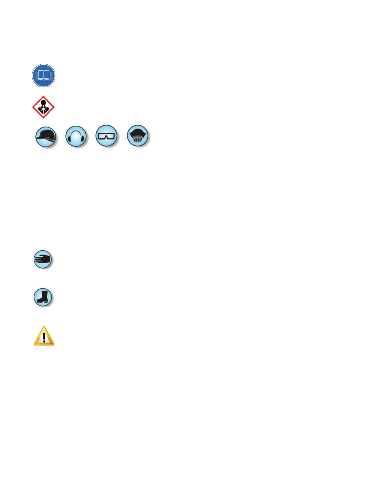
Please read the operator’s manual carefully and make sure you
understand the instructions before using the machine.
WARNING! Dust forms when grinding which can cause injuries if
inhaled. Use an approved breathing mask. Always provide for
good ventilation while machine is in use.
Always wear:
Approved protective helmet.
Approved hearing protection.
Protective goggles or a visor.
Dust Mask
Dust forms when grinding, which can cause injuries if inhaled.
Always wear approved protective gloves.
Always wear sturdy non-slip boots with steel toe-caps.
WARNING
Under no circumstances may the machine be started without ob-
serving the safety instructions.
Should the user fail to comply with these, SASE Company Inc or its
representatives are free from all liability both directly and indirectly.
Read through these operating instructions and make sure that you
understand the contents before starting to use the machine.
Should you, after reading these safety instructions, still feel uncer-
tain about the safety risks involved you must not use the machine,
please contact your SASE representative for more information.
Only qualified personnel should be allowed to operate machinery.
Never use a machine that is faulty. Carry out the checks, mainte-
nance and service instructions described in this manual. All repairs
not covered in this manual must be performed by a repairer nomi-
nated by either the manufacturer or distributor.
Always wear personal safety equipment such as sturdy non-slip
boots, ear protection, dust mask and approved eye protection.
The machine should not be used in areas where potential for fire or
explosions exist.
Machinery should only be started when grinding heads are resting
on the ground.
The machine should not be started without the rubber dust skirt
attached. It is essential a good seal between floor and machine be
established for safety, especially when operating in dry grinding
applications.
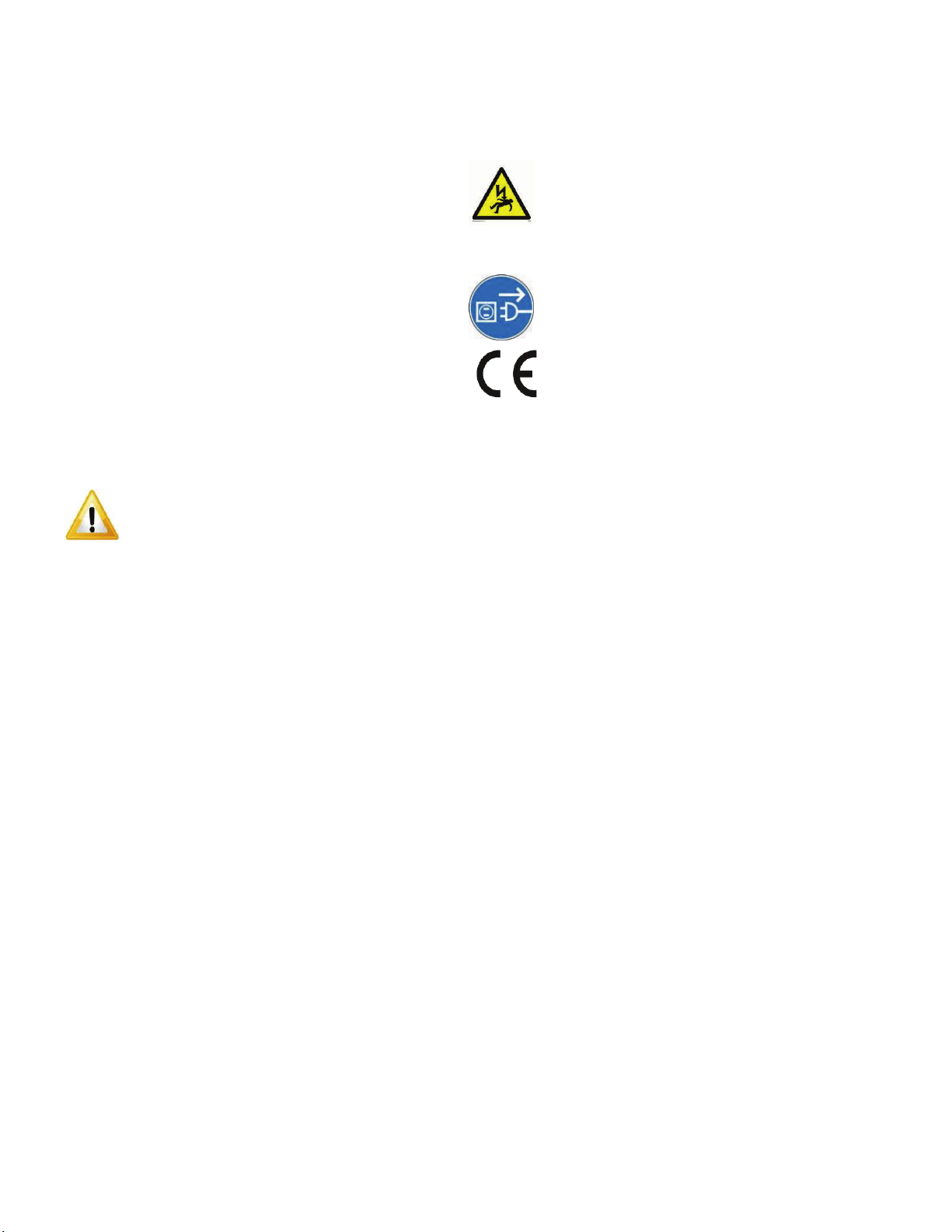
When changing the grinding discs ensure power supply to the unit
is OFF by engaging the Emergency Stop button and the power-plug
disconnected.
The machine should not be lifted by handles, motor, chassis or
other parts. Transportation of the machine is best done on a pallet /
skid to which the machine must be firmly secured.
Extreme caution must be used when moving machinery by hand on
an inclined plane. Even the slightest slope can cause forces/
momentum making the machinery impossible to brake manually.
Never use the machine if you are tired, if you have consumed any
alcohol, or if you are taking medication that could affect your vision,
your judgment or your coordination.
Never use a machine that has been modified in any way from its
original specification.
Be on your guard for electrical shocks. Avoid having body contact
with lightning conductors/metal in the ground.
Never drag the machine by means of the cord and never pull out
the plug by pulling the cord. Keep all cords and extension cords
away from water, oil and sharp edges.

Safety Instructions
Check that the cord and extension cord are intact and in good condi-
tion. Never use the machine if the cord is damaged, hand it in to an
authorized service workshop for repair.
Does not use a rolled up extension cord.
Electrical cords must not exceed 200ft in length.
The machine should be connected to an earthed outlet socket.
Check that the mains voltage corresponds with that stated on the
rating plate on the machine.
Ensure the cord is behind you when you start to use the machine so
that the cord will not be damaged.
WARNING
A
t no time should lifting of machinery be attempted without
mechanical means such as a hoist or a forklift.
WARNING HIGH VOLTAGE!
Inspection and/or maintenance should be carried out
with the motor switched off and the plug discon-
nected.
This product is in accordance with applicable
EU directives

Introduction
The SASE PDG 8000 planetary diamond grinders are designed for wet or
dry grinding of marble, terrazzo, granite and concrete. Their applications
range from rough grinding through to a polished finish.
It is extremely important all users be familiar with the contents of this
manual before commencing operation of either machine. Failure to do so
may result in damage to machinery or expose operator to unnecessary
dangers.
IMPORTANT!
Only staff that has received the necessary training, both practically and
theoretically concerning their usage should operate the machinery.
Transportation
The machine comes equipped with an electronic system called a variable
speed drive or a frequency converter. The drive enables the variable
speed and direction component of the motor.
The drive is located in the steel cabinet mounted on the machine chassis.
As with all electronic equipment, the drives are sensitive to excessive
vibration, rough treatment and high levels of dust. Much care and atten-
tion has been given by SASE to ensure maximal protection is given to the
drive. Note the shock absorbing mounting system used to mount the
steel cabinet on the machine chassis/frame.
When transporting, it is important to ensure the machinery is properly
secured at all times to eliminate “bouncing” of the variable speed drive.
Ensure the chassis or frame section of the machine is secured down at
all times when in transit.
The machine should always be transported under cover limiting the ex-
posed to natural elements – in particular rain and snow.
WARNING
The machine should not be lifted by handle, motor, chassis or other
parts. Transportation of the machine is best done on a pallet/skid to
which the machine must be firmly secured.
Do not attempt to slide the tines/forks from a fork lift under grinding
heads unless on a pallet/skid.
Failure to do so can cause irreparable damage to grinding heads of
machine and internal parts.
IMPORTANT!
It is recommended that machinery be transported with a set
of diamonds attached at all times to ensure protection of
locking mechanism for diamond plates.
Storage
The machine should always be stored in a dry place when not in use.

Planetary head and grinding heads are set to turn in opposite directions
of each other. (Planetary head turns clockwise while grinding heads
turn counter clockwise or planetary heads turn counter clockwise while the
grinding heads turn clockwise.)

to start machine

Setup and Operation
Planetary rotation direction
The correlation between FWD/REV & Clockwise/Counter clockwise rota-
tion can be said as follows if looking at the grinding discs from under-
neath the machine:
REV-Clockwise.
FWD-Reverse.
As mentioned earlier, when the machine is in operation it will pull to one
side. The direction of pull is determined by the planetary head direction
of rotation. The head of the machine will pull to the right (and therefore,
will be felt on the right hip of the operator) when the planetary head is
set in the REVERSE direction.
This sideways pull can be very useful when grinding, particularly along a
wall. Set the machine so that it pulls towards the wall, and then control
the machine so it can just touch the wall. This will ensure a grind close
to the wall or object.
Direction is also a matter of personal preference, however to improve the
cutting efficiency of diamonds, change directions on a regular basis. This
will work both sides of the diamond crystals, keeping the abrasives as
sharp as possible by creating maximal exposure of the diamond crystal.
Once both a speed and direction have been nominated, switch on dust
extraction or vacuum device.
IMPORTANT!
It is highly recommended to use a SASE BULL 1250 Industrial
Vacuum system for complete dust control.

Changing of Diamonds
Different applications often require different selections of diamond
tooling. There will be many occasions when the grinding discs need
to be changed.
Following is a guide for this procedure.
Preparation
Press the Stop button and engage the Emergency Stop button.
As an extra precaution, unplug power cord to prevent unintentional
starting of the machine while changing disc, which could result in
serious injury.
WARNING
It is highly recommended to have a set of gloves ready, as diamonds
can get very hot, especially during dry grinding applications.
Changing
1.Set handle in upright position (Illustrated upper right).
2. Pull back on handle to lift grinding head off the ground (Illustrated
middle right).
3. Lay machine back on the ground (Illustrated bottom right)
4. Put on gloves.
5. Remove grinding disc from flex plate.
6. Check to ensure that all discs are secure.
7. Once new diamonds have been attached, reverse procedure to lower
machine to ground.
8. As new diamonds may be a different height than the set being previ-
ously used, re-adjust skirt to ensure good seal is established with the
floor.

Determining Diamond Selection
Diamond Background
Diamond abrasives usually consist of 2 components:
Diamond powder (also known as diamond crystals or grit). By chang-
ing the size of the diamond powder or grit, we can change how
coarse or fi ne the scratches will be that are left behind from the
grinding process.
A binding agent (metal or resin). Diamond powder is mixed and sus-
pended in either a metal or resin binding agent. When suspended in a
metal bond matrix, the finished product is referred to as a Metal Bond
or Sintered diamond segment. When suspended in a resin bond ma-
trix, the finished product is referred to as a Resin Bond diamond seg-
ment or pad
General Diamond Principles
Diamond Grit Size:
Changing the size of the diamond grit to a smaller particle/ grit size will
affect the performance of the diamond tool in the following ways:
Create a finer scratch pattern.
Increase the life of the diamond tool.
The opposite will occur when changing to a larger particle/grit size.
The Binding Agent/Metal Bond or Resin Bond:
Increasing hardness of bond will:
Increase life of diamond tool.
Decrease production rate.
Cause diamond tool to leave finer scratches in dry - grinding
applications (when compared to a softer bond diamond tool with
the same diamond grit size).
A hard bond matrix should be used on a soft floor and a soft
bond matrix should be used on a hard floor.
Grinding disc set-up
The set-up of diamond segments on the grinding heads of the machine will
influence the performance of the machine, the productivity levels and also
the finished floor quality.
There are basically two types of diamond configurations that can be used
when grinding:
1. Half set of diamonds – when there are diamonds placed at three
alternating positions on the diamond holder discs. ( See pictures
on upper right).
2. Full set of diamonds – when there are diamonds placed at each
of the six positions on the diamond holder discs.
(See pictures on middle right).


61414
10
9
1414
101010
7
Number 15 and 16 attach
number 6 / 7 to
the frame here
Number 8 is inserted into the plastic
half shells, creating threaded holes to
attach numbers 9 and 10
88
88
TOP VIEW
B
E
2
34 1
15
16
16
55 4
17
4
SIDE VIEW
19
Number 19 attaches number
18 to number 17 here.
Drill 2 holes into number 17 ~3mm bit
21
F
DETAIL F
SCALE 1 : 18
2020
13
12
11
18
Plastics & Water System
SHEET 1 OF 1
SCALE: 1:1
WEIGHT:
5
4
3
2
1
PDG 8000

Item No. Part No. Description Quantity
1 PDG.20267.00 NIPPLE, 1/4" X CLOSE GALV 2
2 PDG.20268.00 ELBOW, BRASS FEMALE 1/4 NPT X 1/4 NPT 2
3 PDG.20247.00 VALVE, 1/4 BALL 2
4 PDG.20246.00 FITTING, PUSH TO CONNECT 3/8 X 1/4 4
5 PDG.20262.00 TUBING, WATER 6 ft
6 PDG.80056.00 SHELL, RIGHT HAND 1
7 PDG.80057.00 SHELL, LEFT HAND 1
8 NB.20.140 NUT, SLOTTED-BODY RIVET M6 4
9 PDG.80086.00 COVER, HALF SHELL 1
10 NB.11.112 SCREW, FLANGED HEX HEAD CAP M6-1.0 X 30 ZINC 4
11 NB.40.116 RING, EXTERNAL RETAINING 5/8' 18-8 SS SPIRAL 2
12 NB.91.101 SPRING, EXTENTION 0.375 X 0.0475 X 2.25 2
13 PDG.20282.00 HOOK, SPRING 2
14 NB.11.121 SCREW, FLANGED HEX HEAD CAP M8-1.25 X 16 NON-SERRATED ZINC 4
15 NB.11.900 SCREW, FLANGED SOCKET HEAD CAP M8-1.25 X 25 10.9 ZINC 2
16 NB.30.116 WASHER, FLAT M8 X 20 X 4 ZINC 6
17 PDG.80055.00 TANK, WATER 1
18 PDG.20283.00 HOOK, RING 2
19 NB.47.120 RIVET, BLIND 1/8 DIA 0.313 L 4
20 PDG.80081.00 DECAL SET, PDG 8000 1
21 PDG.20270.00 TRIM, FLEXIBLE 3/16" X 5/8" 3 ft
Plastics & Water System
Machines after serial number MMYY0350 incorporate "Roto-Molded" Plastic shells, previous versions used Fiber-Glass "Plastic"
shells. If you are upgrading to Roto-Molded You will need every part on this page except #14 and only 1 #10

A
5
4
12
13
14
1111
1
2
3
6
15 16
17
18
19
7
88
9 10
B
Testing Stage
SHEET 2 OF 2
SCALE: 1:25
WEIGHT:
5
4
3
2
1
PDG 8000

Item No. Part No. Description Quantity
1 See Page 23 Frame with-out Drum Assembly 1
2 See Page 21 Motor On Drum Assembly 1
3NB.10.121 Modified * 1-8x4 Hex Head Cap Screw 2
4PDG.81100.00 Weight Rack, Nose Gear 1
5PDG.80087.00 Weight Rack Cover 1
6NB.11.109 M6-1.0x12 Hex Flanged Head Cap Screw 2
7 VAC.HS3.00050 3 inch Hose, Black 1
8 VAC.10095 Clamp, Hose 2
9 VAC.10111 Male End, Hose 1
10 VAC.10113 Female End, Hose 1
11 PDG.80065.00 Weights 2
12 PDG.81099.00 ARM, NOSE GEAR 1
13 PDG.81101.00 PLATE, CASTER MOUNT 1
14 PDG.81106.00 CASTER, NOSE GEAR 1
15 NB.12.256 SCREW, M16x60 1
16 NB.20.116 NUT, JAM M16 1
17 NB.10.127 SCREW, M12x35 4
18 NB.20.118 NUT, NYLOC M12 4
19 NB.50.160 PIN, CLEVIS 1
Testing Stage

A
12
8
13
10
11
5
4
3
1
19
18
9
6
7
2
20
21
22
DETAIL A
SCALE 1 : 6
14
15
16
17
15
Motor On Drum
SHEET 1 OF 1
SCALE: 1:1
WEIGHT:
5
4
3
2
1
PDG 8000
Other manuals for PDG 8000
4
Table of contents
Other Sase Floor Machine manuals